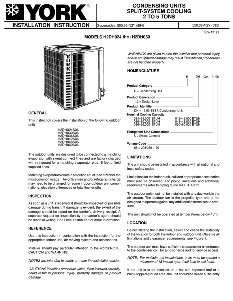
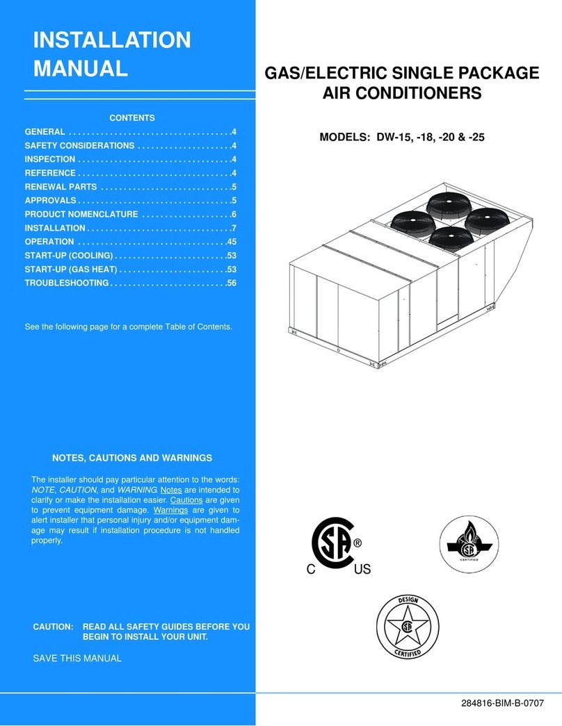
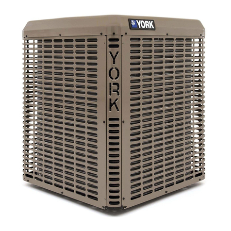
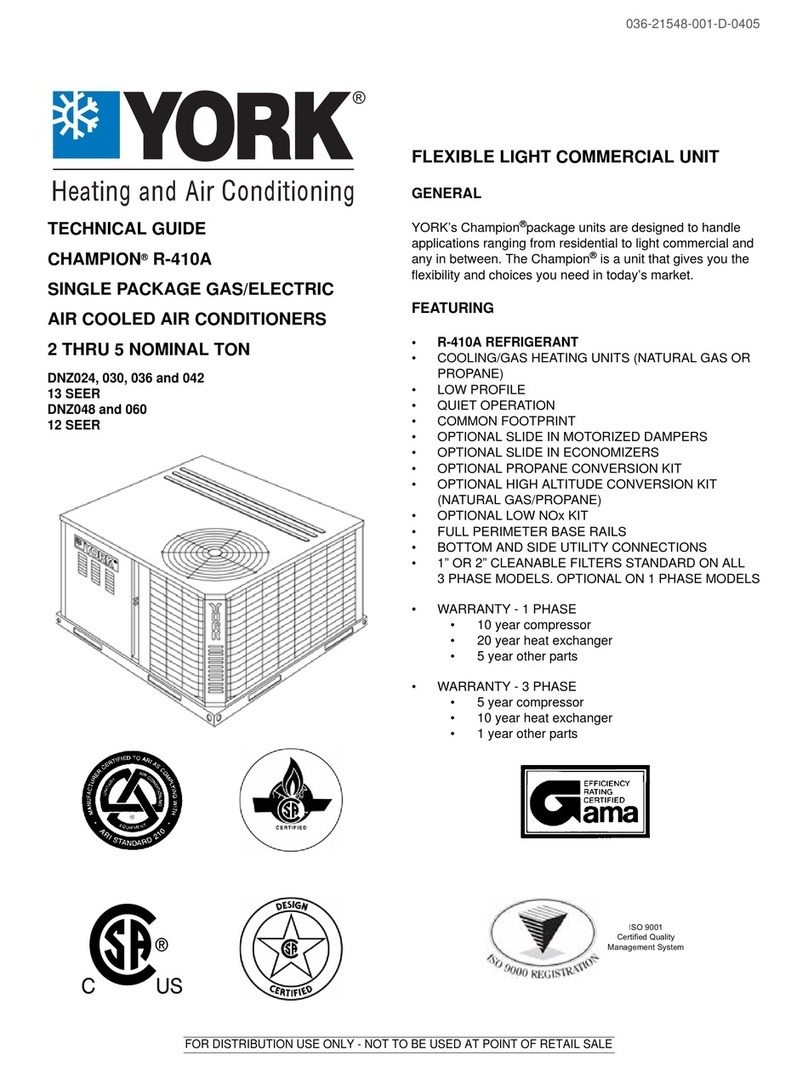
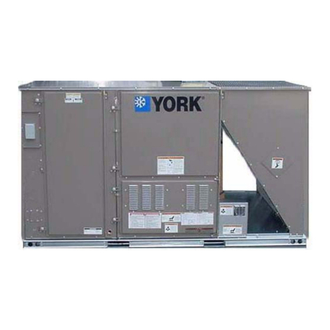
York ACTIVA 100 User manual

ACTIVA SERIES ROOF TOP Air
Conditioners 100/175
Installation manual
Ref.: N-40428_EN 0413

Index
1Installation manual...................................................................................................................1
1.1 Safety instructions....................................................................................................................2
1.2 Icons used in this document.....................................................................................................2
1.3 Instructions for storage, transport and handling of the unit......................................................3
1.3.1 Disposal of packaging..............................................................................................................3
1.3.2 Hoisting points..........................................................................................................................4
1.3.3 Centre of gravity.......................................................................................................................5
1.4 Technical data..........................................................................................................................6
1.4.1 ARC technical and physical data (Only cooling)......................................................................6
1.4.2 ARH technical and physical data (Heat pump).........................................................................7
1.4.3 Unit sound pressure data.........................................................................................................8
1.4.4 Weight options and accessories...............................................................................................8
1.5 ARC / ARH units with auxiliary heating element......................................................................9
1.6 Limits of use.............................................................................................................................9
1.7 Measurements, clearances and accesses.............................................................................10
1.7.1 Dimensions of the duct connections.......................................................................................10
1.7.2 Connections for supply and return ducts................................................................................12
1.7.3 General measurements and accesses...................................................................................13
1.8 ARC output.............................................................................................................................15
1.8.1 ARC - 100 cooling capacities.................................................................................................15
1.8.2 ARC - 125 cooling capacities.................................................................................................15
1.8.3 ARC - 150 cooling capacities.................................................................................................16
1.8.4 ARC - 175 cooling capacities.................................................................................................16
1.9 ARH output.............................................................................................................................17
1.9.1 ARH - 100 cooling capacities.................................................................................................17
1.9.2 ARH - 125 cooling capacities.................................................................................................17
1.9.3 ARH - 150 cooling capacities.................................................................................................18
1.9.4 ARH - 175 cooling capacities.................................................................................................18
1.9.5 ARH - 100 thermodynamic heating capacities.......................................................................19
1.9.6 ARH - 125 thermodynamic heating capacities.......................................................................19
1.9.7 ARH - 150 thermodynamic heating capacities.......................................................................20
1.9.8 ARH - 175 thermodynamic heating capacities.......................................................................20
1.10 Indoor fan...............................................................................................................................21
1.10.1 Features table........................................................................................................................21
1.10.2 Indoor fan output tables..........................................................................................................21
1.11 Pressure drop in options/accessories....................................................................................27
1.12 Instructions for installation and connection of the unit...........................................................27
1.12.1 Characteristics of the location................................................................................................27
1.12.2 Characteristics of the facility where the unit will be installed..................................................28
1.12.3 Specifications for the foundation or anchoring of the unit......................................................29
1.12.4 Characteristics of utility provider connections........................................................................29
1.12.5 Connection and preparation of the various connections........................................................29
Index
i

1.13 Instructions for starting up the unit.........................................................................................32
1.13.1 Electrical checks.....................................................................................................................32
1.14 Unblocking the unit safely in case of breakdown................................................................... 33
1.15 Regular maintenance tasks performed by specialised personnel..........................................33
1.15.1 Planned Maintenance Schedule.............................................................................................34
1.15.2 Maintenance tasks performed by specialised personnel........................................................34
2Options and accessories........................................................................................................37
2.1 DPC-1 Programmable digital thermostat with communication...............................................39
2.1.1 HVAC modes..........................................................................................................................39
2.1.2 Button functions......................................................................................................................42
2.2 Economiser, modulating, temperature control....................................................................... 43
2.3 Enthalpy probes..................................................................................................................... 44
2.4 Indoor air quality probe.......................................................................................................... 44
2.5 Barometric excess pressure damper..................................................................................... 44
2.6 Exhaust fan............................................................................................................................ 45
2.7 Fixed outdoor air damper.......................................................................................................46
2.8 Low temperature control (low ambient)..................................................................................46
2.9 Air filters F6 and F7................................................................................................................46
2.10 Dirty filter pressure switches.................................................................................................. 46
2.11 Smoke detector......................................................................................................................46
2.12 Fire detection thermostat....................................................................................................... 47
2.13 Hot water coil......................................................................................................................... 47
2.14 Heating element.....................................................................................................................47
2.15 Outdoor coil protection...........................................................................................................47
2.16 Anti-vibration kit......................................................................................................................47
2.17 Copper fin coils...................................................................................................................... 47
2.18 Roofcurb mounting base, fixed type.......................................................................................47
2.19 Roofcurb mounting base, adjustable type..............................................................................48
3Unit installation data...............................................................................................................50
3.1 List of tests for unit start-up....................................................................................................51
3.2 Start-up data.......................................................................................................................... 52
4Wiring diagrams..................................................................................................................... 54
4.1 Micro switch configuration......................................................................................................55
4.2 Fault table.............................................................................................................................. 56
4.3 Incidents.................................................................................................................................57
4.3.1 Test button............................................................................................................................. 58
4.4 DPC-1 thermostat.................................................................................................................. 58
4.5 ARC/ARH 100 – 125 wiring diagrams....................................................................................59
4.6 ARC/ARH 150 – 175 wiring diagrams....................................................................................62
Index
ii

1
Installation manual

1.1 Safety instructions
This document contains the necessary information for the safe and efficient transportation, assembly
and installation of the air conditioning unit. This guarantees the condition of the unit and its operating
safety.
Only an authorised company may assemble the air conditioning unit.
ATTENTION
Only authorised companies with the appropriate technical resources and suitably trained personnel may
install the air conditioning unit.
CAUTION
The specialists responsible for installing the air conditioning unit must make sure they have all of the
information and knowledge required to correctly install, test and deliver the unit. Johnson Controls Inc.
shall not be considered responsible for any damage caused by installation of the unit that is no consistent
with that described in this document or others specifically provided with the unit.
During regular equipment installation, the fitter must pay special attention to certain situations in order
to prevent injuries or damage to the unit.
Situations that could jeopardise the safety of the fitter or that of others nearby or that could put the unit
itself at risk are clearly indicated in this manual.
A series of special symbols are used to clearly identify these situations.
Pay careful attention to these symbols and to the messages following them, as your safety and the safety
of others depends on it.
1.2 Icons used in this document
DANGER
•The text following this symbol contains information and instructions relating directly to your safety
and physical well-being.
•Not taking these instructions into account could lead to serious, very serious or even fatal injuries to
you and others in the proximities of the unit.
Information can also be found on safe procedures during unit handling. This will help reduce the risk of
accidents.
CAUTION
•The text following this symbol contains information and instructions relating directly to your safety
and physical well-being.
•Not taking these instructions into account could lead to minor injuries to you and others in the
proximities of the unit.
•Not taking these instructions into account could lead to unit damage.
Information can also be found on safe procedures during unit handling. This will help reduce the risk of
accidents.
NOTE
•The text following this symbol contains information or instructions that may be of use or that is worthy
of a more thorough explanation.
•Instructions regarding inspections to be made on unit parts or systems may also be included.
1Installation manual
1.1 Safety instructions
2

1.3 Instructions for storage, transport and handling of the unit
Delivery inspection
The unit should be carefully inspected for visible damage or abnormalities as soon as it is received.
Any abnormalities or damage to the unit should be communicated to both the transportation and
insurance company in writing.
Storage instructions
The unit should be stored in a place suitable to the purpose (warehouse or similar), protected from the
weather, water, humidity and dust.
Cover the unit with a canvas of a suitable size.
The unit should be appropriately protected from knocks and dust, ensuring the protective parts it was
supplied with remain in place. Where these are not in place, establish the necessary protections and/or
barriers to keep vehicles or fork-lift trucks away.
Transport and handling of the unit
The units should only be handled by personnel from the company responsible for their installation.
Transport of the unit should be in such a manner that no damage is caused by faulty or inadequate
mooring to the bed or body of the vehicle.
Where necessary, protect all of the edges of the unit against knocks and scratches and moor it to the
bed or body of the vehicle using suitable textile belts or slings to keep it perfectly still.
ATTENTION
Do not use fork lifts in operations to load and unload the unit.
Loading and unloading the unit from a truck or trailer should be on flat, solid ground using a crane with
sufficient capacity.
1.3.1 Disposal of packaging
The packaging is recyclable. Dispose of it in the appropriate place or take it to an appropriate collection
centre. Respect the regulations in force for this type of waste in the country where the unit is being
installed.
Packaging remains must be correctly disposed of. Improper disposal of packaging generates
environmental problems that affect human life.
Installation manual 1
Instructions for storage, transport and handling of the unit 1.3
3

1.3.2 Hoisting points
The points designed for hoisting the unit are located
on the beams on its base -arrows-.
Install 5/8" shackles -A- on the points designed for
hoisting.
ATTENTION
Do not use fork lifts in operations to load and unload
the unit.
Before hoisting the unit, check that the cables or
slings are firmly hooked to these points and make
sure the crane and the cables or slings are capable of
lifting the weight.
See the weight in the technical data table or on the
rating plate.
Do not forget to include the weight of the options
installed in the unit.
Place spacers -1- at the top of the unit to prevent the
cables or slings from touching it.
Attach guide ropes so that the unit does not rotate
freely.
The cables or slings should be long enough to form
an angle of over 45° to the horizontal plane. Hoist the
unit keeping it in a horizontal position.
DANGER
There should not be onlookers within a radius of 10
m of the unit when it is being hoisted.
A
A
A
A
A
1
1Installation manual
1.3 Instructions for storage, transport and handling of the unit
4

1.3.3 Centre of gravity
Models A B
100 / 125 1185 1760
150 / 175 1160 2380
All measurements in mm.
1. End of the outdoor coils
2. Approximate centre of gravity
A
B
1
2
Installation manual 1
Instructions for storage, transport and handling of the unit 1.3
5

1.4 Technical data
1.4.1 ARC technical and physical data (Only cooling)
ARC/ARG models 100 125 150 175
Cooling capacity (1)
Net cooling capacity kW 108 122 149 169
Rated absorbed power kW 34 41 59 64
Net EER 3,46 3,21 3,13 2,91
Heating Optional heating element heating capacity (400 V) (2) kW 37 ‑ 50 37 ‑ 50 ‑ 60
Circuits No. 2 2
Compressors
Rated/start-up current A 4 x 13 / 111 4 x 15 / 118 4 x 20 / 140 4 x 24 / 198
Type and quantity (per circuit) Scroll x 2 (1 Tándem)
Degree of protection IP21
Coolant
(R-410A) Charge (per circuit) kg 20 20 25 25,5
Power supply V/ph/Hz 400 / 3 / 50
Indoor fan (3)
Rated air flow m3/h 19000 21000 27000 30000
Rated static pressure / maximum with rated flow Pa
Maximum flow rate m3/h 22000 25000 32000 35000
Minimum flow rate m3/h 16000 18000 22000 25000
Motor (IP55) Maximum power / Quantity kW 5,5 / 1 4 / 2
Maximum current A 12,5 12,5 9,5 x 2 9,5 x 2
Indoor coil (evaporator)
Number of elements No. 4
Distance between fins mm 1,81 1,81
Front surface m23,5 5,2
Air filters (G4)
Quantity per unit No. 6
Dimensions mm 823 x 730 x 48 823 x 880 x 48
Outdoor fan
(Data per circuit)
Diameter/number mm 800 / 1 800 / 2
Total rated flow m3/h 18000 36000
Motor (IP54) kW 1,9 1,9 (x 2)
Rated current A 3,3 3,3 (x 2)
Outdoor coil (condenser)
(Data per circuit)
Number of elements No. 3 (x 2) 3 (x 2)
Distance between fins mm 2,11 2,11
Front area m21,86 (x 2) 2,62 (x 2)
Net dimensions (4)
Height mm 1862 + 280 ventilador
Length mm 4036 5085
Width mm 2250 2250
Net weight (basic unit without
accessories) (4) kg
Electrical features of the unit
Total rated power kW 34 41 59 64
Total rated current A 65 75 110 125
Total maximum power kW 49 57 74 85
Total maximum current A 88 101 137 157
Circuit breaker (K Curve) (5) A 100 125 160 200
Minimum cable section (6) mm23 x 35 3 x 50 3 x 50 3 x 70
(1) Data in compliance with Eurovent conditions, summer: indoor 27 °C TS/19 °C TH ‑ outdoor TS 35 °C. Winter: Indoor TS 20 °C, outdoor TS 7 °C / TH 6 °C (TS Dry-bulb thermometer; TH Wet-
bulb thermometer), with vertical ducts, rated air flow and pressure.
Net EER = Net cooling capacity / Total absorbed power (according to Eurovent).
(2) Add the inside motor consumption to find the total calorific capacity.
(3) See
Indoor fan, see on page 21
.
(4) Consider the additional weight of options and accessories. To do so, see
Weight options and accessories, see on page 8
.
(5) and
(6)
Circuit breaker with K curve, according to DIN, VDE 0660-104. Section of cables for the power supply line based on copper conductors, 105 °C. The circuit breaker and the section of power
supply cables indicated are for guidance. They should be adjusted based on the requirements of each installation, distance between units, fall in planned voltage and on the application of the
current regulations with respect to the country where the unit is being installed.
1 Installation manual
1.4 Technical data
6

1.4.2 ARH technical and physical data (Heat pump)
ARH/ARD models 100 125 150 175
Cooling capacity (1)
Net cooling capacity kW 108 122 149 169
Rated absorbed power kW 34 41 59 64
Net EER 3,46 3,21 3,13 2,91
Heat capacity (1)
Net heating capacity kW 105 118 147 167
Rated absorbed power kW 33 37 53 61
Net COP 3,48 3,44 3,20 2,96
Optional heating element heating capacity
(400 V) (ARH) (2) kW 37 ‑ 50 37 ‑ 50 ‑ 60
Circuits No. 2
Compressors
Rated/start-up current A 4 x 13 / 111 4 x 15 / 118 4 x 20 / 140 4 x 24 / 198
Type and quantity (per circuit) Scroll x 2 (1 Tándem)
Degree of protection IP21
Coolant
(R-410A) Charge (per circuit) kg 20 20 25,5 26
Power supply V/ph/Hz 400 / 3 / 50
Indoor fan (3)
Rated air flow m3/h 19000 21000 27000 30000
Rated static pressure / maximum with rated
flow Pa
Maximum flow
rate m3/h 22000 25000 32000 35000
Minimum flow
rate m3/h 16000 18000 22000 25000
Motor (IP55) Maximum power
/ quantity kW 5,5 / 1 4 / 2
Maximum current A
Indoor coil (evaporator)
Number of elements No. 4
Distance between fins mm 1,81 1,81
Front surface m23,5 5,2
Air filters (G4)
Quantity per unit No. 6
Dimensions mm 823 x 730 x 48 823 x 880 x 48
Outdoor fan
(data per circuit)
Diameter/number mm 800 / 1 800 / 2
Total rated flow m3/h 18000 36000
Motor (IP54) kW 1,9 1,9 (x 2)
Rated current A 3,3 3,3 (x 2)
Outdoor coil (condenser)
(data per circuit)
Number of elements No. 3 (x 2) 3 (x 2)
Distance between fins mm 2,11 2,11
Front area m21,86 (x 2) 2,62 (x 2)
Net dimensions (4)
Height mm 1862 + 280 ventilador
Length mm 4036 5085
Width mm 2250 2250
Net weight (basic unit without acces‐
sories) (4) kg
Electrical features of the unit
Total rated power kW 34 41 59 64
Total rated current A 65 75 110 125
Total maximum power kW 49 57 74 85
Total maximum current A 88 101 137 157
Circuit breaker (K Curve) (5) A 100 125 160 200
Minimum cable section (6) mm23 x 35 3 x 50 3 x 50 3 x 70
(1) Data in compliance with Eurovent conditions, summer: indoor 27 °C TS/19 °C TH ‑ outdoor TS 35 °C. Winter: Indoor TS 20 °C, outdoor TS 7 °C / TH 6 °C (TS Dry-bulb thermometer; TH Wet-
bulb thermometer), with vertical ducts, rated air flow and pressure.
Net EER = Net cooling capacity / Total absorbed power (according to Eurovent).
Net COP = Net heating capacity / Total absorbed power (according to Eurovent).
(2) Add the inside motor consumption to find the total calorific capacity.
(3) See
Indoor fan, see on page 21
(4) Consider the additional weight of options and accessories. To do so, see
Weight options and accessories, see on page 8
.
(5) and
(6)
Circuit breaker with K curve, according to DIN, VDE 0660-104. Section of cables for the power supply line based on copper conductors, 105 °C. The circuit breaker and the section of power
supply cables indicated are for guidance. They should be adjusted based on the requirements of each installation, distance between units, fall in planned voltage and on the application of the
current regulations with respect to the country where the unit is being installed.
Installation manual 1
Technical data 1.4
7
1.4.3 Unit sound pressure data
Octave band sound spectrum dB(A), outdoor
Models 100 125 150 175
125 Hz 87,3 90,1
250 Hz 85,4 86,6
500 Hz 84,5 84,2
1000 Hz 84,9 84
2000 Hz 79,7 79
4000 Hz 73,4 75,5
8000 Hz 68,4 73,2
Sound power level dB (A) 88,4 88,5
Sound pressure level at 5 m dB (A) 63,7 63,8
Sound pressure level at 10 m dB (A) 57,6 57,7
Octave band sound spectrum dB(A), indoor
Models 100 125 150 175
125 Hz 89,8 94,4
250 Hz 77,5 83,2
500 Hz 75,7 76,9
1000 Hz 75,6 76,4
2000 Hz 75 75,7
4000 Hz 73,8 76,4
8000 Hz 70,3 74,5
Sound power level dB (A) 83,3 84,2
1.4.4 Weight options and accessories
Models 100 125 150 175
Economiser kg 88 88 100 100
Exhaust fan (axial) kg 75 75 106 106
Roofcurb mounting base (fixed/adjustable) kg 152 / 248 186 / 302
Heating element kg
Hot water coil kg
Fixed outdoor air intake kg 39 39 43 43
Barometric damper kg 28 28 36 36
Copper fin coil indoor 105 160
outdoor 144 204
Side air supply 11 13
1 Installation manual
1.4 Technical data
8

1.5 ARC / ARH units with auxiliary heating element
The power supply to the heating resistor must be independent to the general power supply to the unit
and must be fitted with its own circuit breaker according to the table:
ARC Model
Power
supply
V/Ph/Hz
Heating element
Maximum circuit breaker
(K Curve) (1)
Minimum cable cross-section
(mm2) (2)
Power
(kW) Stages (No.) Current
(A)
100 400/3/50
37 2 54 63 16
50 2 72 80 25
125 400/3/50
37 2 54 63 16
50 2 72 80 25
150 400/3/50
37 2 54 63 16
50 2 72 80 25
60 2 87 100 35
175 400/3/50
37 2 54 63 16
50 2 72 80 25
60 2 87 100 35
(1) K Curve (DIN, VDE 0660-104).
(2) Based on copper conductors 105 °C.
1.6 Limits of use
Model 100 125 150 175
Voltage limits Min./Max V 342/457
ARC
Temperature of air inlet in indoor coil
WB °C Min./Max. 15/23 15/23 15/23 15/23
DB °C Min/Max 20/32 20/32 20/32 20/32
Outdoor temperature (without condensa‐
tion control) TS °C Min. 10 10 7 7
Maximum outdoor tempera‐
ture (1)
At full
load TS °C 46 46 46 46
At partial
load TS °C 52 52 52 52
ARH
Summer
cycle
Temperature of air inlet in indoor coil
WB °C Min./Max. 15/23 15/23 15/23 14/23
DB °C Min/Max 20/32 20/32 20/32 20/32
Outdoor temperature (without condensa‐
tion control) TS °C Min. 10 10 7 7
Maximum outdoor tempera‐
ture (1)
At full
load TS °C 46 46 46 46
At partial
load TS °C 52 52 52 52
Winter
cycle
Temperature of air inlet in indoor coil DB °C Min/Max 10/25 10/25 10/25 10/25
Outdoor temperature DB °C Min/Max -10/20 -10/20 -10/20 -10/20
1. Direct sunlight on the unit should be prevented when temperatures are higher than 43 °C. If placed under some kind of protective cover, the cover should not interfere
with the flow of outdoor ventilation.
2. The gas heating units (ARG/ARD) are only appropriate for use with gas. In LPG (Liquefied Petroleum Gas, propane) installations, it must be ensured that in no case
should gasoline in liquid form reach the gas group.
DB: Dry-bulb Thermometer; TH: Wet-bulb thermometer.
Installation manual 1
ARC / ARH units with auxiliary heating element 1.5
9

1.7 Measurements, clearances and accesses
1.7.1 Dimensions of the duct connections
Models 100 / 175, side ducts (horizontal)
NOTE
Floor plan without the top panel
S1 Lateral supply
R1 Lateral return
Model
ARC /
ARH
A B C D L1 H1 L2 H2
100 / 125 135 365 212 192 1380 575 1720 570
150 / 175 135 390 212 192 1830 645 2170 570
1 Installation manual
1.7 Measurements, clearances and accesses
10

Models 100 / 175, lower ducts (vertical)
L4 G
J
H4
H3
F
L3 E
S2
R2
NOTE
Floor plan without the top panel
S2 Bottom supply
R2 Lower return
Model
ARC /
ARH
E F G J L3 H3 L4 H4
100 / 125 145 135 163 125 1465 750 1755 510
150 / 175 368 135 163 120 1690 750 2205 400
Installation manual 1
Measurements, clearances and accesses 1.7
11

1.7.2 Connections for supply and return ducts
Units are shipped with the openings for the connection of the return duct covered.
For applications with downward discharge ducts
1. The return compartment is accessed by removing
the access panel -B2-.
NOTE
For the supply duct -S1-, it is not necessary to
remove any cover or access panel.
2. Remove and dispose of the lower cover of the duct
-R2- (return). In order to do this, loosen the three
bolts -D- that fix the cover to the base.
3. After removing the lower cover, reattach the side
panel, ensuring that the seal is hermetic.
For applications with sideways discharge ducts
NOTE
For the supply duct -S2-, it is not necessary to remove
any cover or access panel.
1. Access the return compartment via the access
panel -B2- and loosen the bolts -E- from the inside.
2. Remove and dispose of the side cover -A2-.
3. After removing the side cover, reattach the side
panel, ensuring that the seal is hermetic.
R2
B2
D
A2
B2
E
E
1Installation manual
1.7 Measurements, clearances and accesses
12

1.7.3 General measurements and accesses
Minimum clearance above the unit
The unit is designed to be installed outdoors.
In ground level installations, the building eaves must not be at a vertical distance of less than 3000 mm
from the top of the unit.
Installation manual 1
Measurements, clearances and accesses 1.7
13

Models ARC/ARH ‑ 100 / 175
A5
C3
2000
4
C2
1500
2000
D
A1
A4 A3
132
A1
A2
C1
A5
5
100/125 : x 2
150/175 : x 4
3000
Model A B C D
100 / 125 4036 1957 1123 2300
150 / 175 5085 2557 1473 2750
A1. Access to indoor fan
A2. Access to electrical box
A3. Access to return/economiser/filters
A4. Access to heating/supply options
A5. Access to cooling circuit
C1. Supply side cover
C2. Return side cover / air exhaust options
C3. Outdoor air inlet cover, optional
1. Drain connection ∅ 41 x 35 Long
2. Main switch
3. Side inlet for power (PG48) and control (PG21) cables
4. Instructions for minimum free space around the unit
5. Inlet in the base for power (PG48) and control (PG21) cables
1 Installation manual
1.7 Measurements, clearances and accesses
14

1.8 ARC output
1.8.1 ARC ‑ 100 cooling capacities
Return air Outdoor coil air temperature (TS)
Flow rate
m3/h
WB
°C
27 °C 35 °C 46 °C
PT
kW
PC
kW
Sensible power kW
PT
kW
PC
kW
Sensible power kW
PT
kW
PC
kW
Sensible power kW
TS inlet temp. in indoor coil TS inlet temp. in indoor coil TS inlet temp. in indoor coil
22 24 27 30 22 24 27 30 22 24 27 30
(Mini‐
mum)
16000
23 122 25,4 — 42 58 74 116 27,8 — 40 56 72 105 30,7 — 36 52 68
19 111 24,6 55 66 82 98 105 26,7 53 63 79 95 94 28,8 49 60 75 91
17 105 24 70 76 93 105 96 26,4 65 74 89 96 86 28,6 59 69 85 86
15 94 23,8 76 86 94 94 90 25,9 74 84 90 90 81 28,3 70 81 81 81
(Nominal)
19000
23 126 25,7 — 44 62 81 119 28,2 — 41 60 79 108 31,2 — 38 56 75
19 114 24,9 59 71 90 108 108 27,1 56 69 87 106 97 29,3 52 65 83 97
17 108 24,4 77 85 103 108 99 26,8 71 81 99 99 89 29 64 77 89 89
15 97 24,1 83 95 97 97 93 26,3 81 93 93 93 83 28,7 77 83 83 83
(Maxi‐
mum)
22000
23 129 26,1 — 49 66 87 123 28,6 — 42 64 85 111 31,6 — 39 60 82
19 117 25,3 62 76 97 117 111 27,5 59 74 99 111 99 29,7 56 70 91 91
17 110 24,8 84 92 110 110 102 27,2 77 88 102 102 91 29,4 69 83 91 91
15 99 24,5 90 99 99 99 95 26,7 88 95 95 95 85 29,2 84 85 85 85
* Data in accordance with Eurovent Rooftop program certification conditions
PT: Total Power; PC: Power absorbed by the compressor
WB: Wet-bulb temperature; TS: Dry bulb temperature.
1.8.2 ARC ‑ 125 cooling capacities
Return air Outdoor coil air temperature (TS)
Flow rate
m3/h
WB
°C
27 °C 35 °C 46 °C
PT
kW
PC
kW
Sensible power kW
PT
kW
PC
kW
Sensible power kW
PT
kW
PC
kW
Sensible power kW
TS inlet temp. in indoor coil TS inlet temp. in indoor coil TS inlet temp. in indoor coil
22 24 27 30 22 24 27 30 22 24 27 30
(Mini‐
mum)
18000
23 138 30,8 — 48 66 83 131 33,7 — 45 63 81 118 37,3 — 41 59 76
19 126 29,8 63 74 92 110 118 32,4 60 71 89 107 107 35 55 67 85 102
17 118 29,2 80 87 105 118 109 32,1 73 83 100 109 97 34,7 66 78 96 97
15 107 28,8 85 97 107 107 102 31,4 83 94 102 102 91 34,3 78 90 91 91
(Nominal)
21000
23 143 31,2 — 49 70 90 135 34,1 — 47 67 88 122 37,7 — 43 63 83
19 129 30,2 66 80 100 120 122 32,8 63 77 97 117 110 35,4 59 72 93 110
17 122 29,5 87 94 115 122 112 32,5 79 90 110 112 100 35,1 72 85 100 100
15 110 29,2 93 106 110 110 105 31,8 90 103 105 105 94 34,8 86 94 94 94
(Maxi‐
mum)
25000
23 146 31,6 — 51 75 99 138 34,6 — 48 72 96 125 38,3 — 44 68 92
19 133 30,6 70 86 110 133 125 33,3 67 83 107 125 113 36 63 79 103 103
17 125 30 97 103 125 125 115 33 87 99 115 115 103 35,6 78 94 103 103
15 113 29,6 102 113 113 113 108 32,3 99 108 108 108 96 35,3 94 96 96 96
* Data in accordance with Eurovent Rooftop program certification conditions
PT: Total Power; PC: Power absorbed by the compressor
WB: Wet-bulb temperature; TS: Dry bulb temperature.
Installation manual 1
ARC output 1.8
15

1.8.3 ARC ‑ 150 cooling capacities
Return air Outdoor coil air temperature (TS)
Flow rate
m3/h
WB
°C
27 °C 35 °C 46 °C
PT
kW
PC
kW
Sensible power kW
PT
kW
PC
kW
Sensible power kW
PT
kW
PC
kW
Sensible power kW
TS inlet temp. in indoor coil TS inlet temp. in indoor coil TS inlet temp. in indoor coil
22 24 27 30 22 24 27 30 22 24 27 30
(Mini‐
mum)
22000
23 168 35,2 — 58 80 101 159 38,6 — 55 77 98 143 42,7 — 50 72 93
19 152 34,1 76 91 112 134 143 37,1 73 87 109 131 129 40,1 67 82 104 125
17 143 33,4 95 106 128 143 132 36,7 88 101 123 132 117 39,7 81 95 117 117
15 129 33 104 118 129 129 123 36 101 116 123 123 110 39,3 96 110 110 110
(Nominal)
27000
23 174 35,9 — 60 87 113 165 39,3 — 57 84 110 149 43,5 — 52 79 105
19 158 34,8 82 99 126 152 149 37,8 78 96 122 149 134 40,8 73 91 117 134
17 149 34 107 118 145 149 137 37,4 99 113 137 137 122 40,4 90 107 122 122
15 134 33,6 116 134 134 134 128 36,7 113 128 128 128 115 40,1 108 115 115 115
(Maxi‐
mum)
32000
23 178 36,4 — 62 93 124 169 39,8 — 59 90 121 152 44 — 54 85 116
19 162 35,2 87 107 138 162 153 38,3 83 104 135 153 137 41,4 78 99 130 137
17 153 34,5 119 130 153 153 140 37,9 108 124 140 140 125 41 98 119 125 125
15 137 34,1 128 137 137 137 131 37,2 124 131 131 131 117 40,6 117 117 117 117
* Data in accordance with Eurovent Rooftop program certification conditions
PT: Total Power; PC: Power absorbed by the compressor
WB: Wet-bulb temperature; TS: Dry bulb temperature.
1.8.4 ARC ‑ 175 cooling capacities
Return air Outdoor coil air temperature (TS)
Flow rate
m3/h
WB
°C
27 °C 35 °C 46 °C
PT
kW
PC
kW
Sensible power kW
PT
kW
PC
kW
Sensible power kW
PT
kW
PC
kW
Sensible power kW
TS inlet temp. in indoor coil TS inlet temp. in indoor coil TS inlet temp. in indoor coil
22 24 27 30 22 24 27 30 22 24 27 30
(Mini‐
mum)
25000
23 191 43,3 — 66 90 115 181 47,4 — 62 87 112 163 52,4 — 57 81 106
19 173 42 86 103 127 152 163 45,6 83 99 123 148 147 49,2 76 93 117 142
17 163 41 109 121 145 163 150 45,1 101 115 139 150 134 48,8 92 108 132 134
15 147 40,6 118 134 147 147 140 44,2 115 131 140 140 126 48,3 108 124 126 126
(Nominal)
30000
23 198 44,1 — 68 97 127 187 48,3 — 65 94 123 169 53,4 — 59 88 118
19 179 42,7 92 112 141 170 169 46,4 88 108 137 166 152 50,1 82 102 131 152
17 169 41,8 122 133 162 169 155 45,9 111 127 155 155 139 49,6 101 120 139 139
15 152 41,3 130 150 152 152 145 45 127 145 145 145 130 49,2 120 130 130 130
(Maxi‐
mum)
35000
23 202 44,7 — 70 104 138 192 48,9 — 67 101 134 173 54,1 — 61 95 129
19 183 43,2 97 120 154 183 173 47 93 116 150 173 156 50,8 87 110 144 156
17 173 42,3 134 144 173 173 159 46,5 121 138 159 159 142 50,3 109 131 142 142
15 156 41,8 142 156 156 156 148 45,6 138 148 148 148 133 49,8 132 133 133 133
* Data in accordance with Eurovent Rooftop program certification conditions
PT: Total Power; PC: Power absorbed by the compressor
WB: Wet-bulb temperature; TS: Dry bulb temperature.
1 Installation manual
1.8 ARC output
16

1.9 ARH output
1.9.1 ARH ‑ 100 cooling capacities
Return air Outdoor coil air temperature (TS)
Flow rate
m3/h
WB
°C
27 °C 35 °C 46 °C
PT
kW
PC
kW
Sensible power kW
PT
kW
PC
kW
Sensible power kW
PT
kW
PC
kW
Sensible power kW
TS inlet temp. in indoor coil TS inlet temp. in indoor coil TS inlet temp. in indoor coil
22 24 27 30 22 24 27 30 22 24 27 30
(Mini‐
mum)
16000
23 122 25,4 — 42 58 74 116 27,8 — 40 56 72 105 30,7 — 36 52 68
19 111 24,6 55 66 82 98 105 26,7 53 63 79 95 94 28,8 49 60 75 91
17 105 24 70 76 93 105 96 26,4 65 74 89 96 86 28,6 59 69 85 86
15 94 23,8 76 86 94 94 90 25,9 74 84 90 90 81 28,3 70 81 81 81
(Nominal)
19000
23 126 25,7 — 44 62 81 119 28,2 — 41 60 79 108 31,2 — 38 56 75
19 114 24,9 59 71 90 108 108 27,1 56 69 87 106 97 29,3 52 65 83 97
17 108 24,4 77 85 103 108 99 26,8 71 81 99 99 89 29 64 77 89 89
15 97 24,1 83 95 97 97 93 26,3 81 93 93 93 83 28,7 77 83 83 83
(Maxi‐
mum)
22000
23 129 26,1 — 49 66 87 123 28,6 — 42 64 85 111 31,6 — 39 60 82
19 117 25,3 62 76 97 117 111 27,5 59 74 99 111 99 29,7 56 70 91 91
17 110 24,8 84 92 110 110 102 27,2 77 88 102 102 91 29,4 69 83 91 91
15 99 24,5 90 99 99 99 95 26,7 88 95 95 95 85 29,2 84 85 85 85
* Data in accordance with Eurovent Rooftop program certification conditions
PT: Total Power; PC: Power absorbed by the compressor
WB: Wet-bulb temperature; TS: Dry bulb temperature.
1.9.2 ARH ‑ 125 cooling capacities
Return air Outdoor coil air temperature (TS)
Flow rate
m3/h
WB
°C
27 °C 35 °C 46 °C
PT
kW
PC
kW
Sensible power kW
PT
kW
PC
kW
Sensible power kW
PT
kW
PC
kW
Sensible power kW
TS inlet temp. in indoor coil TS inlet temp. in indoor coil TS inlet temp. in indoor coil
22 24 27 30 22 24 27 30 22 24 27 30
(Mini‐
mum)
18000
23 138 30,8 — 48 66 83 131 33,7 — 45 63 81 118 37,3 — 41 59 76
19 126 29,8 63 74 92 110 118 32,4 60 71 89 107 107 35 55 67 85 102
17 118 29,2 80 87 105 118 109 32,1 73 83 100 109 97 34,7 66 78 96 97
15 107 28,8 85 97 107 107 102 31,4 83 94 102 102 91 34,3 78 90 91 91
(Nominal)
21000
23 143 31,2 — 49 70 90 135 34,1 — 47 67 88 122 37,7 — 43 63 83
19 129 30,2 66 80 100 120 122 32,8 63 77 97 117 110 35,4 59 72 93 110
17 122 29,5 87 94 115 122 112 32,5 79 90 110 112 100 35,1 72 85 100 100
15 110 29,2 93 106 110 110 105 31,8 90 103 105 105 94 34,8 86 94 94 94
(Maxi‐
mum)
25000
23 146 31,6 — 51 75 99 138 34,6 — 48 72 96 125 38,3 — 44 68 92
19 133 30,6 70 86 110 133 125 33,3 67 83 107 125 113 36 63 79 103 103
17 125 30 97 103 125 125 115 33 87 99 115 115 103 35,6 78 94 103 103
15 113 29,6 102 113 113 113 108 32,3 99 108 108 108 96 35,3 94 96 96 96
* Data in accordance with Eurovent Rooftop program certification conditions
PT: Total Power; PC: Power absorbed by the compressor
WB: Wet-bulb temperature; TS: Dry bulb temperature.
Installation manual 1
ARH output 1.9
17
This manual suits for next models
1
Table of contents
Other York Air Conditioner manuals

York
York HA300 Quick start guide

York
York YHKMXH009BARX-FX User manual

York
York DNZ 060 User manual

York
York YCD18 THRU 60 Quick start guide

York
York J Series User manual

York
York HIDS006B21S User manual

York
York D2EB030 Quick start guide

York
York R-410A User manual

York
York D1EB036 User manual

York
York EHK-08G User manual

York
York SUNLINE PLUS D2EG 048 User manual

York
York 13 SEER CMB SERIES Guide

York
York ZJ037-061 User manual

York
York H4TS024 Quick start guide

York
York ZKT06 User manual

York
York HLCA-HLHA 07-36 Operating instructions

York
York GCGA36 THRU 76 Quick start guide

York
York H4TS024 User manual

York
York SUNLINE DHG 180 User manual

York
York ZS Series User manual