035-14511-001 Rev. A (0602)
10 Unitary Products Group
ENERGIZE CRANKCASE HEATER
This unit is equipped with a crankcase heater for the com-
pressor.
A warning label with an adhesive back is supplied in the unit
installation instruction packet. This label should be attached
to the field supplied disconnect switch where it will be easily
seen.
IMPORTANT - An attempt to start the compressor without
at least 8 hours of crankcase heat will damage the compres-
sor.
In order to energize the crankcase heater, set indoor two
stage cooling thermostat to "OFF" position. Close the line
power disconnect to the unit.
SYSTEM OPERATION
FIRST STAGE COOLING
With a call for first stage cooling, the compressor operates
one cylinder. The run winding (R) is connected through con-
tactor A to the capacitor and the start winding (S) is con-
nected to line voltage. The system operates at low discharge
pressure and high suction pressure.
SECOND STAGE OF COOLING
With a call for second stage cooling, the TS control will shut
the compressor off for two seconds then energize relays R1
and R2 on the TS control board. This will de-energize (open)
contactor A and energize (close) contactor B, connecting the
compressor run winding (R) to line voltage and the start wind-
ing (S) to the capacitor. The compressor runs in the reverse
direction with two cylinders compared to the first stage. The
system will operate with two cylinders until both first and sec-
ond stage are satisfied. The Y2OUT signal from the TS con-
trol causes the indoor blower to function at high speed.
If the room thermostat calls for second stage cooling (Y2) on
two consecutive cooling cycles, the next call for cooling for
either first or second stage will energize the unit in second
stage mode. The above mode will be reset to permit start up
on the first stage with only a Y1 call when the second stage
operation cycle runs less than 15 minutes or when 24V to the
TS control board is disconnected.
NOTE: The TS control must have a Y1 and a Y2 call to run
in second stage. A Y2 call without a Y1 call will not cause the
system to operate.
DEHUMIDIFICATION
The product is designed to run longer on first stage than a
regular single speed compressor system. This additional run
time provides for better dehumidification and consistent room
temperatures. However, there may be installation environ-
ments in which the humidity levels are unacceptable. In this
case the addition of a humidity control will resolve these
issues.
A humidistat installed with a variable speed air handler or fur-
nace reduces the airflow of the blower by 15% of the pro-
grammed speed during the dehumidification mode. This
lower airflow reduces the evaporator temperature increasing
the latent capacity. The humidistat for these variable speed
systems opens the humidistat contacts on humidity rise.
They are wired to the control system per Figure 7.
A dehumidistat installed with a single speed or 2-speed air
handler or furnace will force the system into second stage
mode to increase the latent capacity. It is critical that the low
speed blower operation is set as close to the recommended
airflow as possible to limit the number of times the unit will
run second stage for dehumidification purposes. The dehumi-
distats for these systems close the dehumidistat contacts on
humidity rise. They are wired to the control system per Fig-
ures 8 through 10.
ANTI-SHORT CYCLE TIMER
The control has a five minute time delay to prevent the sys-
tem from short cycling after a thermostat off cycle or power
interrupt. This five minute delay is initiated following the com-
pletion of a first stage cooling call (Y1) or the 24v power up of
the control. During this mode the control will not respond to
any thermostat inputs and the LED will flash a code 1 at the
control board.
For servicing or during installation of the condensing unit, the
time delay may be bypassed by momentarily jumping the two
test pins when there is a call for cooling (Y1 or Y2).
PRESSURE SWITCH OPERATION
The condensing unit is provided with high and low pressure
switches installed and wired into the control to provide addi-
tional protection for the system if any abnormal operating
conditions occur. The high pressure switch is threaded on a
Schrader fitting located in the liquid line of the outdoor unit
and a low pressure switch is brazed in the suction line of the
outdoor unit. These two controls are wired in series to the unit
control.
If the pressure switches detect a fault condition, they will
open (high pressure opens with pressures greater than 400
psi and low pressure opens with pressures less than 25 psi)
and the control will immediately shut down the unit. The con-
trol will go into a five-minute anti-short cycle mode inhibiting
any thermostat inputs. Following the anti-short cycle mode,
the control will permit the unit to start normally with the next
call for cooling as long as the pressure switches have reset
(high pressure resets at 300 ± 15 psi, low pressure resets at
65 ± 7 psi).
If the control detects a second pressure switch fault within
one hour of compressor run time, the unit will again shut
down and the unit control will lock out the unit until the fault
condition is reset. During this period, a code “2” will be
flashed at the control and provide a 24v signal on the X/L line.
HeartBeat – LED flash rate of 500 ms ON and 500 ms OFF
Flash/Error Code – LED flash rate of 350 ms ON and 350 ms
OFF for the number of codes and with a pause of 1.5 sec-
onds between flash codes.
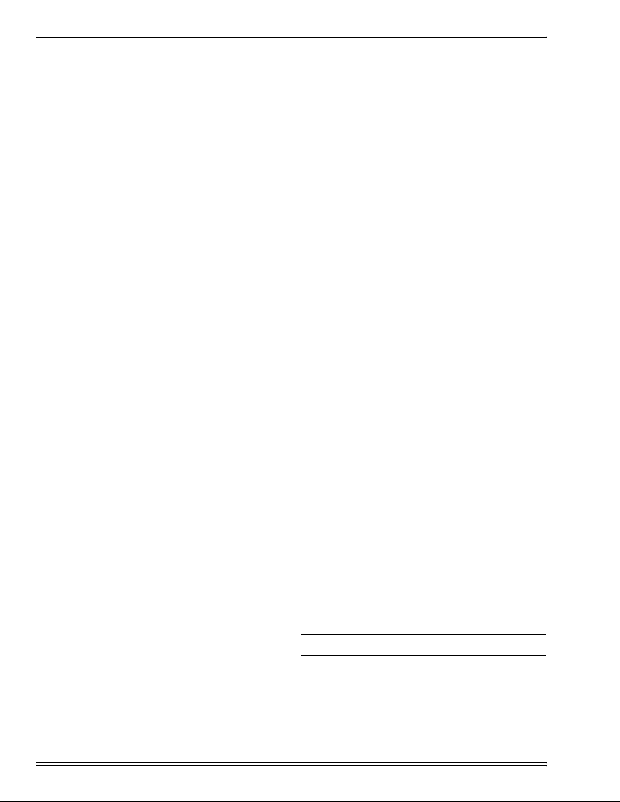
Table 3: FAULT CODES
TS Control
LED Description 24V @
X/L line
HeartBeat Normal Operation None
1 Flash Compressor waiting to complete
Anti-short cycle period None
2 Flash Compressor lockout out on safety
chain trip Yes
On Steady Control Failure Yes
Off No power or Control Failure


024-060BBA(D)(Q)-A(B)FX User manual")


 null")