manuals.online logo
Brands
  1. Home
  2. •
  3. Brands
  4. •
  5. York
  6. •
  7. Heat Pump
  8. •
  9. York HD Series User manual

York HD Series User manual

258919-UIM-B-0107
HD SERIES HORIZONTAL DUCT COILS FOR
COOLING/HEAT PUMPS
Field Installed TXV - Fle Coils
HD**S3XH1
Factory Installed R-22 TXV - Coils
HD**S2AH1 & HD**S2CH1
ISO 9001
Certified Quality
Management System
INSTALLATION MANUAL
INSTALLATION MANUALINSTALLATION MANUAL
INSTALLATION MANUAL
SECTION I: SAFETY
SECTION I: SAFETYSECTION I: SAFETY
SECTION I: SAFETY
This is a safety alert symbol. When you see this symbol on
labels or in manuals be alert to the potential for personal
injury.
Understand and pay particular attention to the signal words DANGER
WARNING or CAUTION.
DANGER indicates an imminently hazardous situation which if not
avoided will result in death or serious injury.
WARNING indicates a potentially hazardous situation which if not
avoided could result in death or serious injury.
CAUTION indicated a potentially hazardous situation which if not
avoided may result in minor or moderate injury. It is also used to alert
against unsafe practices and hazards involving only property damage.
SECTION II: GENERAL INFORMATION
SECTION II: GENERAL INFORMATIONSECTION II: GENERAL INFORMATION
SECTION II: GENERAL INFORMATION
This instruction covers the installation of the following coils with 80+ or
90+ AFUE furnaces or MA/MV air moving systems.
The coils have sweat connect fittings. All coils are shipped with a low
psi nitrogen holding charge.
Improper installation may create a condition where the operation of
the product could cause personal injury or property damage.
Improper installation, adjustment, alteration, service or mainte-
nance can cause injury or property damage. Refer to this manual
for assistance or additional information, consult a qualified installer
or service agency.
This product must be installed in strict compliance with the
enclosed installation instructions and any applicable local, state,
and national codes including, but not limited to building, electrical,
and mechanical codes.
The furnace area must not be used as a broom closet or for any
other storage purposes, as a fire hazard may be created. ever
store items such as the following on, near or in contact with the fur-
nace.
1. Spray or aerosol cans rags brooms dust mops vacuum
cleaners or other cleaning tools.
2. Soap powders bleaches waxes or other Cleaning com-
pounds; plastic items or containers; gasoline kerosene ciga-
rette lighter fluid dry cleaning fluids or other volatile fluid.
3. Paint thinners and other painting compounds.
4. Paper bags boxes or other paper products
ever operate the furnace with the blower door removed. To do so
could result in serious personal injury and/or equipment damage.
FIGURE 1: Component Location - HD Coil
COIL
TXV - BULB
TXV
LIST OF SECTIONS
SAFETY 1
GENERAL INFORMATION 1
COIL METERING DEVICES 2
DUCT CONNECTIONS 3
CONDENSATE DRAIN CONNECTIONS 3
REFRIGERANT LINE CONNECTION 4
COIL CLEANING 4
AIR SYSTEM ADJUSTMENT 4
INSTALLATION VERIFICATION 4
LIST OF FIGURES
Component Location - HD Coil 1
Coil - HD 2
Proper Bulb Location 2
Horizontal Coil Installation 3
Drain Pan Extension Installation 3
Pressure Check 4
TXV Check List 4
Drain Traps 4
LIST OF TABLES
Dimensions 2
Entering Air Temperature Limits 2
Coil Air Flow Limits 2
Air Flow Data - Static Pressure Drop 4
258919-UIM-B-0107
2
INSPECTION
INSPECTIONINSPECTION
INSPECTION
As soon as a coil is received it should be inspected for possible dam-
age during transit. If damage is evident the extent of the damage
should be noted on the carrier’s delivery receipt. A separate request for
inspection by the carrier’s agent should be made in writing. See Local
Distributor for more information. Check drain pan for cracks or break-
age.
CLEARANCES
CLEARANCESCLEARANCES
CLEARANCES
During Installation
Clearance must be provided for:
1. Refrigerant piping and connections
2. Maintenance and servicing access - including cleaning the coil
3. Condensate drain line
4. Filter removal / change
5. Removal of coil assembly
LIMITATIONS
LIMITATIONSLIMITATIONS
LIMITATIONS
These coils should be installed in accordance with all national and local
safety codes. Check Tables 2 3 and 4 for operating limitations.
SECTION III: COIL METERING DEVICES
SECTION III: COIL METERING DEVICESSECTION III: COIL METERING DEVICES
SECTION III: COIL METERING DEVICES
If the model number is of the following format: *****2A** *****2B**
or *****2C** - The coil will have an R22 TXV metering device installed at
the factory.
If the model number is of the following model series:
*****3X** - The coil will require a TXV to be installed in the field. Refer to
installation manual with TXV kit. It is recommended to install the TXV kit
prior to installation of coil and brazing line sets.
TXV METERING DEVICE
TXV METERING DEVICETXV METERING DEVICE
TXV METERING DEVICE
Please refer to Tables 1-3 to verify proper and recommended line set
sizes and that this is a valid system match for the AC or HP unit
installed.
The temperature sensing bulb should be attached to the suction line
set. Refer to Figure 3.
NOTE: For models that have factory installed TXV’s take caution not to
apply high temperatures to the TXV assembly or equalizer line while
brazing.
FIGURE 2: Coil - HD
1-3/4
C
5-5/8
B
A
D
3-3/4
2-5/8
1-3/8
VAPOR
CONN.
LIQUID
CONN.
3/4 NPT
SECONDARY
DRAIN CONN.
3/4 NPT
PRIMARY
DRAIN CONN.
7/8
1-7/8
4-1/8
1-3/8
OUTLET SAME
SIZE AS INLET
(3/4” FLANGE)
TABLE 1:
Dimensions
Model
Dimensions - Inches Refrigerant Connections
A B C D Line Size
Liquid Vapor
HD24S**H1 28-3/4 24 23-3/4 21-5/8
3/8
3/4
HD36S**H1 28-3/4 28 23-3/4 25-5/8
7/8HD48S**H1 34-3/4 28 29-3/4 25-5/8
HD60S**H1 34-3/4 30 29-3/4 27-5/8
TABLE 2:
Entering Air Temperature Limits
WET BULB TEMP. (°F) DRY BULB TEMP. (°F)
MIN. MAX. MIN. MAX.
57 72 65 95
TABLE 3:
Coil Air Flow Limits
Coil
Size
Outdoor Unit
Tons
CFM Limits
Minimum Ma imum
24
1 350 450
1-1/2 525 675
2 700 900
36
2 700 900
2-1/2 875 1125
3 1050 1250
48
3 1050 1250
3-1/2 1225 1575
4 1400 1750
60 4 1400 1750
5 1750 2200
FIGURE 3:
Proper Bulb Location
TXV BULB
(Cover completely
with insulation)
SCREW
CLAMP NUT
SUCTION HEADER
SUCTION LINE
(FIELD INSTALLED)
258919-UIM-B-0107
3
NOTE:
The coil should be open to the air for no more than 2 minutes to
keep moisture and contaminates from entering the system. If the coil
cannot be brazed into the refrigeration system in that time the ends
should be temporarily closed or plugged. For a short term delay use
masking tape over the ends of the copper tubing to close the tube to the
air. For a longer term delay use plugs or caps. There is no need to
purge the coil if this procedure is followed.
COIL INSTALLATION
COIL INSTALLATIONCOIL INSTALLATION
COIL INSTALLATION
These horizontal coils are designed for installation with a horizontal
(gas or oil fired) furnace or modular blower. A minimum 45° transition
must be field fabricated to allow proper air distribution through the coil.
Airflow direction must be as shown in Figure 4.
Connect ductwork/transition only to coil duct flanges.
DO NOT
drill
holes in coil cabinet.
DRAIN PAN EXTENSION INSTALLATION
DRAIN PAN EXTENSION INSTALLATIONDRAIN PAN EXTENSION INSTALLATION
DRAIN PAN EXTENSION INSTALLATION
These coils are shipped with a drain pan extension fastened to the air
leaving side duct flanges. Drain pan extension must be removed. Install
coil and refasten the extension to the air leaving side of the coil drain
pan as shown in Figure 5 before completing ductwork. The extension
will extend into the duct work as shown.
SECTION IV: DUCT CONNECTIONS
SECTION IV: DUCT CONNECTIONSSECTION IV: DUCT CONNECTIONS
SECTION IV: DUCT CONNECTIONS
This coil is suited for horizontal applications only.
The vast majority of problems encountered with combination heating
and cooling systems can be linked to improperly designed or installed
duct systems. It is therefore highly important to the success of an instal-
lation that the duct system be properly designed and installed.
Use flexible duct collars to minimize the transmission of vibration/noise
into the conditioned space.
Where return air duct is short or where sound may to be a problem
sound absorbing glass fiber should be used inside the duct. Insulation
of duct work is a must where it runs through an unheated space during
the heating season or through an uncooled space during the cooling
season. The use of a vapor barrier is recommended to prevent absorp-
tion of moisture from the surrounding air into the insulation. The supply
air duct should be properly sized by use of a transition to match unit
opening. All ducts should be suspended using flexible hangers and
never fastened directly to the structure. Duct work should be fabricated
and installed in accordance with local and/or national codes. This
includes the standards of the National Fire Protection Association for
Installation of Air-Conditioning and Ventilating Systems NFPA No. 90B.
SECTION V: CONDENSATE DRAIN
SECTION V: CONDENSATE DRAIN SECTION V: CONDENSATE DRAIN
SECTION V: CONDENSATE DRAIN
CONNECTIONS
CONNECTIONSCONNECTIONS
CONNECTIONS
All drain lines should be pitched away from unit drain pan and should be
no smaller than the coil drain connection.
Route the drain line so that it doesn’t interfere with accessibility to the
coil furnace air handling system or filter and will not be exposed to
freezing temperatures.
Instruct the owner that the evaporator coil drain pan should be
inspected and cleaned regularly to prevent odors and assure proper
drainage.
NOTE:
When the coil is installed in an attic or above a finished ceiling
an auxiliary drain pan must be provided under the coil as is specified by
most local building codes.
Coils should be installed level or pitched slightly toward the drain end.
Suggested pitch should not exceed 1/4-inch per foot of coil.
If the coil is provided with a secondary drain it should be piped to a loca-
tion that will give the occupant a visual warning that the primary drain is
clogged. If the secondary drain is not used it must be capped.
COIL UNDER PRESSURE.
Relieve pressure by removing plug from piping connection. Coil
may have factory installed TXV or may require TXV to be added.
See outdoor unit documentation for correct TXV to be used. Refer
to coil nameplate for TXV identification for this unit.
FIGURE 4:
Horizontal Coil Installation
AIR
FLOW
SUPPLY
DUCTWORK
FLEXIBLE
CONNECTIONS
MINIMUM 45°
TRANSITION
FIGURE 5:
Drain Pan Extension Installation
AIR FLOW
COIL
DUCTWORK
DETAIL “A”
DUCTWORK
DRAIN PAN
EXTENSION
“S” CLIP
FASTENERS
(3)
COIL FLANGES
FOR DUCTWORK
FASTENING
DRAIN PAN
Use 1/2" screws to connect ductwork to unit. If pilot holes are
drilled, drill only through field duct and unit flange.
Equipment should never be operated without filters.
Avoid Double Trapping.
Subject to change without notice. Printed in U.S.A. 258919-UIM-B-0107
Copyright
©
by York International Corp. 2007. All rights reserved. Supersedes: 258919-UIM-A-0906
Unitary 5005 Norman
Product York OK
Group Drive 73069
DO NOT
use Teflon
TM
tape “pipe dope” or other sealants. The use of a
sealant may cause damage and premature failure of the drain pan.
NOTE:
If the coil is installed in a draw-thru application (modular air han-
dler) it is recommended to trap the primary and secondary drain line. If
the secondary drain line is not used it must be capped.
SECTION VI: REFRIGERANT LINE
SECTION VI: REFRIGERANT LINE SECTION VI: REFRIGERANT LINE
SECTION VI: REFRIGERANT LINE
CONNECTION
CONNECTIONCONNECTION
CONNECTION
Connect lines as follows:
NOTE:
Route the refrigerant lines to the coil in a manner that will not
obstruct service access to the coil air handling system furnace flue or
filter.
1. Suction and liquid line connections are made outside the cabinet.
Leave the tubing connection panel attached to the cabinet with the
tubes protruding through it. The lines are swedged to receive the
field line set tubes.
2. Wrap a water soaked rag around the coil connection tubes.
3. Remove grommets where tubes exit the cabinet to prevent burning
them during brazing.
4. Purge refrigerant lines with dry nitrogen.
5. Braze the suction and liquid lines.
6. Re-attach the grommets to the lines carefully to prevent air leak-
age.
7. Install the TXV Bulb to the suction line set Figure 3 and wrap with
insulation.
Refer to Outdoor unit Installation Manual for evacuation leak check and
charging instructions.
Lines should be sound isolated by using appropriate hangers or strap-
ping.
All evaporator coil connections are copper-to-copper and should be
brazed with a phosphorous-copper alloy material such as Silfos-5 or
equivalent. DO NOT use soft solder.
SECTION VII: COIL CLEANING
SECTION VII: COIL CLEANINGSECTION VII: COIL CLEANING
SECTION VII: COIL CLEANING
If the coil needs to be cleaned it should be washed with Calgon Cal-
Clean (mix one part CalClean to ten parts water). Allow solution to
remain on coil for 30 minutes before rinsing with clean water. Solution
should not be permitted to come in contact with painted surfaces.
SECTION VIII: AIR SYSTEM ADJUSTMENT
SECTION VIII: AIR SYSTEM ADJUSTMENTSECTION VIII: AIR SYSTEM ADJUSTMENT
SECTION VIII: AIR SYSTEM ADJUSTMENT
To check the CFM measure the static pressure drop across the coil
using a portable manometer and static pressure tips. To prepare coil for
static pressure drop measurements - the system should have been
recently operational in cooling mode.
NOTE:
Table 4 below has WET coil data. Run system for approximately
15 minutes in cooling mode prior to taking measurements.
Drill 2 holes one 3" after the coil (before any elbows in the ductwork)
and one 3” before the coil. Insert the pressure tips and read the pres-
sure drop from the manometer. See Table 4 to determine the air flow
and make the necessary adjustments to keep the CFM within the air
flow limitations of the coil.
SECTION IX: INSTALLATION VERIFICATION
SECTION IX: INSTALLATION VERIFICATIONSECTION IX: INSTALLATION VERIFICATION
SECTION IX: INSTALLATION VERIFICATION
Threaded drain connections should be hand tightened plus
no more than 1 turn.
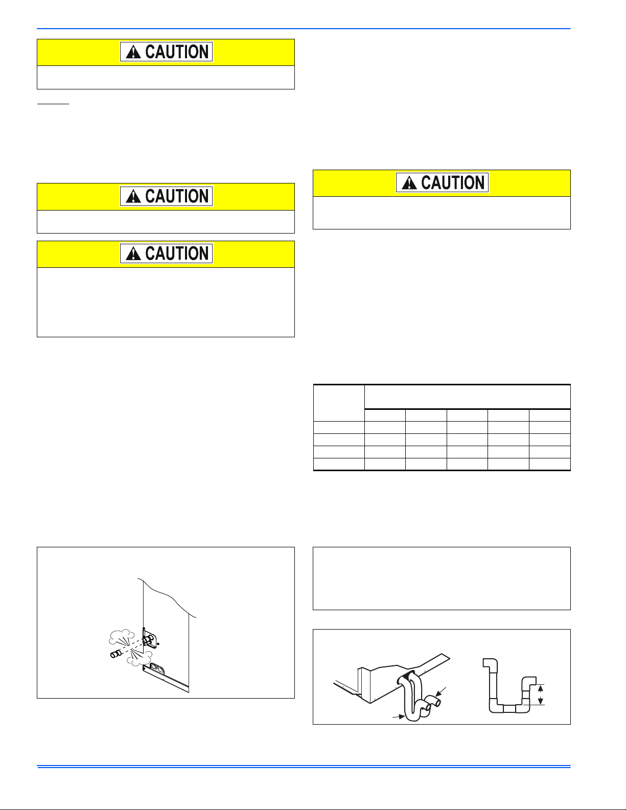
Coil is under inert gas pressure. Relieve pressure from coil by
removing rubber plug.
Dry nitrogen should always be supplied through the tubing while it
is being brazed, because the temperature required is high enough
to cause oxidation of the copper unless an inert atmosphere is pro-
vided. The flow of dry nitrogen should continue until the joint has
cooled. Always use a pressure regulator and safety valve to insure
that only low pressure dry nitrogen is introduced into the tubing.
Only a small flow is necessary to displace air and prevent oxidation.
Coil cleaning solutions must be diluted according to the manufac-
turer’s instructions. The use of undiluted coil cleaning solutions on
the coil WILL damage the coil coating.
TABLE 4:
Air Flow Data - Static Pressure Drop
HD Coil
Size
CFM @ Static Pressure Drop - IWG
(Based on wet coil)
0.10 0.15 0.20 0.25 0.30
24 360 560 760 960 1160
36 1025 1150 1275 1400 1525
48 1200 1367 1533 1700 1867
60 1449 1664 1879 2093 2308
FIGURE 6:
Pressure Check
Was the coil still under pressure
when received?
Pull rubber plug
to check for
pressure one time.
FIGURE 7:
TXV Check List
FIGURE 8:
Drain Traps
Is coil metering device installed correctly?
Was the correct TXV installed per the outdoor unit instructions?
Is the TXV Bulb positioned correctly?
Is Bulb Insulated?
Is Equalizer Line connected?
SECONDARY
PRIMARY
3” MIN
Were the primary and secondary
drains trapped correctly?

This manual suits for next models

3

Other York Heat Pump manuals

York SUNLINE 2000 B2CH180 User manual

York

York SUNLINE 2000 B2CH180 User manual

York E2FB120 User manual

York

York E2FB120 User manual

York EA090 Quick start guide

York

York EA090 Quick start guide

York SUNLINE 2000 BP 072 Quick start guide

York

York SUNLINE 2000 BP 072 Quick start guide

York SPLIT-SYSTEM YHJD18 THRU 60 Quick start guide

York

York SPLIT-SYSTEM YHJD18 THRU 60 Quick start guide

York YVJC09DS-AAA User manual

York

York YVJC09DS-AAA User manual

York YLUA0248 Series Owner's manual

York

York YLUA0248 Series Owner's manual

York SUNLINE 2000 B1CH180 User manual

York

York SUNLINE 2000 B1CH180 User manual

York YAFS018 User manual

York

York YAFS018 User manual

York DFAA User manual

York

York DFAA User manual

York YD480 Series User manual

York

York YD480 Series User manual

York E1RA Series User manual

York

York E1RA Series User manual

York BP 180 Quick start guide

York

York BP 180 Quick start guide

York YAST026 User manual

York

York YAST026 User manual

York YHJF18 Quick start guide

York

York YHJF18 Quick start guide

York YZB018 THRU 060 Quick start guide

York

York YZB018 THRU 060 Quick start guide

York YCUL0045 Owner's manual

York

York YCUL0045 Owner's manual

York AFFINITY YZB User manual

York

York AFFINITY YZB User manual

York YAFS012 User manual

York

York YAFS012 User manual

York PHE6B36 User manual

York

York PHE6B36 User manual

York PHG6A24 Quick start guide

York

York PHG6A24 Quick start guide

York YAWT100 User manual

York

York YAWT100 User manual

York YAZS022 User manual

York

York YAZS022 User manual

York YZE024 THRU 060 Quick start guide

York

York YZE024 THRU 060 Quick start guide

Popular Heat Pump manuals by other brands

Danfoss BW10 020-090 Operation instructions

Danfoss

Danfoss BW10 020-090 Operation instructions

Jula 416-081 operating instructions

Jula

Jula 416-081 operating instructions

Viessmann VITOCAL 300-G operating instructions

Viessmann

Viessmann VITOCAL 300-G operating instructions

Riello A2WHPR32M/004 manual

Riello

Riello A2WHPR32M/004 manual

Lennox HSXA15 SERIES installation instructions

Lennox

Lennox HSXA15 SERIES installation instructions

Nordyne T5BP Series User's manual & installation instructions

Nordyne

Nordyne T5BP Series User's manual & installation instructions

ClimateMaster Tranquility Technical guide

ClimateMaster

ClimateMaster Tranquility Technical guide

Kaisai KHY-12PY3 user manual

Kaisai

Kaisai KHY-12PY3 user manual

Novelan LI 14 operating manual

Novelan

Novelan LI 14 operating manual

Glen Dimplex LIH 10TE Installation and operating instruction

Glen Dimplex

Glen Dimplex LIH 10TE Installation and operating instruction

NextE CCE07 Installation, operation and maintenance guide

NextE

NextE CCE07 Installation, operation and maintenance guide

CLIVET WSAN-XEE Series Installation, use and maintenance manual

CLIVET

CLIVET WSAN-XEE Series Installation, use and maintenance manual

DeDietrich MIV-4S AWHP 6 MR-3 user guide

DeDietrich

DeDietrich MIV-4S AWHP 6 MR-3 user guide

Ferroli RXA-I PLUS Series user manual

Ferroli

Ferroli RXA-I PLUS Series user manual

Templari KITA ARIA Installation and maintenance manual

Templari

Templari KITA ARIA Installation and maintenance manual

Carrier OMNIZONE 50BV020-064 Installation and service instructions

Carrier

Carrier OMNIZONE 50BV020-064 Installation and service instructions

Oilon Geopro RE Operation manual

Oilon

Oilon Geopro RE Operation manual

Baxi Geoflo Operation, installation & maintenance instructions

Baxi

Baxi Geoflo Operation, installation & maintenance instructions

manuals.online logo
manuals.online logoBrands
  • About & Mission
  • Contact us
  • Privacy Policy
  • Terms and Conditions

Copyright 2025 Manuals.Online. All Rights Reserved.