York YLPA 0115SE User manual

Products are produced at a
f a c i l i t y w h o s e q u a l i t y -
management systems are
ISO9001 certified.
MODEL YLPA AIR TO LIQUID
REVERSIBLE SCROLL HEAT PUMPS
STYLE B
Cooling Capacities: 115 Tons to 170 Tons
Cooling Capacities: 400 kW to 600 kW
Heating Capacities:1390 MBH to 2040 MBH
Heating Capacities: 400 kW to 600 kW
60Hz
HFC-410A
Issue Date:
October 15, 2020
035-23346-100
YLPA 0115SE, 0145SE, 0170SE
INSTALLATION, OPERATION AND
MAINTENANCE Supersedes: 150.68-ICOM1 (1217) FORM 150.68-ICOM1 (1020)

2JOHNSON CONTROLS
FORM 150.68-ICOM1
ISSUE DATE: 10/15/2020
This equipment is a relatively complicated apparatus.
During rigging, installation, operation, maintenance,
or service, individuals may be exposed to certain com-
ponents or conditions including, but not limited to:
heavy objects, refrigerants, materials under pressure,
rotating components, and both high and low voltage.
Each of these items has the potential, if misused or
handled improperly, to cause bodily injury or death. It
is the obligation and responsibility of rigging, instal-
lation, and operating/service personnel to identify and
recognize these inherent hazards, protect themselves,
and proceed safely in completing their tasks. Failure
to comply with any of these requirements could result
in serious damage to the equipment and the property in
IMPORTANT!
Read BEFORE PROCEEDING!
GENERAL SAFETY GUIDELINES
which it is situated, as well as severe personal injury or
death to themselves and people at the site.
This document is intended for use by owner-authorized
rigging, installation, and operating/service personnel. It
is expected that these individuals possess independent
training that will enable them to perform their assigned
tasks properly and safely. It is essential that, prior to
performing any task on this equipment, this individual
shall have read and understood the on-product labels,
this document and any referenced materials. This in-
dividual shall also be familiar with and comply with
all applicable industry and governmental standards and
regulations pertaining to the task in question.
SAFETY SYMBOLS
The following symbols are used in this document to alert the reader to areas of potential hazard:
CAUTION identies a hazard which could
lead to damage to the machine, damage
to other equipment and/or environmental
pollution. Usually an instruction will be
given, together with a brief explanation.
NOTE is used to highlight additional
information which may be helpful to you.
DANGER indicates an imminently
hazardous situation which, if not avoided,
will result in death or serious injury.
WARNING indicates a potentially hazardous
situation which, if not avoided, could result
in death or serious injury.
External wiring, unless specied as an optional connection in the manufacturer’s product line, is
not to be connected inside the micro panel cabinet. Devices such as relays, switches, transducers
and controls may not be installed inside the panel. No external wiring is allowed to be run through
the micro panel. All wiring must be in accordance with YORK’s published specications and must
be performed only by qualied YORK personnel. YORK will not be responsible for damages/
problems resulting from improper connections to the controls or application of improper control
signals. Failure to follow this will void the manufacturer’s warranty and cause serious damage to
property or injury to persons.

3
JOHNSON CONTROLS
FORM 150.68-ICOM1
ISSUE DATE: 10/15/2020
The Control Cabinet contains lethal AC and DC voltages. Before performing service inside
the cabinet, remove the AC supply feeding the chiller.
The DC Voltage on the DC Bus will take 5 minutes to bleed o, after
AC power is removed. Always check the DC Bus Voltage with a
Voltmeter to assure the capacitor charge has bled o before working
on the system.
NEVER short out the DC Bus to discharge the lter capacitors.
NEVER place loose tools, debris, or any objects inside the Control Panel Cabinet.
NEVER allow the Control Panel Cabinet doors to remain open if there is a potential for rain
to enter the panel. Keep doors closed and assure all latches are engaged on each door
unless the unit is being serviced.
WARNING!
CHANGEABILITY OF THIS DOCUMENT
In complying with Johnson Controls’ policy for con-
tinuous product improvement, the information con-
tained in this document is subject to change without
notice. Johnson Controls makes no commitment to
update or provide current information automatically
to the manual or product owner. Updated manuals, if
applicable, can be obtained by contacting the nearest
Johnson Controls Service office or accessing the John-
son Controls Knowledge Exchange website at https://
docs.johnsoncontrols.com/chillers/.
It is the responsibility of rigging, lifting, and operating/
service personnel to verify the applicability of these
documents to the equipment. If there is any question
regarding the applicability of these documents, rig-
ging, lifting, and operating/service personnel should
verify whether the equipment has been modified and
if current literature is available from the owner of the
equipment prior to performing any work on the chiller.
REVISION NOTES
Revisions made to this document are indicated in the following table. These revisions are to technical information,
and any other changes in spelling, grammar, or formatting are not included.
AFFECTED PAGES DESCRIPTION
3 Conditioned Based Maintenance program information added
CONDITIONED BASED MAINTENANCE
Traditional chiller maintenance is based upon assumed
and generalized conditions. In lieu of the traditional
maintenance program, a Johnson Controls YORK
Conditioned Based Maintenance (CBM) program can
be substituted. This CBM service plan is built around
the specific needs for the chiller, operating conditions,
and annualized impact realized by the chiller. Your lo-
cal Johnson Controls Branch can propose a customized
Planned Service Agreement that leverages real time
and historical data, delivering performance reporting,
corrective actions required and data enabled guidance
for optimal operation and lifecycle assurance. The pro-
gram will include fault detection diagnostics, operation
code statistics, performance based algorithms and ad-
vance rules based rationale delivered by the Johnson
Controls Connected Equipment Portal.

4JOHNSON CONTROLS
FORM 150.68-ICOM1
ISSUE DATE: 10/15/2020
Page Left Intentionally Blank

5
JOHNSON CONTROLS
FORM 150.68-ICOM1
ISSUE DATE: 10/15/2020
TABLE OF CONTENTS
GENERAL INFORMATION & SAFETY
INTRODUCTION ............................................. 7
WARRANTY...................................................... 7
SAFETY.............................................................. 7
FLUORINATED GREENHOUSE GASES..... 7
RESPONSIBILITY FOR SAFETY.................. 8
ABOUT THIS MANUAL ................................. 8
MISUSE OF EQUIPMENT .............................. 8
PRODUCT DESCRIPTION
INTRODUCTION ........................................... 11
COMPRESSORS ............................................. 11
REFRIGERANT CIRCUITS.......................... 11
REFRIGERANT TO WATER HEAT
EXCHANGER ................................................. 11
AMBIENT COILS........................................... 11
POWER AND CONTROLS PANELS........... 12
MICROPROCESSOR CONTROLS .............. 12
ACCESSORIES AND OPTIONS .................. 13
REFRIGERANT FLOW BLOCK
DIAGRAMS..................................................... 14
COMPONENT LOCATION DIAGRAM ...... 15
NOMENCLATURE......................................... 15
HANDLING AND STORAGE
DELIVERY AND STORAGE ........................ 17
INSPECTION................................................... 17
MOVING THE UNIT...................................... 17
LIFTING WEIGHTS....................................... 18
INSTALLATION
LOCATION REQUIREMENTS..................... 19
OUTDOOR INSTALLATIONS ..................... 19
LOCATION CLEARANCES.......................... 19
INSTALLATION OF VIBRATION
ISOLATORS..................................................... 21
PIPEWORK CONNECTION ......................... 21
PIPEWORK ARRANGEMENT..................... 21
CHILLED LIQUID SYSTEM........................ 22
CONNECTION TYPES AND SIZES............ 22
WATER TREATMENT ................................... 22
WATER QUALITY REQUIREMENTS ........ 22
REFRIGERANT RELIEF VALVE PIPING.. 22
ELECTRICAL CONNECTION ..................... 23
POWER WIRING............................................ 23
SINGLE POINT POWER SUPPLY
WIRING............................................................ 23
CONTROL CIRCUIT TRANSFORMER...... 23
REMOTE EMERGENCY STOP DEVICE ... 23
CONTROL WIRING - VOLTAGE FREE
CONTACT........................................................ 23
CHILLED LIQUID PUMP STARTER .......... 23
RUN CONTACTS............................................ 24
ALARM CONTACTS ..................................... 24
CONTROL WIRING - SYSTEM INPUTS ... 24
FLOW SWITCH .............................................. 24
REMOTE START/STOP................................. 24
REMOTE MODE SELECTION..................... 24
REMOTE RESET OF CHILLED LIQUID
SETPOINT ....................................................... 24
REMOTE LOAD LIMITING ......................... 24
FAN FULL SPEED INHIBIT ......................... 24
EMS ANALOGUE INPUT ............................. 24
MODBUS, BACNET MS/TP AND N2.......... 24
CONNECTION DIAGRAM........................... 25
COMMISSIONING
PREPARATION ............................................... 27
PREPARATION - POWER OFF .................... 27
FIRST TIME START-UP................................. 28
OPERATION
CONTROL PANEL KEYS.............................. 31
STATUS KEY................................................... 31
DISPLAY/PRINT KEYS................................. 36
ENTRY KEYS.................................................. 42
SETPOINTS KEYS......................................... 42
UNIT KEYS ..................................................... 48
OPTIONAL PRINTER INSTALLATION..... 51
BAS/EMS TEMPERATURE RESET ............ 51
BACNET, MODBUS AND YORKTALK 2
COMMUNICATIONS..................................... 55
MAINTENANCE
GENERAL REQUIREMENTS ...................... 67
DAILY MAINTENANCE............................... 67
SCHEDULED MAINTENANCE .................. 68
HEAT EXCHANGER IN-SERVICE
INSPECTION................................................... 68
COMPETENT PERSONS TROUBLE
SHOOTING GUIDE........................................ 69
SENSOR CALIBRATION CHARTS............. 71

6JOHNSON CONTROLS
FORM 150.68-ICOM1
ISSUE DATE: 10/15/2020
TECHNICAL DATA
WATERSIDE PRESSURE DROP GRAPH
OF EVAPORATORS ....................................... 73
OPERATING LIMITATIONS ........................ 74
PHYSICAL DATA........................................... 74
ELECTRICAL DATA...................................... 75
SOUND DATA................................................. 75
ISOLATOR DATA ........................................... 80
ONE INCH DEFLECTION SPRING
ISOLATORS CROSS REFERENCE............. 80
ONE INCH DEFLECTION SPRING
ISOLATORS INSTALLATION
INSTRUCTIONS............................................. 81
TWO INCH DEFLECTION SPRING
ISOLATORS CROSS REFERENCE............. 82
TWO INCH DEFLECTION SPRING
ISOLATORS INSTALLATION AND
ADJUSTMENT................................................ 83
DURALENE ISOLATOR CROSS
REFERENCE ................................................... 84
DURULENE ISOLATORS
INSTALLATION ............................................. 85
SPARE PARTS
RECOMMENDED SPARES .......................... 87
RECOMMENDED COMPRESSOR OIL...... 87
ASSOCIATED DRAWINGS .......................... 87
DECOMMISSIONING, DISMANTLING AND
DISPOSAL

7
JOHNSON CONTROLS
FORM 150.68-ICOM1
ISSUE DATE: 10/15/2020
GENERAL INFORMATION & SAFETY
INTRODUCTION
YORK YLPA units are manufactured to the highest
design and construction standards to ensure high
performance, reliability and adaptability to all types of
air conditioning installations.
The unit is intended for cooling and heating water or
glycol solutions and is not suitable for purposes other
than those specied in this manual.
This manual contains all the information required for
correct installation and commissioning of the unit,
together with operating and maintenance instructions.
The manuals should be read thoroughly before
attempting to operate or service the unit.
All procedures detailed in this manual, including
installation, commissioning and maintenance tasks must
only be performed by suitably trained and qualied
personnel.
The manufacturer will not be liable for any injury or
damage caused by incorrect installation, commissioning,
operation or maintenance resulting from a failure to
follow the procedures and instructions detailed in the
manuals.
WARRANTY
Johnson Controls warrants all equipment and materials
against defects in workmanship and materials for a
period of eighteen months from date of shipment, unless
labor or extended warranty has been purchased as part
of the contract.
The warranty is limited to parts only replacement and
shipping of any faulty part, or sub-assembly, which has
failed due to poor quality or manufacturing errors. All
claims must be supported by evidence that the failure has
occurred within the warranty period, and that the unit has
been operated within the designed parameters specied.
All warranty claims must specify the unit model, serial
number, order number and run hours/starts. Model
and serial number information is printed on the unit
identication plate.
The unit warranty will be void if any modication to
the unit are carried out without prior written approval
from Johnson Controls.
For warranty purposes, the following conditions must
be satised:
• The initial start of the unit must be carried out by
trained personnel from an Authorized Johnson
Controls Service Center.
• Only genuine Johnson Controls approved spare
parts, oils, coolants, and refrigerants must be used.
• All the scheduled maintenance operations detailed
in this manual must be performed at the specied
times by suitably trained and qualied personnel.
• Failure to satisfy any of these conditions will au-
tomatically void the warranty.
SAFETY
Standards for Safety
YLPA units are designed and manufactured within an
EN ISO 9001 accredited organization and in conformity
with the following Standards and Codes:
• ANSI/ASHRAE Standard 15, Safety Code for
Mechanical Refrigeration.
• ANSI/NFPA Standard 70, National Electrical Code
(N.E.C.).
• ASME Boiler and Pressure Vessel Code, Section VIII
Division 1.
• ARI Standard 550/590-98, Water Chilling Packages
Using the Vapor Compression Cycle.
• ASHRAE 90.1 Energy Standard for Building Except
Low-Rise Residential Buildings.
• ARI 370 Sound Rating of Large Outdoor Refrigeration
and Air Conditioning Equipment.
In addition, the chillers conform to Underwriters
Laboratories (U.L.) for construction of chillers and
provide U.L./cU.L. Listing Label.
FLUORINATED GREENHOUSE GASES
• This equipment contains uorinated greenhouse gases
covered by the Kyoto Protocol.
• The global warming potential of the refrigerant
(R-410A) used in this unit is 2088.
• The refrigerant quantity is stated in the Physical Data
table.
• The uorinated greenhouse gases in this equipment
may not be vented to the atmosphere.
• This equipment should only be serviced by qualied
technicians.

8JOHNSON CONTROLS
FORM 150.68-ICOM1
ISSUE DATE: 10/15/2020
RESPONSIBILITY FOR SAFETY
Every care has been taken in the design and manufacture
of the unit to ensure compliance with the safety
requirements listed above. However, the individual
operating or working on any machinery is primarily
responsible for:
• Personal safety, safety of other personnel, and the
machinery.
• Correct utilization of the machinery in accordance with
the procedures detailed in the manuals.
ABOUT THIS MANUAL
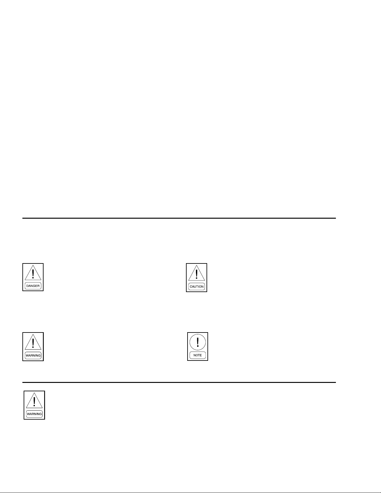
The following terms are used in this document to alert
the reader to areas of potential hazard.
A WARNING is given in this document to
identify a hazard, which could lead to
personal injury. Usually an instruction will
be given, together with a brief explanation
and the possible result of ignoring the
instruction.
A CAUTION identies a hazard which could
lead to damage to the machine, damage to
other equipment and/or environmental
pollution. Usually an instruction will be
given, together with a brief explanation and
the possible result of ignoring the
instruction.
A NOTE is used to highlight additional
information, which may be helpful to you
but where there are no special safety
implications.
The contents of this manual include suggested best
working practices and procedures. These are issued for
guidance only, and they do not take precedence over
the above stated individual responsibility and/or local
safety regulations.
This manual and any other document supplied with the
unit are the property of YORK which reserves all rights.
They may not be reproduced, in whole or in part, without
prior written authorization from an authorized YORK
representative.
MISUSE OF EQUIPMENT
Suitability for Application
The unit is intended for cooling water or glycol solutions
and is not suitable for purposes other than those specied
in these instructions. Any use of the equipment other
than its intended use, or operation of the equipment
contrary to the relevant procedures may result in injury
to the operator, or damage to the equipment.
The unit must not be operated outside the design
parameters specied in this manual.
Structural Support
Structural support of the unit must be provided as
indicated in these instructions. Failure to provide proper
support may result in injury to the operator, or damage
to the equipment and/or building.
Mechanical Strength
The unit is not designed to withstand loads or stresses
from adjacent equipment, pipework or structures.
Additional components must not be mounted on the unit.
Any such extraneous loads may cause structural failure
and may result in injury to the operator, or damage to
the equipment.
General Access
There are a number of areas and features, which may
be a hazard and potentially cause injury when working
on the unit unless suitable safety precautions are taken.
It is important to ensure access to the unit is restricted
to suitably qualied persons who are familiar with the
potential hazards and precautions necessary for safe
operation and maintenance of equipment containing
high temperatures, pressures and voltages.
Pressure Systems
The unit contains refrigerant vapor and liquid under
pressure, release of which can be a danger and cause
injury. The user should ensure that care is taken during
installation, operation and maintenance to avoid damage
to the pressure system. No attempt should be made
to gain access to the component parts of the pressure
system other than by suitably trained and qualied
personnel.
Electrical
The unit must be earthed. No installation or maintenance
work should be attempted on the electrical equipment
without rst switching power OFF, isolating and locking-
o the power supply. Servicing and maintenance on live
equipment must only be performed by suitably trained
and qualied personnel. No attempt should be made to
gain access to the Control Panel or electrical enclosures
during normal operation of the unit.
Rotating Parts
Fan guards must be tted at all times and not removed
unless the power supply has been isolated. If ductwork is
to be tted, requiring the wire fan guards to be removed,
alternative safety measures must be taken to protect
against the risk of injury from rotating fans.

9
JOHNSON CONTROLS
FORM 150.68-ICOM1
ISSUE DATE: 10/15/2020
Sharp Edges
The ns on the air-cooled condenser coils have sharp
metal edges. Reasonable care should be taken when
working in contact with the coils to avoid the risk of
minor abrasions and lacerations. The use of gloves is
recommended.
Frame rails, braces, and other components may also
have sharp edges. Reasonable care should be taken when
working in contact with any components to avoid risk
of minor abrasions and lacerations.
Refrigerants and Oils
Refrigerants and oils used in the unit are generally
nontoxic, non-ammable and non-corrosive, and pose
no special safety hazards. However, the use of gloves
and safety glasses are recommended when working on
the unit. The build up of refrigerant vapor, from a leak
for example, does pose a risk of asphyxiation in conned
or enclosed spaces and attention should be given to good
ventilation.
High Temperature and Pressure Cleaning
High temperature and pressure cleaning methods (e.g.
steam cleaning) should not be used on any part of the
pressure system as this may cause operation of the
pressure relief device(s). Detergents and solvents, which
may cause corrosion, should also be avoided.
Emergency Shutdown
In case of emergency, the non-fused disconnect switch
on the power panel should be used as the emergency stop
device. When operated it removes the electrical supply
to the unit thus shutting down the unit.
Safety Labels
The following labels are xed to each unit to give
instruction, or to indicate potential hazards which may
exist.
White symbol on blue background
For safe operation, read the instructions
rst.
Black symbol on yellow background.
Warning: This machine may start
automatically without prior warning.
Black symbol on yellow background
Warning: Hot surface.
Black symbol on yellow background
Warning: Safety relief valve may discharge
gas or liquid without prior warning.
Black symbol on yellow background
Warning: Isolate all electrical sources of
supply before opening or removing the
cover, as lethal voltages may exist.
Black symbol on yellow background
General attention symbol.
Black symbol on yellow background
Warning: On isolating the supply it may
take up to 300 seconds for the capacitor
voltage to fall below 50 volts.

10 JOHNSON CONTROLS
FORM 150.68-ICOM1
ISSUE DATE: 10/15/2020
Page Left Intentionally Blank

11
JOHNSON CONTROLS
FORM 150.68-ICOM1
ISSUE DATE: 10/15/2020
PRODUCT DESCRIPTION
compressors are mounted on isolator pads to reduce
transmission of vibration to the rest of the unit.
The motor terminal boxes have IP54 weather protection.
REFRIGERANT CIRCUITS
Two independent refrigerant circuits are provided on
each unit. Each circuit uses copper refrigerant pipe
formed on computer controlled bending machines to
reduce the number of brazed joints resulting in a high
integrity and reliable system.
Each circuit shall incorporate all components necessary
for the designed operation including: a suction
accumulator, a liquid receiver, a four way reversing
valve, service valves, isolation (ball/angle) valves,
pressure relief valves, a high absorption removable
core lter-drier, a sight glass with moisture indicator,
and an electronic expansion valve. Suction lines shall
be covered with closed-cell insulation.
REFRIGERANT TO WATER HEAT EXCHANGER
The 2-pass dual circuit shell and tube type direct
expansion (DX) heat exchanger has refrigerant in the
tubes and liquid owing through the baed shell. The
waterside (shell) design working pressure is 150 psig.
The refrigerant side (tubes) design working pressure is
650 psig. The refrigerant side is protected by pressure
relief valve(s).
The heat exchanger is equipped with a heater for frost
protection to -4°F (below this the ball valve in the
discharge line must be closed) and insulated with exible
closed-cell foam.
Water connection to the heat exchanger is via victaulic
grooved connections. Victaulic groove to flange
converters are available as an option.
AMBIENT COILS
The ambient coils are seamless copper tubes, arranged
in staggered rows, mechanically expanded into coated
aluminium ns. Integral sub-cooling is included.
The ambient coil fans are designed for maximum
efficiency and statically and dynamically balanced
for vibration free operation. They are directly driven
by independent motors, and positioned for vertical air
discharge. The fan guards are constructed from heavy-
gauge, corrosion resistant, coated steel.
INTRODUCTION
YLPA air-to-liquid heat pumps are completely factory
assembled with all interconnecting refrigerant piping and
wiring ready for eld installation. The unit is pressure
tested, evacuated, and fully factory charged with
refrigerant R-410A and oil in each of the independent
refrigerant circuits. After assembly, an operational
test is performed with water owing through the heat
exchanger to ensure that each refrigerant circuit operates
correctly.
The unit structure is manufactured from heavy-gauge,
galvanized steel coated with baked-on powder paint
(Champagne (RAL 7006, Munsell No. 9.8YR4.36/1.2)).
YLPA units are designed and manufactured within an
EN ISO 9001 accredited organization and in conformity
with the following Standards and Codes:
• ANSI/ASHRAE Standard 15, Safety Code for
Mechanical Refrigeration.
• ANSI/NFPA Standard 70, National Electrical Code
(N.E.C.).
• ASME Boiler and Pressure Vessel Code, Section VIII
Division 1.
• ARI Standard 550/590-98, Water Chilling Packages
Using the Vapor Compression Cycle.
• ASHRAE 90.1 Energy Standard for Building Except
Low-Rise Residential Buildings.
• ARI 370 Sound Rating of Large Outdoor Refrigeration
and Air Conditioning Equipment.
In addition, the chillers conform to Underwriters
Laboratories (U.L.) for construction of chillers and
provide U.L./cU.L. Listing Label.
COMPRESSORS
The YLPA unit has suction-cooled, hermetic scroll
compressors. High eciency is achieved through a
controlled orbit and the use of advanced scroll geometry.
The compressors incorporate a compliant scroll design
in both the axial and radial directions. All rotating parts
are statically and dynamically balanced. The compressor
motors have integral protection against overloads that
will automatically reset. Starting is direct on line, and
soft start is available as an option.
The compressors are switched On and O by the unit
microprocessor to provide capacity control. Each
compressor is tted with a crankcase strap heater. All

12 JOHNSON CONTROLS
FORM 150.68-ICOM1
ISSUE DATE: 10/15/2020
The IP54 fan motors are the totally enclosed air-over
type with permanently lubricated double-sealed ball
bearings.
POWER AND CONTROLS PANELS
All power and controls are contained in an IP 55 cabinet
with hinged and gasket sealed outer doors.
The power panel includes:
• A factory mounted non-fused disconnect switch
with external (red/yellow) lockable handle to enable
connection of the unit power supply. The disconnect
switch can be used to isolate the power for servicing
and as a emergency stop.
• Factory mounted compressor contactors and
compressor fuses provide short circuit protection.
Overload protection for each compressor is provided
by inherent motor winding temperature sensing and
a trip module.
• Factory mounted fan contactors and fuses provide
short circuit protection. Overload protection for
each fan is provided by a inherent motor winding
temperature device.
• Factory mounted control transformer to convert the
unit supply voltage to 115 V - 1 Ø - 60 Hz for the
control system.
• Control supply fuses and connections for a remote
emergency stop device.
The control panel includes:
• A Liquid Crystal Display (two display lines of twenty
characters per line) with Light Emitting Diode
backlighting for easy viewing.
• A Color coded 12-button keypad.
• Customer terminal blocks for control inputs and liquid
ow switch.
MICROPROCESSOR CONTROLS
The microprocessor control includes:
• Automatic control of compressor start/stop,
anticoincidence and anti-recycle timers, pump and
unit alarm contacts. Automatic reset to normal unit
operation after power failure.
• Remote water temperature setpoint reset via an analog
input or a pulse width modulated (PWM) input signal,
or up to two steps of demand (load) limiting.
• Software is loaded into the microprocessor controller
via a SD card, with programmed setpoints retained in a
lithium battery backed real time clock (RTC) memory.
• Forty character liquid crystal display, with description
available in several languages.
Programmable setpoints:
• Chilled liquid temperature setpoint and range
• Hot liquid temperature setpoint and range
• Remote reset temperature range
• Set daily schedule/holiday for start/stop
• Manual override for servicing
• Low ambient cutout
• High ambient cutout (heating only - xed)
• Low liquid temperature cutout
• Low suction pressure cutout
• High discharge pressure cutout
• Anti-recycle timer (compressor start cycle time)
• Anti-coincident timer (delay compressor starts)
• Cooling suction superheat
• Heating suction superheat
Displayed Data:
• Leaving liquid temperature
• Air coil defrost temperatures
• Low leaving liquid temperature cutout setting
• Low ambient temperature cutout setting
• EEV output
• Suction superheat
• Suction temperature
• Suction saturated temperature
• Ambient air temperature
• Metric or Imperial data
• Discharge and suction pressure cutout settings
• System discharge and suction pressures
• Anti-recycle timer status for each system
• Anti-coincident system start timer condition

13
JOHNSON CONTROLS
FORM 150.68-ICOM1
ISSUE DATE: 10/15/2020
• Compressor run status
• No load condition
• Day, date and time
• Daily start/stop times
• Holiday status
• Automatic or manual system lead/lag control
• Lead system denition
• Compressor starts & operating hours (each compressor)
• Status of heat exchanger heater and fan operation
• Run permissive status
• Number of compressors running
• Mode solenoid valve status
• Load & unload timer status
• Liquid pump status
System Safeties:
Cause individual compressors to perform auto shut
down and require manual reset in the event of 3 trips in
a 90-minute time period:
• High discharge pressure
• Low suction pressure
• Low suction superheat
• High-pressure switches
• Motor protector
Unit Safeties:
They are automatic reset and cause compressor to shut
down:
• Low leaving chilled liquid temperature
• Under voltage
• Loss of liquid ow (through ow switch)
For each system a common alarm contact for:
• Low leaving chilled liquid temperature
• Low voltage
• Low battery
• High discharge pressure (per system)
• Low suction pressure (per system)
• Compressor motor protection
ACCESSORIES AND OPTIONS
Flow Switch
The ow switch or its equivalent must be furnished with
each unit. 150 psig (10.5 bar) DWP - For standard units.
Johnson Controls model F61MG-1C Vapor-proof SPDT,
NEMA 3R switch (150 PSIG [10.5 bar] DWP), -20°F
to 250°F (-29°C to 121°C), with 1” NPT connection for
upright mounting in horizontal pipe. (Field-mounted)
Chicago Code Relief Valves
The unit will be provided with relief valves to meet
Chicago code requirements. (Factory mounted)
Neoprene Pads Isolators
Recommended for normal installations (Field mounted)
1" Spring Isolators
Level adjustable, spring and cage type isolators for
mounting under the unit base rails (Field mounted)
2" Spring Isolators
Restrained Spring-Flex Mountings incorporating a
rugged welded steel housing with vertical and horizontal
limit stops. (Field mounted)
Flange Kit
Provides contractor with the couplings best suited to
tie into the chilled water piping. All anges are PN10.
Single-Point Supply Terminal Block
Includes enclosure, terminal-block and interconnecting
wiring to the compressors. Separate external protection
must be supplied, by others, in the incoming compressor-
power wiring. (Do not include this option if either the
Single-Point Non-Fused Disconnect Switch or Single-
Point Circuit Breaker options have been included.)
Single-Point Circuit Breaker
A unit mounted circuit breaker with external, lockable
handle (in compliance with N.E.C. Article 440-14), can
be supplied to isolate the power voltage for servicing.
This option includes the Single-Point Power connection.

14 JOHNSON CONTROLS
FORM 150.68-ICOM1
ISSUE DATE: 10/15/2020
REFRIGERANT FLOW BLOCK DIAGRAMS
Cooling and Defrost Modes
Low pressure liquid refrigerant enters the heat exchanger and is evaporated and superheated by the heat energy
absorbed from the chilled liquid. Low pressure vapor enters the compressor, via the four-way reversing valve and
accumulator, where pressure and superheat are increased. The high pressure vapor is fed to the ambient coils and
fans, via the four way reversing valve, where heat is removed. The fully condensed and subcooled liquid passes
through the electronic expansion valve where pressure is reduced and further cooling takes place before returning
to the heat exchanger.
Heat Pump Mode
Liquid refrigerant enters the ambient coil, and is fully evaporated and superheated by the energy absorbed from the
ambient air. Low-pressure superheated refrigerant vapor passes through the four-way reversing valve and the
accumulator and enters the compressor, where pressure and superheat are increased. High-pressure superheated
refrigerant vapor enters the refrigerant to water plate heat exchanger where heat is rejected to the water. The high-
pressure liquid refrigerant, leaving the heat exchanger passes through the liquid receiver and enters the electronic
expansion valve where the refrigerant pressure is reduced and subsequently cooled before returning to the ambient
coil.
Defrost
When ice builds up on the ambient coils defrost is initiated by operating the machine in a cooling mode. Each of
the refrigerant circuits will be defrosted one at a time. When defrost is operative the circuit operating in heat pump
mode is in balance with the circuit operating in defrost (cooling). Therefore, heat energy is not removed from the
hot water system.
Ambient Coils
(Condenser)
Refrigerant flow
Compressors Heat Exchanger
(Evaporator)
4-way valve
Accumulator
Receiver
EEV
Ambient Coils
(Evaporator)
Refrigerant flow
Compressors
4-way valve
Accumulator
Receiver
Heat Exchanger
(Condenser)
EEV

15
JOHNSON CONTROLS
FORM 150.68-ICOM1
ISSUE DATE: 10/15/2020
COMPONENT LOCATION DIAGRAM
NOMENCLATURE
YLPA0115SE40XBB
1 2 3 4 5 6 7 8 9 10 11 12 13 14 15
BASE PRODUCT TYPE NOMINAL CAPACITY UNIT DESIGNATION REFRIGERANT VOLTAGE / STARTER DESIGN / DEVELOPMENT LEVELS
YLPA
# # # # kW S : Standard Unit E : R-410A B
0115 0145 0170
: York
: Scroll
: Heat Pump
: All Regions
: Design Series
: Development Level
B
4 6 x : 460/3/60
1 7 x : 200/3/60
2 8 x : 230/3/60
4 0 x : 380/3/60
5 8 x : 575/3/60
1
2
3
8
5
4
6
7
1Power Panel 5Heat Exchanger
2Non-Fused Disconnect Switch 6Suction Accumulator
3Control Panel 7Ambient Coils
4Compressors 8Fans
LD23120

16 JOHNSON CONTROLS
FORM 150.68-ICOM1
ISSUE DATE: 10/15/2020
Page Left Intentionally Blank

17
JOHNSON CONTROLS
FORM 150.68-ICOM1
ISSUE DATE: 10/15/2020
HANDLING AND STORAGE
DELIVERY AND STORAGE
To ensure consistent quality and maximum reliability,
all units are tested and inspected before leaving the
factory. Units are shipped completely assembled and
contain refrigerant under pressure. Units are shipped
without export crating unless crating has been specied
on the Sales Order.
If the unit is to be put into storage, prior to installation,
the following precautions should be observed:
• Ensure that all openings, such as water connec-
tions are securely capped.
• The unit should be stored in a location where there
is minimal activity in order to limit the risk of ac-
cidental physical damage.
• To prevent inadvertent operation of the pressure
relief devices, the unit must not be steam cleaned.
• It is recommended that the unit is periodically in-
spected during storage.
INSPECTION
Remove any transit packing and inspect the unit to
ensure that all components have been delivered and that
no damage has occurred during transit. If any damage
is evident, it should be noted on the carrier’s freight bill
and a claim entered in accordance with the instructions
given on the advice note.
Major damage must be reported immediately to your
local Johnson Controls representative.
MOVING THE UNIT
Prior to moving the unit, ensure that the installation site
is suitable for installing the unit and is easily capable
of supporting the weight of the unit and all associated
services.
The unit should be lifted using lifting lugs and a spreader
bar or frame of sucient width to prevent damage to
the unit from the lifting chains.
The unit must only be lifted by the base
frame at the points provided. Never move
the unit on rollers, or lift the unit using a
fork-lift truck.
Care should be taken to avoid damaging
the ambient coil ns when moving the unit.
Units are provided with lifting holes in the base frame
which accept the accessory lifting lug set (part number
026L00261-000 - 4 lug set, 026-45594-000 - 6 lug set).
The lugs should be inserted into the respective holes in
the base frame and turned so that the spring loaded pin
engages into the hole and the anges on the lug lock
behind the hole. The lugs should be attached to the
cables/chains using shackles or safety hooks.

18 JOHNSON CONTROLS
FORM 150.68-ICOM1
ISSUE DATE: 10/15/2020
LIFTING WEIGHTS
The weights and weight distribution limits are given below.
Model Shipping Operating R1 R2 R3 R4 L1 L2 L3 L4
0115SE 9811 10472 1864 1026 1414 2178 1822 2168
0145SE 11243 11904 1021 1471 1024 1356 1595 2191 1541 1705
0170SE 12124 13447 1068 1545 1642 1279 1595 2257 2479 1582
Weight (lbs)
Point Weight (lbs)
R1
R2
R3
R4
L1
L2
L3
L4
Control Panel

19
JOHNSON CONTROLS
FORM 150.68-ICOM1
ISSUE DATE: 10/15/2020
INSTALLATION
LOCATION REQUIREMENTS
To achieve optimum performance and trouble-free
service, it is essential that the proposed installation site
meet with the location and space requirements for the
model being installed.
The clearances recommended are nominal for the safe
and ecient operation and maintenance of the unit
and power and control panels. Local health and safety
regulations, or practical considerations for service
replacement of large components, may require larger
clearances than those given in this manual.
OUTDOOR INSTALLATIONS
The units can be installed at ground level on a suitable
and level foundation easily capable of supporting the
weight of the unit, or on a suitable rooftop location. In
both cases an adequate supply of air is required. Avoid
locations where the sound output and air discharge from
the unit may be objectionable.
The location should be selected for minimum sun
exposure and away from boiler ues and other sources
of airborne chemicals that could attack the ambient coils
and steel parts of the unit.
If located in an area accessible to unauthorized persons,
steps must be taken to prevent access to the unit by
means of a protective fence. This will help to prevent
the possibility of vandalism, accidental damage, or
possible harm caused by unauthorized removal of
protective guards or opening panels to expose rotating
or electrically live components.
For ground level locations, the unit must be installed
on a suitable at and level concrete base that extends
to fully support the two side channels of the unit
base frame. A one-piece concrete slab with footings,
extending below the frost line is recommended. To avoid
noise and vibration transmission, the unit should not be
secured to the building foundation.
On rooftop locations, choose a place with adequate
structural strength to safely support the entire operating
weight of the unit and service personnel. The unit can
be mounted on a concrete slab, similar to ground oor
locations, or on steel channels of suitable strength.
The channels should be spaced with the same centers
as the unit side and front base rails. This will allow
vibration isolators to be tted if required. Isolators are
recommended for rooftop locations.
LOCATION CLEARANCES
Adequate clearances around the unit(s) are required
for the unrestricted air-ow for the ambient coils and
to prevent re-circulation of discharge air back onto the
coils. If clearances given are not maintained, air-ow
restriction or re-circulation will cause a loss of unit
performance, an increase in power consumption, and
may cause the unit to malfunction. Consideration should
also be given to the possibility of down drafts, caused
by adjacent buildings, which may cause re-circulation
or uneven unit air-ow.
For locations where signicant cross winds are expected,
such as exposed roof tops, an enclosure of solid or
louvre type is recommended to prevent wind turbulence
interfering with the unit air-ow.
When units are installed in an enclosure, the enclosure
height should not exceed the height of the unit on more
than one side. Where accumulation of snow is likely,
additional height must be provided under the unit to
ensure normal air-ow to the unit.
0115SE 0145SE 0170SE
A47 47 47
B32 32 32
C32 39 47
D55 55 55
A47 47 47
B32 32 32
C32 39 47
D106 126 126
E55 55 55
A47 47 47
B32 32 32
C32 39 47
D91 118 126
E55 55 55
A47 47 47
B47 47 47
C32 32 32
D32 39 47
E67 75 83
A47 47 47
B47 47 47
C32 32 32
D32 32 32
E55 55 55
YLPA
Arrangement
A5
Louvres on
2 walls
Dim.
(in)
Arrangement
A1
Solid Walls
Arrangement
A2
Solid Walls
Arrangement
A3
Louvres on
2 walls
Arrangement
A4
Solid Walls

20 JOHNSON CONTROLS
FORM 150.68-ICOM1
ISSUE DATE: 10/15/2020
A1
A
B
C
D
E
A1
C
C
D
D
E
A
B
C
D
A1
A4
A
A
B
B
A2
A3
A5
A
B
C
DE
E
This manual suits for next models
2
Table of contents
Other York Heat Pump manuals

York
York PHE6B36 User manual

York
York YMAA 0045 User manual

York
York 161038-YUM-A-1205 Guide

York
York MCC Quick start guide

York
York E2FB120 User manual

York
York MC User manual

York
York B1HP024 THRU 048 Quick start guide

York
York EKKC 12 FS User manual

York
York YLCA 40 User manual

York
York DBK/DBO-35 BG Manual

York
York YMA024 Quick start guide

York
York LX series Quick start guide

York
York AFFINITY BHX Series Quick start guide

York
York YCUZ330A3 Owner's manual

York
York STELLAR PLUS E*FH018 Quick start guide

York
York Affinity BHZ024 Quick start guide

York
York YLCA 50 User manual

York
York YHJD24S41S7 Quick start guide

York
York E4TS030 User manual

York
York LX series Quick start guide