York AYK 550 User manual

AYK 550
AIR MODULATORS
New Release Form: 100.41-03
USER’S MANUAL
User’s Manual
AYK550-UH HVAC DRIVES (1...150HP)

AYK550-UH User’s Manual
Table of Contents
Table of Contents
Safety
Use of Warnings and Notes . . . . . . . . . . . . . . . . . . . . . . . . . . . . . . . . . . . . . . . . 1
Installation
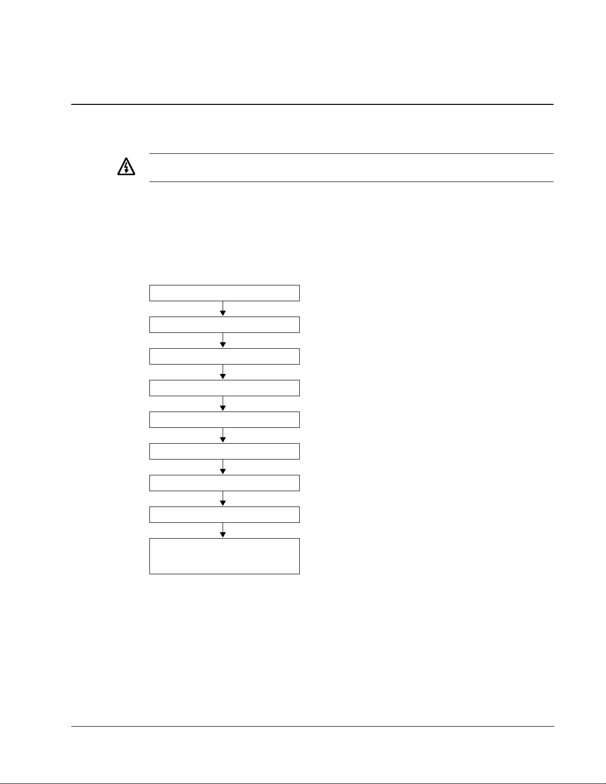
Installation Flow Chart . . . . . . . . . . . . . . . . . . . . . . . . . . . . . . . . . . . . . . . . . . . . 3
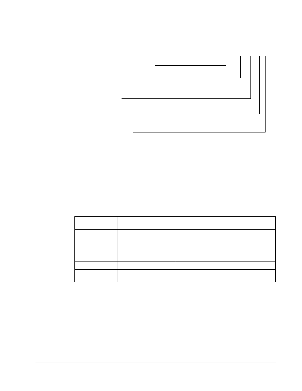
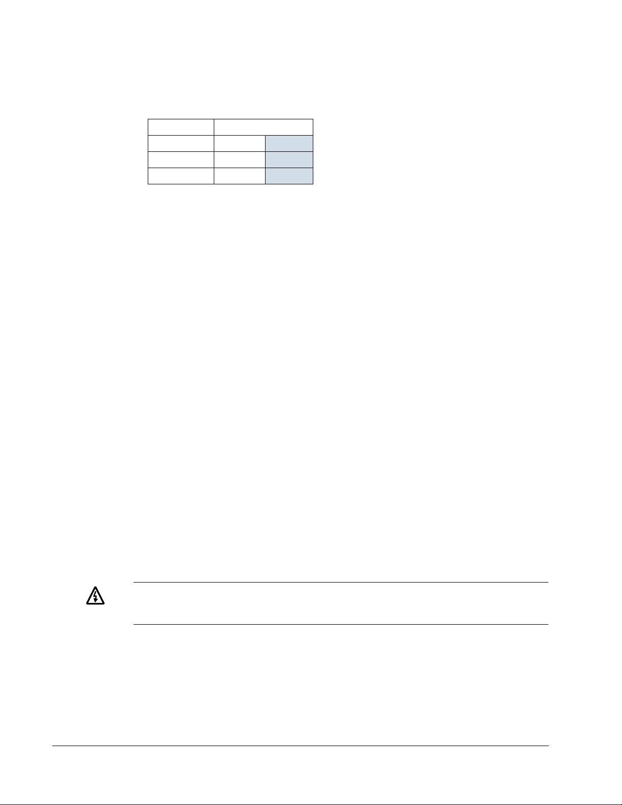
Preparing for Installation . . . . . . . . . . . . . . . . . . . . . . . . . . . . . . . . . . . . . . . . . . 4
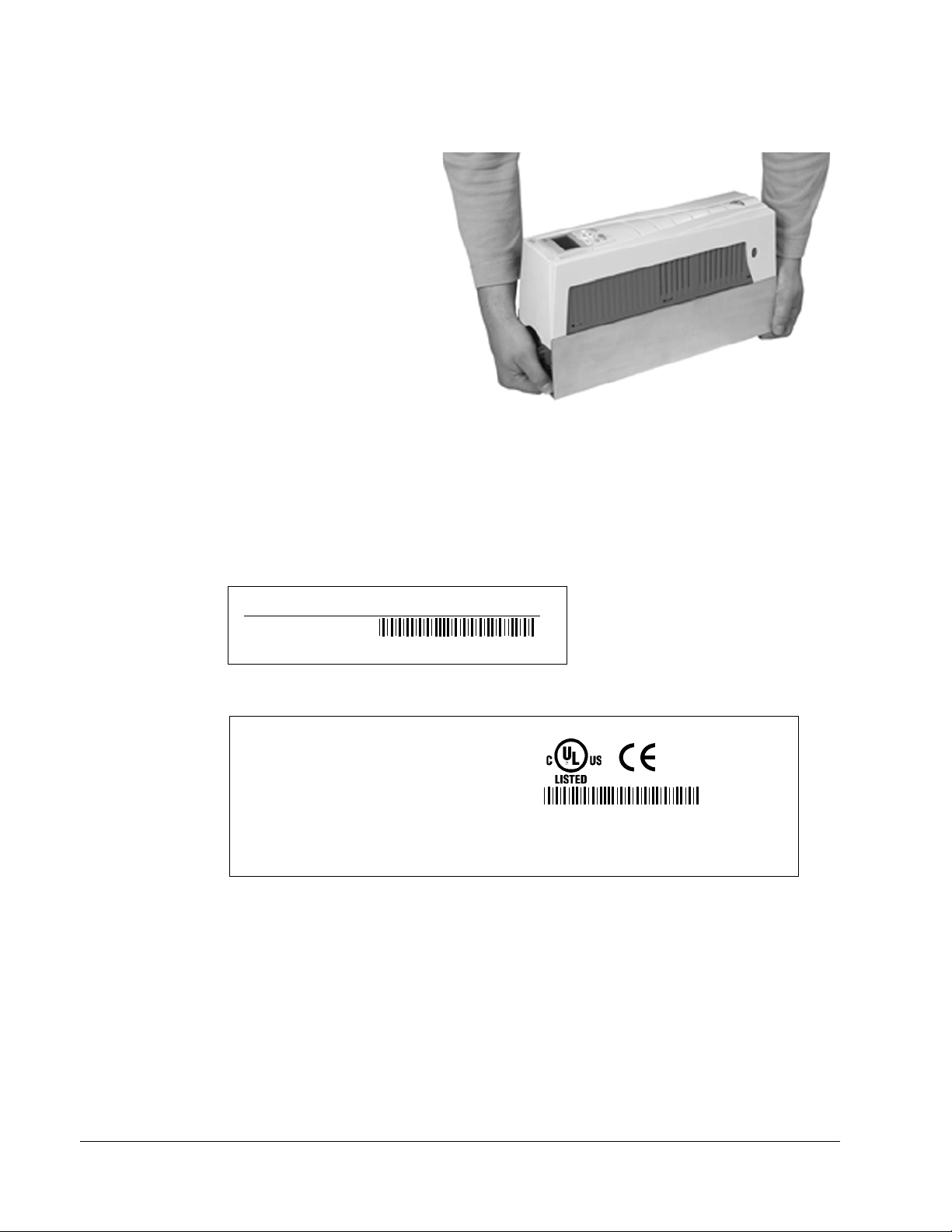
Installing the Drive . . . . . . . . . . . . . . . . . . . . . . . . . . . . . . . . . . . . . . . . . . . . . . . 6
Start-Up
HVAC Control Panel Features . . . . . . . . . . . . . . . . . . . . . . . . . . . . . . . . . . . . . 17
Start-Up . . . . . . . . . . . . . . . . . . . . . . . . . . . . . . . . . . . . . . . . . . . . . . . . . . . . . . 20
Modes . . . . . . . . . . . . . . . . . . . . . . . . . . . . . . . . . . . . . . . . . . . . . . . . . . . . . . . . 20
Application Macros . . . . . . . . . . . . . . . . . . . . . . . . . . . . . . . . . . . . . . . . . . . . . . 30
YORK Defaults . . . . . . . . . . . . . . . . . . . . . . . . . . . . . . . . . . . . . . . . . . . . . . . . . 46
Parameter Descriptions . . . . . . . . . . . . . . . . . . . . . . . . . . . . . . . . . . . . . . . . . . 48
Serial Communication – EFB
Overview . . . . . . . . . . . . . . . . . . . . . . . . . . . . . . . . . . . . . . . . . . . . . . . . . . . . 140
Planning . . . . . . . . . . . . . . . . . . . . . . . . . . . . . . . . . . . . . . . . . . . . . . . . . . . . . 141
Mechanical and Electrical Installation – EFB . . . . . . . . . . . . . . . . . . . . . . . . . 142
Communication Set-up – EFB . . . . . . . . . . . . . . . . . . . . . . . . . . . . . . . . . . . . 143
Activate Drive Control Functions – EFB . . . . . . . . . . . . . . . . . . . . . . . . . . . . . 144
Feedback from the Drive – EFB . . . . . . . . . . . . . . . . . . . . . . . . . . . . . . . . . . . 148
Diagnostics – EFB . . . . . . . . . . . . . . . . . . . . . . . . . . . . . . . . . . . . . . . . . . . . . 150
Modbus Protocol Technical Data . . . . . . . . . . . . . . . . . . . . . . . . . . . . . . . . . . 152
YORK Drives Profile Technical Data . . . . . . . . . . . . . . . . . . . . . . . . . . . . . . . 159
N2 Protocol Technical Data . . . . . . . . . . . . . . . . . . . . . . . . . . . . . . . . . . . . . . 167
FLN Protocol Technical Data . . . . . . . . . . . . . . . . . . . . . . . . . . . . . . . . . . . . . 176
BACnet Technical Data . . . . . . . . . . . . . . . . . . . . . . . . . . . . . . . . . . . . . . . . . 189
Serial Communication – FBA
Overview . . . . . . . . . . . . . . . . . . . . . . . . . . . . . . . . . . . . . . . . . . . . . . . . . . . . 190
Planning . . . . . . . . . . . . . . . . . . . . . . . . . . . . . . . . . . . . . . . . . . . . . . . . . . . . . 192
Mechanical and Electrical Installation – FBA . . . . . . . . . . . . . . . . . . . . . . . . . 193
Communication Set-up – FBA . . . . . . . . . . . . . . . . . . . . . . . . . . . . . . . . . . . . 194
Activate Drive Control Functions – FBA . . . . . . . . . . . . . . . . . . . . . . . . . . . . . 194
Feedback from the Drive – FBA . . . . . . . . . . . . . . . . . . . . . . . . . . . . . . . . . . . 197
Diagnostics – FBA . . . . . . . . . . . . . . . . . . . . . . . . . . . . . . . . . . . . . . . . . . . . . 198
YORK Drives Profile Technical Data . . . . . . . . . . . . . . . . . . . . . . . . . . . . . . . 199
Generic Profile Technical Data . . . . . . . . . . . . . . . . . . . . . . . . . . . . . . . . . . . . 207
Diagnostics
Diagnostic Displays . . . . . . . . . . . . . . . . . . . . . . . . . . . . . . . . . . . . . . . . . . . . 209
Correcting Faults . . . . . . . . . . . . . . . . . . . . . . . . . . . . . . . . . . . . . . . . . . . . . . 210
Correcting Alarms . . . . . . . . . . . . . . . . . . . . . . . . . . . . . . . . . . . . . . . . . . . . . . 215

AYK550-UH User’s Manual
Table of Contents
Maintenance
Maintenance Intervals . . . . . . . . . . . . . . . . . . . . . . . . . . . . . . . . . . . . . . . . . . 218
Heatsink . . . . . . . . . . . . . . . . . . . . . . . . . . . . . . . . . . . . . . . . . . . . . . . . . . . . 218
Main Fan Replacement . . . . . . . . . . . . . . . . . . . . . . . . . . . . . . . . . . . . . . . . . 219
Capacitors . . . . . . . . . . . . . . . . . . . . . . . . . . . . . . . . . . . . . . . . . . . . . . . . . . . 220
Control Panel . . . . . . . . . . . . . . . . . . . . . . . . . . . . . . . . . . . . . . . . . . . . . . . . . 220
Technical Data
Ratings . . . . . . . . . . . . . . . . . . . . . . . . . . . . . . . . . . . . . . . . . . . . . . . . . . . . . 221
Input Power Connections . . . . . . . . . . . . . . . . . . . . . . . . . . . . . . . . . . . . . . . 224
Motor Connections . . . . . . . . . . . . . . . . . . . . . . . . . . . . . . . . . . . . . . . . . . . . 228
Control Connections . . . . . . . . . . . . . . . . . . . . . . . . . . . . . . . . . . . . . . . . . . . 233
Efficiency . . . . . . . . . . . . . . . . . . . . . . . . . . . . . . . . . . . . . . . . . . . . . . . . . . . . 236
Cooling . . . . . . . . . . . . . . . . . . . . . . . . . . . . . . . . . . . . . . . . . . . . . . . . . . . . . 236
Dimensions and Weights . . . . . . . . . . . . . . . . . . . . . . . . . . . . . . . . . . . . . . . . 237
Degrees of Protection . . . . . . . . . . . . . . . . . . . . . . . . . . . . . . . . . . . . . . . . . . 240
Ambient Conditions . . . . . . . . . . . . . . . . . . . . . . . . . . . . . . . . . . . . . . . . . . . . 240
Materials . . . . . . . . . . . . . . . . . . . . . . . . . . . . . . . . . . . . . . . . . . . . . . . . . . . . 240
Applicable Standards . . . . . . . . . . . . . . . . . . . . . . . . . . . . . . . . . . . . . . . . . . 240
Liability Limits . . . . . . . . . . . . . . . . . . . . . . . . . . . . . . . . . . . . . . . . . . . . . . . . 243
Appendix A
Factory-Mounted Solution and AirPak AHU VFDs . . . . . . . . . . . . . . . . . . . . . . .A1
Configurations . . . . . . . . . . . . . . . . . . . . . . . . . . . . . . . . . . . . . . . . . . . . . . . . . .A2
Mechanical Dimensions . . . . . . . . . . . . . . . . . . . . . . . . . . . . . . . . . . . . . . . . . . .A2
Appendix B
Field-Mounted Ship Loose Air Mods . . . . . . . . . . . . . . . . . . . . . . . . . . . . . . . . .B1
Configurations . . . . . . . . . . . . . . . . . . . . . . . . . . . . . . . . . . . . . . . . . . . . . . . . . .B1
Mechanical Dimensions . . . . . . . . . . . . . . . . . . . . . . . . . . . . . . . . . . . . . . . . . . .B1
Appendix C
Quick Start-Up Guide . . . . . . . . . . . . . . . . . . . . . . . . . . . . . . . . . . . . . . . . . . . . .C1
Analog Input Configuration. . . . . . . . . . . . . . . . . . . . . . . . . . . . . . . . . . . . . . . . .C2
RS485 Interface Termination for Serial Communication . . . . . . . . . . . . . . . . . .C2
Customer Control Terminal Interface . . . . . . . . . . . . . . . . . . . . . . . . . . . . . . . . .C2
Typical Motor Nameplate . . . . . . . . . . . . . . . . . . . . . . . . . . . . . . . . . . . . . . . . . .C3
IGBT Test Method . . . . . . . . . . . . . . . . . . . . . . . . . . . . . . . . . . . . . . . . . . . . . . .C4
Inverter Component Values . . . . . . . . . . . . . . . . . . . . . . . . . . . . . . . . . . . . . . . .C4
Inverter Diodes and IGBT Components . . . . . . . . . . . . . . . . . . . . . . . . . . . . . . .C4

AYK550-UH User’s Manual
Table of Contents
Appendix D
Solution AHU Drawing #205662 . . . . . . . . . . . . . . . . . . . . . . . . . . . . . . . . . . . . D1
#205648 . . . . . . . . . . . . . . . . . . . . . . . . . . . . . . . . . . . . D2
#205647 . . . . . . . . . . . . . . . . . . . . . . . . . . . . . . . . . . . . D3
#205651 . . . . . . . . . . . . . . . . . . . . . . . . . . . . . . . . . . . . D4
#205649 . . . . . . . . . . . . . . . . . . . . . . . . . . . . . . . . . . . . D5
#205653 . . . . . . . . . . . . . . . . . . . . . . . . . . . . . . . . . . . . D6
#205663 . . . . . . . . . . . . . . . . . . . . . . . . . . . . . . . . . . . . D7
#205652 . . . . . . . . . . . . . . . . . . . . . . . . . . . . . . . . . . . . D8
#205650 . . . . . . . . . . . . . . . . . . . . . . . . . . . . . . . . . . . . D9
#205654 . . . . . . . . . . . . . . . . . . . . . . . . . . . . . . . . . . . D10
#205633 . . . . . . . . . . . . . . . . . . . . . . . . . . . . . . . . . . . D11
AirPak AHU Drawing #205662 . . . . . . . . . . . . . . . . . . . . . . . . . . . . . . . . . . . . D1
#205648 . . . . . . . . . . . . . . . . . . . . . . . . . . . . . . . . . . . . D2
#205651 . . . . . . . . . . . . . . . . . . . . . . . . . . . . . . . . . . . . D4
#205652 . . . . . . . . . . . . . . . . . . . . . . . . . . . . . . . . . . . . D8
Appendix E
Solution & AirPak Dimensions
AYK550 Frame Size Chart . . . . . . . . . . . . . . . . . . . . . . . . . . . . . . . . . . . . . . E1
Base Drive (OO Option) Outside Dimensions . . . . . . . . . . . . . . . . . . . . . . . E2
Weights . . . . . . . . . . . . . . . . . . . . . . . . . . . . . . . . . . . . . . . . . . . . . . . . . . . . E2
Base Drive w/Fused Disconnects (AO Option) Dimensions & Weights . . . . E3
Field Mounted Shipped Loose AirMods
Base Drive, 2 Contactor, Drive Input Service Disconnect Switch,
Main Fused Disconnect Switch (CM Option) Enclosure
Drawings & Dimensions . . . . . . . . . . . . . . . . . . . . . . . . . . . . . . . . . . . . . . E4
Mounting Dimensions . . . . . . . . . . . . . . . . . . . . . . . . . . . . . . . . . . . . . . . . . . E5
Outside Dimensions . . . . . . . . . . . . . . . . . . . . . . . . . . . . . . . . . . . . . . . . . . . E6
Wire Sizes . . . . . . . . . . . . . . . . . . . . . . . . . . . . . . . . . . . . . . . . . . . . . . . . . . . . . E7
Index

1AYK550-UH User’s Manual
Safety
Safety
Warning! The AYK550 adjustable speed AC drive should ONLY be installed by
a qualified electrician.
Warning! Even when the motor is stopped, dangerous voltage is present at the
Power Circuit terminals U1, V1, W1 and U2, V2, W2 and, where present, UDC+,
UDC-, BRK+ and BRK-.
Warning! Dangerous voltage is present when input power is connected. After
disconnecting the supply, wait at least 5 minutes (to let the intermediate circuit
capacitors discharge) before removing the cover.
Warning! Even when power is removed from the input terminals of the
AYK550, there may be dangerous voltage (from external sources) on the
terminals of the relay outputs R01…R03.
Warning! When the control terminals of two or more drive units are connected
in parallel, the auxiliary voltage for these control connections must be taken
from a single source which can either be one of the units or an external
supply.
Warning! The AYK550-UH is not a field repairable unit. Never attempt to repair
a malfunctioning unit; contact the factory or your local Authorized Service
Center for replacement.
Warning! The AYK550 will start up automatically after an input voltage
interruption if the external run command is on.
Warning! The heat sink may reach a high temperature. See "Technical Data" on
page 225.
Warning! If the drive will be used in a floating network, remove screws at EM1
and EM3 (Frame size R1…R4), or F1 and F2 (Frame size R5 or R6). See
diagrams on page 12 and page 13 respectively.
Note! For more technical information, contact the factory or your local YORK sales
representative.

AYK550-UH User’s Manual 2
Safety
Use of Warnings and Notes
There are two types of safety instructions throughout this manual:
• Notes draw attention to a particular condition or fact, or give information on a
subject.
• Warnings caution you about conditions which can result in serious injury or death
and/or damage to the equipment. They also tell you how to avoid the danger. The
warning symbols are used as follows:
Dangerous voltage warning warns of high voltage which can cause physical
injury and/or damage to the equipment.
General warning warns about conditions, other than those caused by
electricity, which can result in physical injury and/or damage to the equipment

AYK550-UH User’s Manual 3
Installation
Installation
Study these installation instructions carefully before proceeding. Failure to observe
the warnings and instructions may cause a malfunction or personal hazard.
Warning! Before you begin read "Safety" on page 1.
Installation Flow Chart
The installation of the AYK550 adjustable speed AC drive follows the outline below.
The steps must be carried out in the order shown. At the right of each step are
references to the detailed information needed for the correct installation of the unit.
Task See
PREPARE for installation "Preparing for Installation" on page 4.
PREPARE the Mounting Location "Prepare the Mounting Location" on page 9.
REMOVE the front cover "Remove Front Cover" on page 7.
MOUNT the drive "Mount the Drive" on page 8.
INSTALL wiring "Install the Wiring" on page 8.
CHECK installation "Check Installation" on page 13.
RE-INSTALL the cover "Re-install Cover" on page 13.
APPLY power "Apply Power" on page 17.
START-UP "Note! For drives with bypass, if motor is running in
reverse switch incoming power lines at input disconnect."
on page 14.

4AYK550-UH User’s Manual
Installation
Preparing for Installation
Lifting the Drive
Lift the drive only by the metal
chassis.
Unpack the Drive
1. Unpack the drive.
2. Check for any damage and
notify the shipper immediately
if damaged components are
found.
3. Check the contents against
the order and the shipping label to verify that all parts have been received.
Drive Identification
Drive Labels
To determine the type of drive you are installing, refer to either:
• Serial number label attached on upper part of the chokeplate between the
mounting holes.
• Type code label attached on the heat sink – on the right side of the unit cover.
IP2040
Ser. no.
AYK550-UH-08A8-4
*2030700001*
U1
I2N
PN
8.8 A
4
3~ 380...480 V
Ser. no.
AYK550-UH-08A8-4
*2030700001*
Input U1
I1N
f1
Output U2
I2N
f2
Motor PN
48...63 Hz
8.8 A
3~ 380...480 V
3~ 0...U1V
8.8 A
0...500 Hz
4

AYK550-UH User’s Manual 5
Installation
Type Code
Use the following chart to interpret the type code found on either label.
Ratings and Frame Size
The chart in "Ratings" on page 225 lists technical specifications, and identifies the
drive’s frame size – significant, since some instructions in this document, vary,
depending on the drive’s frame size. To read the Ratings table, you need the “Output
current rating” entry from the type code (see above). Also, when using the Ratings
tables, note that there are two tables based on the drive’s “Voltage rating”.
Motor Compatibility
The motor, drive, and supply power must be compatible:
Tools Required
To install the AYK550 you need the following:
• Screwdrivers (as appropriate for the mounting hardware used)
• Wire stripper
• Tape measure
•Drill
Motor
Specification Verify Reference
Motor type 3-phase induction motor –
Nominal current Motor value is within this
range: 0.15…1.5 * I2N
(I2N = normal use current)
• Type code label on drive, entry for Output I2N,
or
• Type code on drive and rating table in
"Technical Data" on page 225.
Nominal frequency 10…500 Hz –
Voltage range Motor is compatible with
the AYK550 voltage range.
208…240 V (for AYK550-UH-XXXX-2) or
380…480 V (for AYK550-UH-XXXX-4)
AYK550-UH-08A8-4+...
AC, HVAC Drive – 550 product series
See Ratings chart for details
4 = 380…480 VAC
UH = Setup and parts specific to US installation and NEMA compliance
2 = 208…240 VAC
Construction (region specific)
Output current rating
Voltage rating
01 = Setup and parts specific to IEC installation and compliance
Enclosure protection class
No specification = IP 21 / UL type 1

6AYK550-UH User’s Manual
Installation
• Frame Size R5 or R6: Punch for conduit mounting holes
• Mounting hardware: screws or nuts and bolts, four each. The type of hardware
depends on the mounting surface and the frame size:
Suitable Environment and Enclosure
Confirm that the site meets the environmental requirements. To prevent damage
prior to installation, store and transport the drive according to the environmental
requirements specified for storage and transportation. See "Ambient Conditions" on
page 244.
Confirm that the enclosure is appropriate, based on the site contamination level:
• IP 21 / UL type 1 enclosure. The site must be free of airborne dust, corrosive
gases or liquids, and conductive contaminants such as condensation, carbon
dust, and metallic particles.
Suitable Mounting Location
Confirm that the mounting location meets the following constraints:
• The drive must be mounted vertically on a smooth, solid surface, and in a suitable
environment as defined above.
• The minimum space requirements for the drive are the outside dimensions (see
"Outside Dimensions" on page 243), plus air flow space around the unit (see
"Cooling" on page 240).
• The distance between the motor and the drive is limited by the maximum motor
cable length. See either "Motor Connection Specifications" on page 232, or
"EN61800-3 Compliant Motor Cables" on page 235.
• The mounting site must support the drive’s modest weight. See "Weight" on page
242.
Installing the Drive
Warning! Before installing the AYK550, ensure the input power supply to the
drive is off.
Frame Size Mounting Hardware
R1…R4 M5 #10
R5 M6 1/4 in
R6 M8 5/16 in

AYK550-UH User’s Manual 7
Installation
Prepare the Mounting Location
The AYK550 should only be mounted where all of the
requirements defined in "Preparing for Installation" on
page 4 are met.
1. Mark the position of the mounting holes.
2. Drill holes of appropriate size.
Note! Frame sizes R3 and R4 have four holes along the top. Use only two. If
possible, use the two outside holes (to allow room to remove the fan for
maintenance).
Note! AYK400 drives can be replaced using the original mounting holes. For R1 and
R2 frame sizes, the mounting holes are identical. For R3 and R4 frame sizes, the
inside mounting holes on the top of AYK550 drives match AYK400 mounts.
Remove Front Cover
IP 21 / UL Type 1
1. Remove the control panel, if attached.
2. Loosen the captive screw at the top.
3. Pull near the top to remove the cover.
X0002
1
3
IP2000
1
2

8AYK550-UH User’s Manual
Installation
Mount the Drive
IP 21 / UL Type 1
1. Position the AYK550 onto the mounting screws
or bolts and securely tighten in all four corners.
Note! Lift the AYK550 by its metal chassis.
2. Non-English speaking locations: Add a warning
sticker in the appropriate language over the
existing warning on the top of the module.
Install the Wiring
Conduit Kit
Wiring drives with the IP 21 / UL type 1 Enclosure requires a conduit kit with the
following items:
• conduit box
•screws
• cover
The kit is included with IP 21 / UL type 1 Enclosures.
IP2002
1
2

AYK550-UH User’s Manual 9
Installation
Wiring Overview
Warning! Ensure the motor is compatible for use with the AYK550. The AYK550
must be installed by a competent person in accordance with the
considerations defined in "Preparing for Installation" on page 4. If in doubt,
contact your local YORK sales or service office.
As you install the wiring, observe the following:
• For the power connection points on the drive see the "Connection Diagrams"
section below.
• Use separate conduit runs to keep these three classes of wiring apart:
– Input power wiring.
– Motor wiring.
– Control/communications wiring.
• For details on power connections, refer to the following sections in "Technical
Data":
– "Input Power Connections" on page 228.
– "Motor Connections" on page 232.
• For floating networks (also known as IT, ungrounded, or high impedance
networks):
– Disconnect the internal RFI filter by removing both the EM1 and EM3 screws
(frame sizes R1…R4, see page 10), or F1 and F2 screws (frame sizes
R5…R6, see page 11).
– Do NOT install an external filter, such as one of the kits listed in the filter table
on 236. Using an EMC/RFI filter grounds the input power through the filter
capacitors, which could be dangerous and could damage the unit.
– Where EMC requirements exist, check for excessive emission propagated to
neighboring low voltage networks. In some cases, the natural suppression in
transformers and cables is sufficient. If in doubt, use a supply transformer with
static screening between the primary and secondary windings.
• For details on control connections, refer to the following sections:
– "Control Connections" on page 237.
– "Application Macros" starting on page 35.
• For electro-magnetic compliance (EMC), follow local codes and the requirements
in "Motor Cable Requirements for CE & C-Tick Compliance" on page 234. For
example:
– Properly ground the wire screen cable shields.
– Keep individual un-screened wires between the cable clamps and the screw
terminals as short as possible.
– Route control cables away from power cables.

10 AYK550-UH User’s Manual
Installation
Connection Diagrams
The layout of connection terminals is similar for all frame sizes (R1…R6). The only
significant layout difference is in the power and ground terminals for frame sizes R5
and R6. The following diagrams show:
• Terminal layout for frame size R3, which, in general, applies to all frame sizes
except as noted above.
• Power and ground terminal layout for frame sizes R5 and R6.
Warning! For floating (ungrounded) networks remove screws at EM1 and EM3.
Panel Connector
Power LED (Green)
Fault LED (Red)
Optional Module 1
X1 – Communications
Optional Module 2
GND
Power Output to Motor
Power Input
EM1
J1 – DIP Switches
X1 – Analog Inputs and Outputs
X1 – Digital Inputs
X1 – Relay Outputs
for Analog Inputs
J1
AI1: (in Voltage Position)
AI2: (in Current Position)
ON
ON
(and 10 V Ref. Voltage Output)
(and 24 V Aux. Voltage Output)
EM3
PE
(U1, V1, W1) (U2, V2, W2)
X0003
(RS485)
R5/R6 differ.
See next page.
Frame Sizes
R1…R4 (Diagram shows the R3 frame.)
J2 – DIP Switches
J2
ON
off position on position
for RS485 Termination
J2
ON
Terminals Not Used

AYK550-UH User’s Manual 11
Installation
Warning! For floating (ungrounded) networks remove screws at F1 and F2.
GND
Power Input
PE
(U1, V1, W1)
X0011
F1
F2
Power Input
PE
(U1, V1, W1)
F1
F2
X0013
Power Output to Motor
(U2, V2, W2)
R5 R6
GND
GND
Power Output to Motor
(U2, V2, W2)
Terminals Not Used
Terminals Not Used

12 AYK550-UH User’s Manual
Installation
Wiring IP 21 / UL Type 1 Enclosure (Base Drive)
1. Open the appropriate knockouts in the
conduit box. (See "Conduit Kit" above.)
2. Install thin-wall conduit clamps (not supplied).
3. Install conduit box.
4. Connect conduit runs for input power, motor
and control cables to the box.
5. Route input power and motor wiring through
separate conduits.
6. Strip wires.
7. Connect power, motor, and ground wires to
the drive terminals. See "Wiring Overview" on
page 9.
8. Route the control cables through the conduit
(not the same conduit as either input power or
motor wiring).
9. Strip the control cable sheathing and twist the
copper screen into a pig-tail.
10. Connect the ground screen pig-tail for digital
and analog I/O cables at X1-1. (Ground only
at drive end.)
11. Connect the ground screen pig-tail for RS485
cables at X1-28 or X1-32. (Ground only at
drive end.)
12. Strip and connect the individual control wires
to the drive terminals. See "Wiring Overview"
on page 9.
13. Install the conduit box cover (1 screw).
2X0007
3
X0005
4IP2004
7
7
5
10
8
IP2005
12

AYK550-UH User’s Manual 13
Installation
Check Installation
Before applying power, perform the following checks.
Re-install Cover
IP 21 / UL Type 1
1. Align the cover and slide it on.
2. Tighten the captive screw.
3. Re-install the control panel.
Apply Power
Always re-install the front cover before turning
power on.
Warning! The AYK550 will start up
automatically at power up, if the external
run command is on.
1. Apply input power.
When power is applied to the AYK550, the green LED comes on.
Check
Installation environment conforms to the drive’s specifications for ambient conditions.
The drive is mounted securely.
Space around the drive meets the drive’s specifications for cooling.
The motor and driven equipment are ready for start.
For floating networks: The internal RFI filter is disconnected.
The drive is properly grounded.
The input power voltage matches the drive nominal input voltage range.
The input power connections at U1, V1, and W1 are connected and tightened as specified.
The input power branch circuit protection is installed.
The motor connections at U2, V2, and W2 are connected and tightened as specified.
The input power, motor and control wiring are routed through separate conduit runs.
NO power factor compensation capacitors are in the motor cable.
The control connections are connected and tightened as specified.
NO tools or foreign objects (such as drill shavings) are inside the drive.
NO alternate power source for the motor (such as a bypass connection) is connected – no
voltage is applied to the output of the drive.
3
1
2
IP2009

14 AYK550-UH User’s Manual
Installation
Note! Before increasing motor speed, check that the motor is running in the desired
direction.To change rotation direction, switch motor leads as shown below.
Note! For drives with bypass, if motor is running in reverse switch incoming power
lines at input disconnect.
Start-Up
The AYK550 has default parameter settings that are sufficient for many situations.
However, review the following situations. Perform the associated procedures as
appropriate.
Spin Motor
When first installed and started the control panel displays a welcome screen with the
following options.
• Press Exit to commission the drive as described in section “Start-Up by Changing
the Parameters Individually” on page 23.
• Press Enter to move to the following options:
– Select “Commission Drive” to commission the drive as described in section
“Start-Up by Using the Start-Up Assistant” on page 23.
– Select “Spin Motor” to operate the motor prior to commissioning. This option
operates the motor without any commissioning, except entry of the motor data
as described below. Spin Motor is useful, for example, to operate ventilation
fans prior to commissioning.
Note! When using Spin Motor, the motor speed is limited to the range 1/3…2/3 of
maximum speed. Also, no interlocks are activated. Finally, once the drive is
commissioned, the welcome screen and this option no longer appear.
U1 V1 W1 U2 V2 W2
L1
L2
L3
Motor
Drive
Input
FM
U1 V1 W1 U2 V2 W2
L1
L2
L3
Motor
Drive
Input
To change rotation direction,
switch motor leads
GND
GND
GND
GND

AYK550-UH User’s Manual 15
Installation
Motor Data
The motor data on the ratings plate may differ from the defaults in the AYK550. The
drive provides more precise control and better thermal protection if you enter the
rating plate data.
1. Gather the following from the motor ratings plate:
•Voltage
• Nominal motor current
• Nominal frequency
• Nominal speed
• Nominal power
2. Edit parameters 9905…9909 to the correct values.
• Assistant Control Panel: The Start-up Assistant walks you through this data entry
(see page 27).
• Basic Control Panel: Refer to "Parameters Mode" on page 26, for parameter
editing instructions.
Macros
Note! Selecting the appropriate macro should be part of the original system design,
since the control wiring installed depends on the macro used.
1. Review the macro descriptions in "Application Macros" on page 35. Use the macro
that best fits system needs.
2. Edit parameter 9902 to select the appropriate macro. Use either of the following:
• Use the Start-up Assistant, which displays the macro selection immediately after
motor parameter setup.
• Refer to "Parameters Mode" on page 26, for parameter editing instructions.
Tuning – Parameters
The system can benefit from one or more of the AYK550 special features, and/or fine
tuning.
1. Review the parameter descriptions in "Parameter Descriptions" starting on page 51.
Enable options and fine tune parameter values as appropriate for the system.
2. Edit parameters as appropriate.
Fault and Alarm Adjustments
The AYK550 can detect a wide variety of potential system problems. For example,
initial system operation may generate faults or alarms that indicate set-up problems.
1. Faults and alarms are reported on the control panel with a number. Note the number
reported.
2. Review the description provided for the reported fault/alarm:

16 AYK550-UH User’s Manual
Installation
• Use the fault and alarm listings on pages 213 and 218 respectively, or
• Press the help key (Assistant Control Panel only) while fault or alarm is displayed.
3. Adjust the system or parameters as appropriate.
Other manuals for AYK 550
1
Table of contents
Other York Modulator manuals