York 2ET04700224 User manual

USER GUIDE
Programmable Thermostat - 2ET04700224 / 324 / 424
Roof - Top units
THERMOSTATS

2
Table of Contents
Page
1- Specifications
......................................................................................................................................................................
3
1.1 - Product range
.................................................................................................................................................................................................
3
•
2ET04700224
...........................................................................................................................................................................................
3
•
2ET04700324
...........................................................................................................................................................................................
3
•
2ET04700424
...........................................................................................................................................................................................
3
1.2 - General features
...........................................................................................................................................................................................
3
1.3 - Dimensions
......................................................................................................................................................................................................
3
1.4 - Recovery from unoccupied mode
.....................................................................................................................................................
3
2- Installation
.............................................................................................................................................................................
4
2.1 - New installation
.............................................................................................................................................................................................
4
2.2 - Mount subbase or wallplate
..................................................................................................................................................................
4
2.3 - Set subbase dip switches
.......................................................................................................................................................................
4
2.4 - Set thermostat mini-jumper
.................................................................................................................................................................
4
2.5 - Set display dip switches
..........................................................................................................................................................................
4
2.6 - Mount thermostat
.........................................................................................................................................................................................
5
2.7 - Install battery
..................................................................................................................................................................................................
5
3- Wiring
......................................................................................................................................................................................
6
3.1 - Connections between thermostat and equipment terminals - 2ET04700224
......................................................
6
3.2 - Connections between thermostat and equipment terminals - 2ET04700324
......................................................
6
3.3 - Connections between thermostat and equipment terminals - 2ET04700424
......................................................
6
4- Programming the thermostat
4.1 - Overview
............................................................................................................................................................................................................
7
4.2 - Set current time / day
................................................................................................................................................................................
7
4.3 - Set program times
.......................................................................................................................................................................................
7
4.4- Copy a day
........................................................................................................................................................................................................
7
4.5 - Set program temperature setpoints
.................................................................................................................................................
7
4.6 - Set operating display
.................................................................................................................................................................................
7
4.7 - Clear start time
..............................................................................................................................................................................................
7
4.8 - Temporarily override program
.............................................................................................................................................................
8
- 3 hour occupied
............................................................................................................................................................................................
8
- 3 hour occupied with + or - Key
.........................................................................................................................................................
9
- Set 3 hour occupied Override With + or - Key
.........................................................................................................................
9
4.9 - Cont Unoc
.........................................................................................................................................................................................................
9

3
1.1 - Product range
2ET04700224
This thermostat may be used with the following units:
- All DCE (with or without electrical heaters) and DIG roof top
units.
2ET04700324
This thermostat may be used with the following units :
- BCH 036 / 060 (with or without electrical heaters).
2ET04700424
This thermostat may be used with the following units :
- BCH 090 / 120 and BIH 180 / 240 (with or without electrical
heaters).
Technical data
1.2 - General features
• One model can be used for single-stage and multistage appli-
cations.
• Day programming : two occupied/unoccupied periods per day.
• Individual temperature setpoints for:
- Occupied heat and cool.
- Unoccupied heat and cool.
• Proportional plus integral control eliminates temperature fluc-
tuations and thermostat tampering.
• Intelligent Recovery : automatically optimises start time depen-
ding on building load.
• Intelligent Fan energizes fan on call for heating or cooling only.
Fan can be configured to run continuously in occupied mode.
• Automatic heat/cool changeover.
• Locking setpoints and schedules eliminate tampering (user
keyboard security).
• One thermostat can be used for heat pump or conventional
control.
• Optional remote sensors.
• Convenient overrides allow temporary changes.
1.3 - Dimensions
1.4 - Recovery from unoccupied
Intelligent RecoveryTM is a Honeywell trademark for the way the
thermostat controls the heating and cooling equipment during
recovery from unoccupied to occupied setting. During recovery,
the control point ramps up at the rate of 3°C per hour rather than
jumping from the energy savings setting to the comfort setting all
at once. This provides additional energy savings.
When the Intelligent RecoveryTM is used in the heating mode the
control point raises 3°C per hour (2°C for the heat pump), maxi-
mizing the use of the more economical first stage heat to bring
the sensed temperature to the desired comfort setpoint. This
minimizes using the typically more expensive second stage heat.
The advantages are:
- Comfort setting is achieved at the programmed time and main-
tained regardless of weather conditions; occupants are com-
fortable.
- Drafts from low temperature discharge air are minimized during
occupied periods.
- The thermostat automatically uses the more economical first
stage of heat as the primary heat source during heat mode
recovery, avoiding the use of the expensive second stage
heating.
- Comfort and energy savings can be achieved in both heating
and cooling.
- The thermostat reduces heat cycling, extending equipment life.
1 - Specifications
3
Description Values
Rated Voltage 24-30 Vac, 50/60 Hz
Rated A.C Current 1,6 Amps continuous per output
with surges to 3,5 Amp Max.
Control Range 7 to 35°C; 1°C Steps
Thermostat
Measurement range 4 to 43°C
Control Accuracy ±0,5°C at 20°C
Minimum deadband Between heating and cooling : 1°C
Clock accuracy +/- 1 minute per month
Default setpoint 20°C during occupied period
heating 13°C during unoccupied period
Default setpoint 26°C during occupied period
cooling 32°C during unoccupied period
Anti recycle time 2 min ON / 4 min OFF
Battery backup Up to 60 hours with fresh 9 Volts
alkaline battery
FAN AUTO ON EM HEAT HEAT OFF COOL
EM HEAT AUX HEAT
204
102 118
41

4
2.1 - New Installation
Run cable to a hole at the selected wall location for the thermo-
stat and pull about 75 mm of wire through the opening. Color-
coded thermostat cable with at least one conductor for each
wiring terminal is recommended. Good service practice recom-
mends selecting a cable with one or two extra conductors than
the immediate application requires.
If using remote temperature sensor(s), refer to the mounting ins-
tructions included with the device for wiring cable requirements.
Route cable away from sources of electrical interference.
2.2 - Mount subbase or wallplate
The subbase or wallplate can be mounted on a horizontal outlet
box or directly on the wall.
For a wall installation, hold subbase or wallplate in position and
mark holes for the screws. See figure 1. Screws and wall plugs
must be obtained locally. Be careful that the wires do not fall
back into the wall opening. Set aside subbase or wallplate.
2.3 - Set subbase DIP switches
The Subbase provides the Thermostat with an interface to the
single zone HVAC system. See Table 1 for DIP switch settings.
The subbase DIP switches are located on the front and to the
right of the wiring terminals. See Fig.2. Set the DIP switches for
the system being controlled.
Table 1 - Subbase DIP switch settings
a. No effect on 2 heat/1 cool Thermostats/ 2ET04700324.
b. Factory setting.
c. No effect on heat pump subbases : 2ET04700324/424.
2.4 - Set thermostat mini-jumper
Note : This operation must be done prior to installing the
batteries. If batteries are installed prior to this operation,
remove battery for 15 minutes and begin.
The thermostat is factory-set for conventional system control. If
using with a heat pump 2ET04700324 or 424, locate the mini-
jumper on the back of the display. See Fig. 3. Pull the mini-jum-
per off the two CONV pins and move to the two HEAT PUMP
pins. This changes the thermostat to the heat pump algorithm.
If you wish to change the control of the thermostat because a
new subbase has been purchased, remove battery for 15
minutes, change mini-jumper position, and re-install battery.
2.5 - Set display DIP switches
The thermostat DIP switches provide the thermostat with an
interface to the single zone HVAC system. See Table 2 for DIP
switch settings. The display DIP switches are located on the
back of the thermostat. See Fig. 4. Set the DIP switches for the
desired thermostat features and the system being controlled.
CA1 CA2 CA3 CA4 CA5
LED1 LED2 COM
Y1 G RC RH
BA3A2A1W2Y2TT
Switch Setting Function
1aONb2 stages heat
OFF 1 stage heat
2aONb2 stages cool
OFF 1 stage cool
ONbProportional plus integral (P+I)
3 control (droopless)
OFF Proportional control (allows droop)
4cONbEnergizes fan on cool only
OFF Energizes fan on heat and cool
5ONbUse internal sensor
OFF Use remote sensor
2 - Installation
CA1 CA2 CA3 CA4 CA5
LED1 LED2 COM
Y1 G RC RH
BA3A2A1W2Y2TT
0
N
1234 5
4
1
T7300 ONLY
HEAT PUMP CONV
0N
12345
°C
24
CON
OFF
°F - TEMP
12 HR. TIME
INT - FAN
ON - KEYBD
0N
°F - TEMP
12 HR. TIME
INT - FAN
ON - KEYBD
12
T7300 ONLY
HEAT PUMP CONV
0N
12345
°C
24
CON
OFF
°F - TEMP
12 HR. TIME
INT - FAN
ON - KEYBD
0N
12345
°C
24
CON
OFF
°F -TEMP
12 HR. TIME
INT - FAN
ON - KEYBD
Fig. 1
Fig. 2 - Subbase DIP switches
Fig. 3 - Setting thermostat mini-jumper
Fig. 4 - Display DIP switches

5
2 - Installation (cont’d)
Table 2 - Display DIP switch settings
a : Factory settings.
2.6 - Mount thermostat
Caution
Always disconnect power supply and remove battery from the
thermostat before connecting the ribbon cables to prevent elec-
trical shock and equipment damage.
Use the Following procedure to connect the display ribbon
cables to the subbase.
1.
Check that the 24 Vac power supply is disconnected.
2.
Check that the 9 Vdc battery is not installed in the display.
Important :
First be sure to connect the 12 pin ribbon cable to
the base.
3.
Connect the 12 pin (larger) ribbon cable to the display. See
Fig. 4.
4.
Connect the 9 pin (smaller) ribbon cable to the display.
5.
If using a 9 Vdc battery, go to the Install Battery backup sec-
tion for installation instructions.
2.7 - Install battery
The 9 volts battery is not necessary for the operation of the ther-
mostat, but holds the program during power outages. When the
power is restored, the system will resume normal operation.
Without the battery, the system will adopt the default setpoints.
Refer to the "technical data". Use the following steps to install a
battery :
1.
Locate the battery holder on the back of the display.
2.
Slide the battery up to the connector until it is firmly seated.
Notes :
Observe the polarity when snapping a 9 volt alkaline bat-
tery into the holder.
The plugs must be firmly seated on the connectors for
the thermostat to work properly
3.
Hang the top edge of the display on the subbase hooks. See
Fig. 5.
4.
Swing down and press on the lower edge until the thermostat
snaps in place.
5.
Insert and tighten three Allen head screws on the bottom of
the thermostat. See Fig. 5.
Switch Setting Function
1ONa°F display
OFF °C display
2ONa12 hour clock display
OFF 24 hour clock display
ONaContinuous fan operation in occupied
3period
OFF Intermittent fan operation in occupied
period
4 Non functional switch
ONaKeyboard is used for programming
5OFF Keyboard disabled, but can be used
to review program, perform overrides
and make clock changes.
1
Fig. 5 - Ribbon cable and display monting

6
3 - Wiring
3.1 - Connections between thermostat and equip-
ment terminals - 2ET04700224
Note :
Use copper conductors only. Section > 1mm2.
1.
Electronic programmable thermostat 2ET04700224
(includes subbase).
2.
Terminals Al and A2 provide a relay output when the ther-
mostat switches to the set-back position.
3.
Terminal strip TB1 - locate on relay board in 24-volt section
of the unit control box.
3.2 - Connections between thermostat and equipment
terminals - 2ET04700324
1.
Electronic programmable thermostat 2ET04700324 with sub-
base for both manual and automatic changeover.
2.
Only required on units with economizer. Remove jumper J2
from terminals 4 and 9 on jumper plug P7. The outdoor air
intake dampers will return to their fully closed position when
the thermostat switches to the "unoccupied" mode.
3.
Second stage cooling is only required on units with economi-
zer. Remove jumper J1 from terminals 8 and 10 on jumper
plug connector P7.
4.
Only required on units with supplemental electric heat.
3.3 - Connections between thermostat and equipment
terminals - 2ET04700424
Note :
Use copper conductors only. Section > 1mm2.
1.
Electronic programmable thermostat 2ET04700424
(includes subbase).
2.
Second stage heating only required on units with supple-
mental resistance heat.
3.
Terminals A1 and A2 provide a relay output when the ther-
mostat switches to the setback position.
2
2
RH
RC
Y1
Y2
W1
W2
G
B
LED 1
LED 2
COM
A1
A2
T
T
R
Y1
Y2
W1
W2
G
B
X
A1
A2
24V
transformer
Unit terminal strip TB1
3
Thermostat1terminals
Add jumper
Add jumper
Not used
To remote sensor 2TH04702224 if used
Y2
W1
G
B
O
Y1
X
Y2
W1
G
B
O
Y1
X
R
N
A1
R
A2
COM
LED 1
LED 2
T
T
2
3
4
24V
transformer
Unit terminal strip TB1
Thermostat1terminals
Add
jumper
Not used
To remote sensor
2TH04702224 if used
Y1
Y2
W1
W2
G
R
B
A2
E
A1
LED 1
LED 2
COM
T
T
3
2
Y1
Y2
W1
W2
G
R
B
A2
E
A1
X
3
24V
transformer
Unit terminal strip TB1
3
Thermostat1terminals
To remote sensor
2TH04702224 if used
Add
jumper

7
4 - Program the thermostat
4.1 - Overview
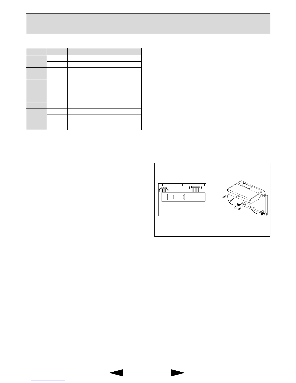
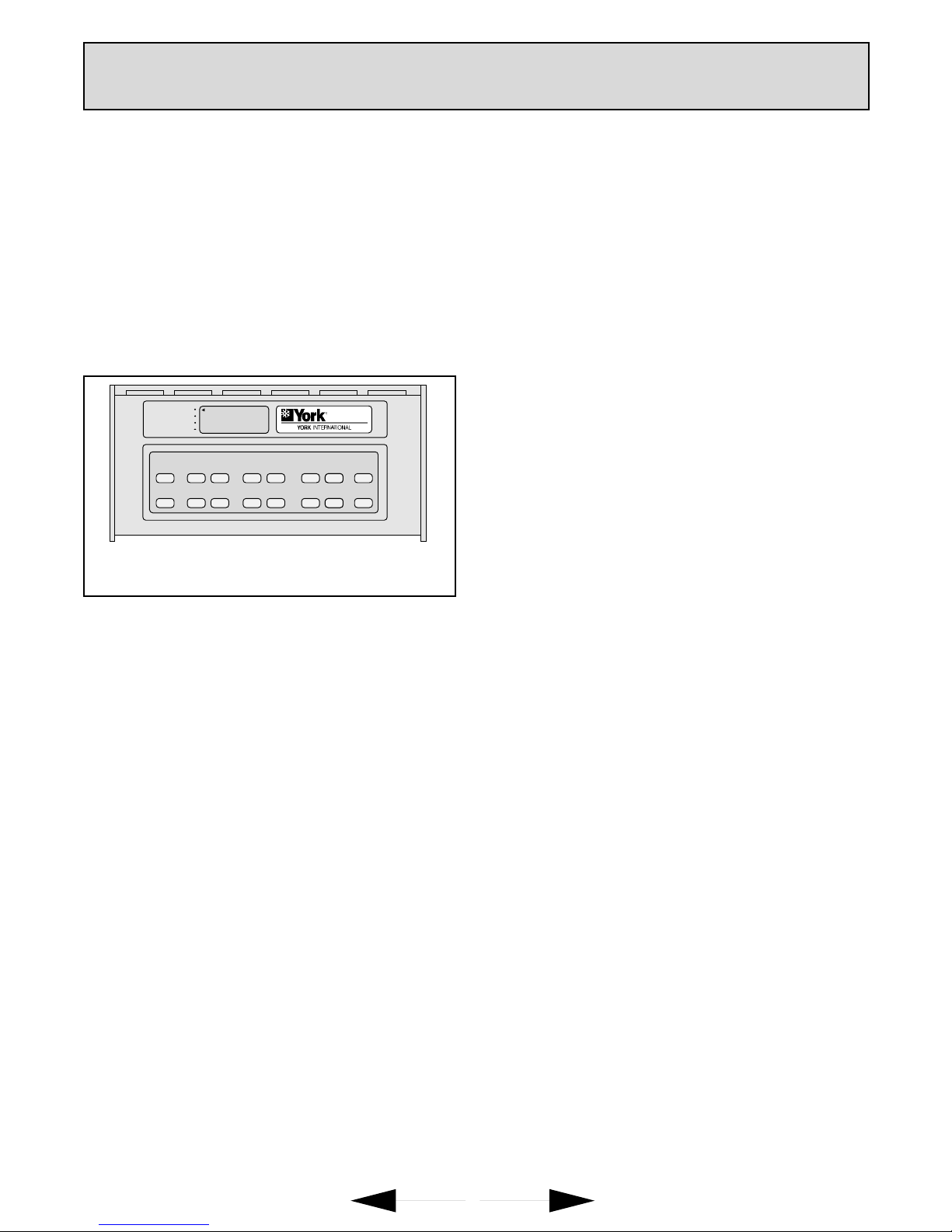
The keyboard is located behind the thermostat flip-up cover. See
Fig. 6. There are 16 keys to set, review and modify programmed
times and temperatures. The liquid crystal display (LCD) shows
day, time or temperature and which programming period
is operating.
The thermostat can be set for two occupied and two unoccupied
time and temperatures for each day of the week (28 independent
settings). The two override keys provide quick temporary pro-
gramming changes for increased occupant comfort.
Important :
To program the thermostat, 24 Vac is required (turn
on System power) and the keyboard lockout swit-
ch (see Fig. 4) must be in the ON-KEYBD position.
4.2 - Set current time/day
1.
Set the current time by pressing and releasing the CLOCK
key once.
2.
Press the + or - key until the current time appears on the LCD.
3.
Set the current day by pressing and releasing the DAY key once.
4.
Press the + or - key until the current day appears on the LCD.
Note :
Su = Sunday; Mo = Monday; Tu = Tuesday; We =
Wednesday; Th = Thursday; Fr = Friday; Sa = Saturday.
4.3 - Set program times
Important :
The thermostat will remain in occupied mode from
the point of initial programming until it encounters
the first unoccupied start time. To avoid the unne-
cessary occupied period following initial program-
ming, set a 12:00 AM unoccupied start time on the
thermostat when programmed.
Note :
The programming times are in intervals of ten minutes;
i.e., 8:00, 8:10, 8:20...
1.
Press the SELECT DAY key. The display shows the abbre-
viation for a day.
2.
Press and hold the + or - key until the desired day appears.
3.
Press the OCCUPIED START TIME key. The program indi-
cator will point to OCCUPIED.
4.
Press and hold the + or - key until the desired start time
appears.
Note :
If a start time is not required, press the CLEAR START
TIME key.
5.
Press the UNOC START TIME key. The program indicator
will point to UNOCCUPIED.
6.
Press and hold the + or - key until the desired start time
appears.
7.
To program a second occupied start time for the selected day,
repeat Step 3 until four dashes ( ---- ) are displayed or the
second start time (if previously programmed) is displayed.
Then repeat Step 4.
8.
To program a second unoccupied start time for the selected
day, repeat Step 5 until four dashes ( ---- ) are displayed or the
second start time (if previously programmed) is displayed.
Then repeat Step 6.
9.
Repeat Steps l through 8 for each remaining day of the week
or refer to the following section, COPY A DAY.
4.4 - Copy a day
1.
Press the SELECT DAY key. The display shows the abbre-
viation for a day.
2.
Press and hold the + or - key until the day to be copied from
appears.
3.
Press the COPY key.
4.
Press and hold the + or - key until the day to be copied to
appears.
Note :
The day to be copied from will remain on the display.
5.
Press the COPY key a second time to perform the copy.
6.
Repeat Steps 3 to 5 to copy to another day.
4.5 - Set program temperature setpoints
Note :
The setpoint temperature range is 7°C (unoccupied heat)
to 35°C (unoccupied cool). The occupied heat setpoint
must be at least 1°C less than the occupied cool setpoint
1.
Press the SET TEMPERATURE key (OCCUPIED HEAT,
OCCUPIED COOL, UNOC HEAT, or UNOC COOL). The
program indicator will point to OCCUPIED or UNOCCUPIED
and the LCD will indicate HEAT or COOL.
2.
Press and hold the + or - key until the desired temperaure
appears.
3.
Repeat Steps 1 and 2 until all four temperatures are set.
4.6 - Set operating display
The LCD can show time or temperature. To change the current
display, press the DISPLAY key until the desired operating dis-
play appears.
4.7 - Clear start time
1.
Press the SELECT DAY key.
2.
Press and hold the + or - key until the desired day appears.
3.
Press and hold the OCCUPIED START TIME or the UNOC
START TIME key until the time to clear appears.
4.
Press and hold the CLEAR START TIME key until the display
shows four dashes ( ---- ).
Note :
If there is a second OCCUPIED setting, the start for time
this setting will appear instead of four dashes.
4.8 - Temporarily override program
There are three overrides available. The 3 hour occupied over-
rides can be initiated from the thermostat.
3 hour occupied
The 3 HOUR OCCUPIED key is used to override the unoccupied
program when people need to use the area temporarily (working
late, weekends or holidays).
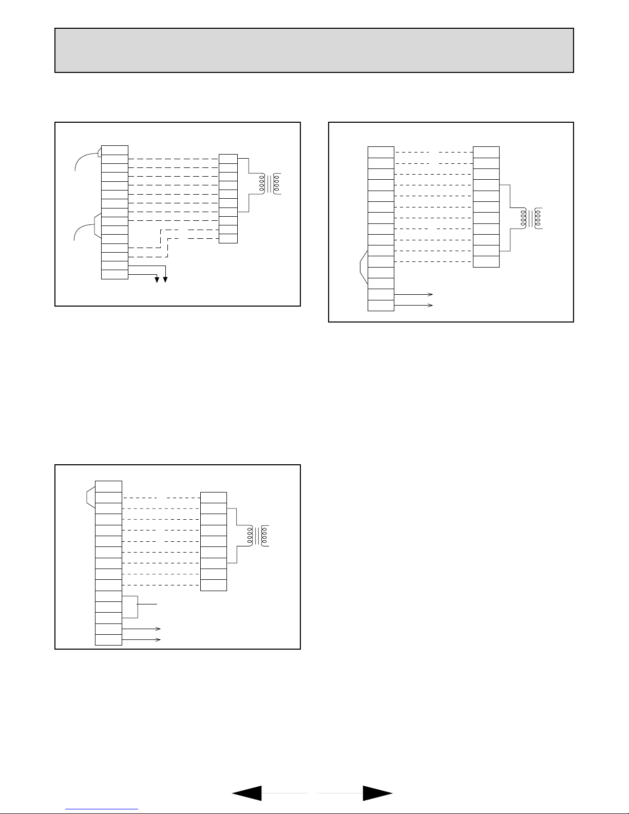
SET START TIMESET SET TEMPERATURE DATA CHANGE OVERRIDE
CLOCK SELECT
DAY OCCUPIED
START TIME OCCUPIED
HEAT OCCUPIED
COOL DISPLAY + 3 HOUR
OCCUPIED
DAY COPY UNOC
START TIME UNOC
HEAT UNOC
COOL CLEAR
START TIME - CONT
UNOC
OCCUPIED
UNOCCUPIED
CONT UNOC
3 HR OCCUPIED
HEAT
AM
11:32
Fig. 6 - Programming keys and LCD

8
4 - Program the thermostat (Cont’d)
1.
Press the 3 HOUR OCCUPIED key to change the unoccupied
temperature setting to the occupied setpoint for three hours.
Note :
The program indicator will point to 3 HR OCCUPIED while
the override is in effect.
3 hour occupied with + or - Key
When using the + or - key with the 3 HOUR OCCUPIED key, the
+ or - key has a preassigned value of 0 to 3°C (default is 0). Use
the following steps to check or change the value:
1.
Press the 3 HOUR OCCUPIED key. The program indicator
will point to 3 HR OCCUPIED.
2.
Press the DISPLAY key. The LCD will show a number from 0
to 3.
3.
Press the + or - key to change the value.
4.
Press the DISPLAY key to return to the program.
Set 3 hour occupied Override With + or - Key
The 3 HOUR OCCUPIED key with the + or - key will override the
unoccupied program for three hours with the occupied tempera-
ture setpoint +/- the preassigned key value (see Set + or - Key
Value section).
1.
Press the 3 HOUR OCCUPIED key to change the unoccupied
temperature setting to the occupied setpoint for three hours.
2.
Press the + key to increase or press the - key to decrease the
occupied setpoint by the key value.
Example :
Unoccupied setpoint is 17°C, occupied setpoint is
21°C and key value is 1,7°C. Pressing the 3 HOUR
OCCUPIED key and the + key will change the set-
point from 17°C to 21°C plus 1,7°C or ~23°C.
Pressing the - key would change the setpoint to
21°C minus 1,7°C or ~19°C.
Note :
The program indicator will point to 3 HR OCCUPIED
while the override is in effect. The LCD will not reflect the
key value.
4.9 - Cont Unoc
The continuous unoccupied override feature holds the setpoint at
the unoccupied temperature setpoint until the DISPLAY or CONT
UNOC key is pressed. This override is used when the area will
be closed for a temporary period such as a long holiday.
1.
Press the CONT UNOC key to hold the temperature at the
unoccupied setpoint.
2.
Press the CONT UNOC key again to return to the program.


Europe
Simplified Diagram
Notes
CUSTOMER INSTALLATION
UNITARY equipment


Printed in France
Manufacturer reserves the right to change specifications without prior notice.
E - UG - R9702
Europe
This manual suits for next models
2
Table of contents
Other York Thermostat manuals