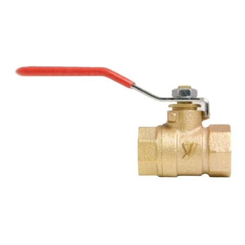
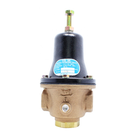
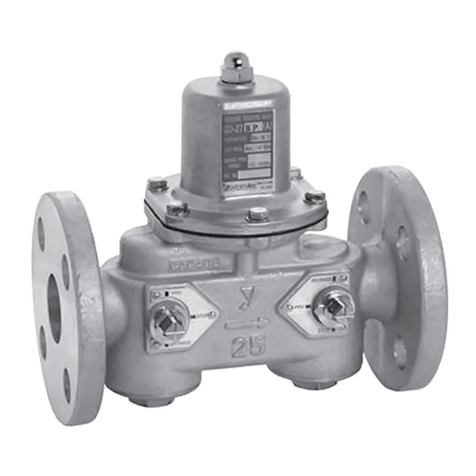
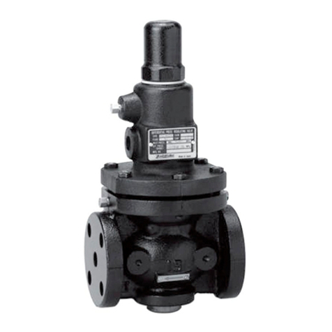
Yoshitake GDK-2000 User manual
Other Yoshitake Control Unit manuals
Yoshitake
Yoshitake GLV-10F User manual

Yoshitake
Yoshitake TA-18ML User manual
Yoshitake
Yoshitake PD-1 User manual
Yoshitake
Yoshitake DP-100 Series User manual
Yoshitake
Yoshitake BSV-10F User manual

Yoshitake
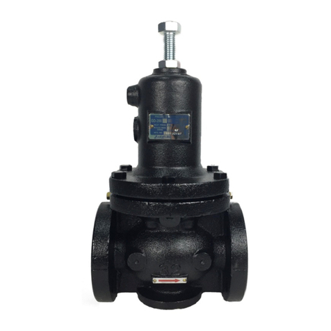
Yoshitake GD-28S-NE User manual
Yoshitake
Yoshitake GD-200 Series User manual
Yoshitake
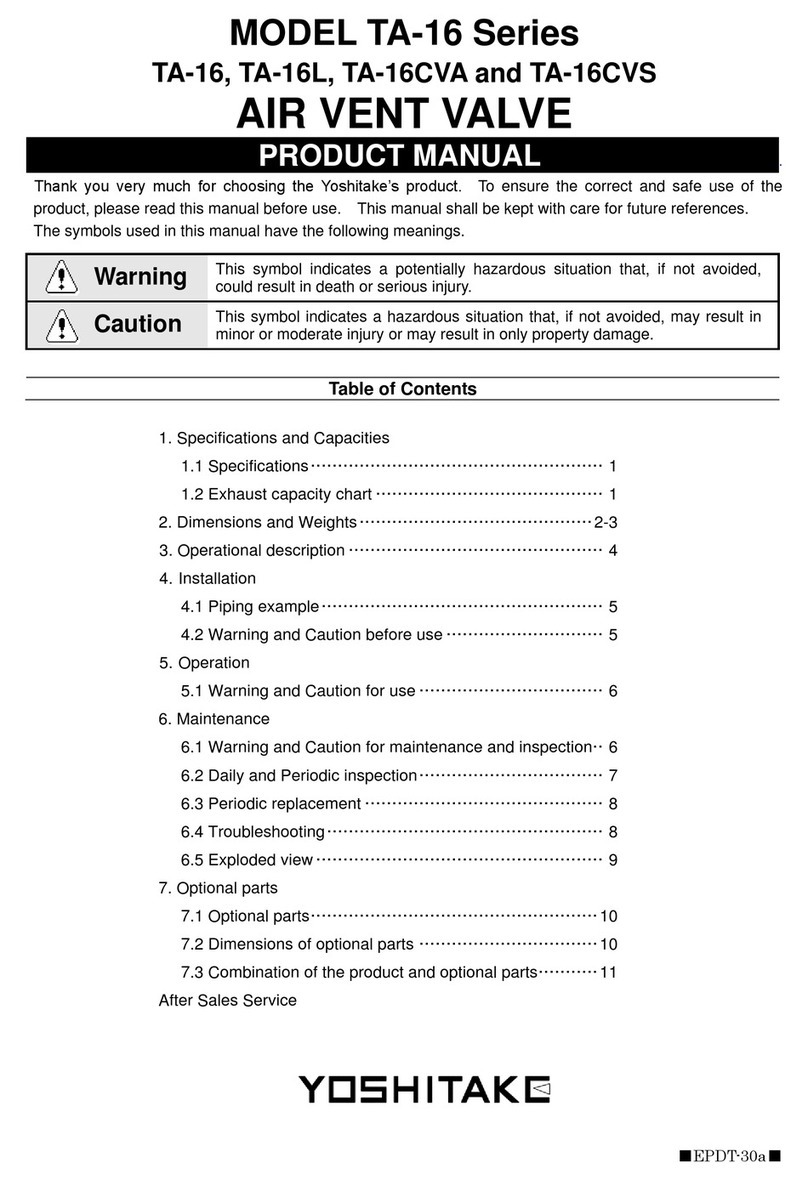
Yoshitake TA-16 Series User manual

Yoshitake
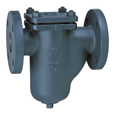
Yoshitake DP-200 Series User manual
Yoshitake
Yoshitake SU-20H User manual

Yoshitake
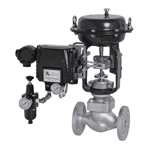
Yoshitake AL-6 User manual
Yoshitake
Yoshitake CT-1 User manual
Yoshitake
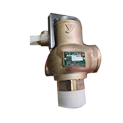
Yoshitake AF-5 User manual
Yoshitake
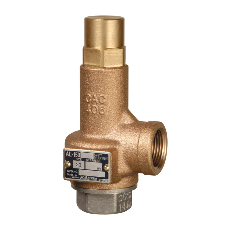
Yoshitake AL-150T Series User manual
Yoshitake
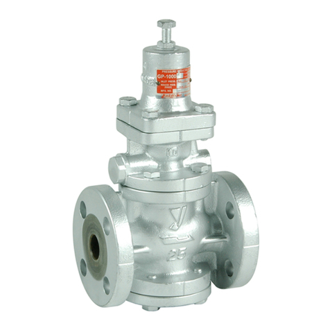
Yoshitake GP-1000 User manual
Yoshitake
Yoshitake TA-22ML User manual

Yoshitake
Yoshitake AL-250 User manual
Yoshitake
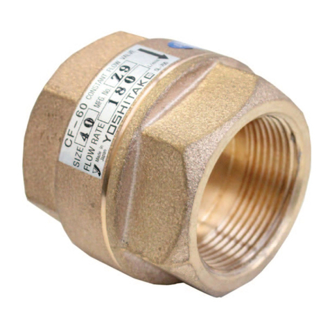
Yoshitake CF-60 User manual
Yoshitake
Yoshitake BFV-1S User manual
Yoshitake
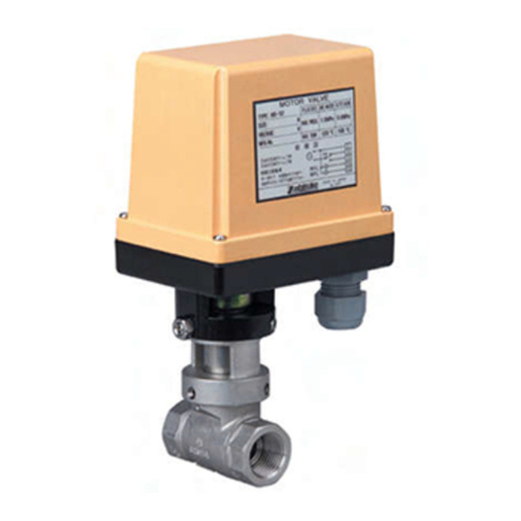
Yoshitake MD-53 User manual
Popular Control Unit manuals by other brands

Festo
Festo Compact Performance CP-FB6-E Brief description

Elo TouchSystems
Elo TouchSystems DMS-SA19P-EXTME Quick installation guide

JS Automation
JS Automation MPC3034A user manual

JAUDT
JAUDT SW GII 6406 Series Translation of the original operating instructions

Spektrum
Spektrum Air Module System manual

BOC Edwards
BOC Edwards Q Series instruction manual

KHADAS
KHADAS BT Magic quick start

Etherma
Etherma eNEXHO-IL Assembly and operating instructions

PMFoundations
PMFoundations Attenuverter Assembly guide

GEA
GEA VARIVENT Operating instruction

Walther Systemtechnik
Walther Systemtechnik VMS-05 Assembly instructions

Altronix
Altronix LINQ8PD Installation and programming manual
