manuals.online logo
Brands
  1. Home
  2. •
  3. Brands
  4. •
  5. Crestron
  6. •
  7. Control Unit
  8. •
  9. Crestron CEN-IO-COM-102 User manual

Crestron CEN-IO-COM-102 User manual

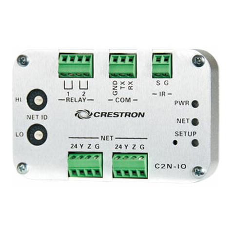
Quick Start
The Crestron® CEN-IO-COM-102, CEN-IO-DIGIN-104, CEN-
IO-IR-104, and CEN-IO-RY-104 allow for easy expansion of
I/O ports within a system. Distribute these wired Ethernet
modules anywhere in the installation via an available LAN
connection.
The CEN-IO-COM-102, CEN-IO-DIGIN-104, CEN-IO-IR-104,
and CEN-IO-RY-104 share a similar installation procedure.
For simplicity within this guide, the term CEN-IO is used
except where noted.
Check the Box
Item Qty
CEN-IO-COM-102, CEN-IO-DIGIN-104,
CEN-IO-IR-104, or CEN-IO-RY-104
1
Bracket, Mounting, Integrated DIN Rail Clip,
Black (P/N 4519035)
1
Screw, 6-32 x 3/8”, Pan Head, Phillips, Black
(P/N 2007225)
2
CEN-IO-COM-102 Only
Connector, 5-Pin (P/N 2003577) 2
CEN-IO-DIGIN-104 Only
Connector, 5-Pin (P/N 2003577) 1
CEN-IO-IR-104 and CEN-IO-RY-104 Only
Connector, 8-Pin (P/N 2003580) 1
Install the Device
The Crestron® wired Ethernet module can be mounted on a
DIN rail, mounted to any flat surface, or placed onto a flat
surface. If necessary, use screws that are suitable for the
mounting surface with a minimum head size of 6.5 mm.
NOTE: The wired Ethernet module can also be rack
mounted. For rack mount installation, refer to
the RMK-IFE-1U Installation Guide (Doc. 7615) at
www.crestron.com/manuals.
DIN Rail Mounting
DIN rail
Mounting
bracket
Screws (2)
CEN-IO
NOTE: When mounting the device to a DIN rail, do not use
the supplied screws to mount the bracket to the bottom of
the wired Ethernet module. Removing the module from the
DIN rail will not be possible.
Flat Surface Mounting
Flat
surface
Mounting
bracket
Screws (2)
CEN-IO
Connect the Device
NOTE: Use PoE derived from a UL Listed source having
LPS/Class 2 outputs.
Crestron provides four wired Ethernet modules. Each offers
a different input/output connection. Modules are powered
via Power over Ethernet (PoE). A ground screw is available,
if needed.
CEN-IO-COM-102 Connections
LAN PoE:
Power and
10BASE-T /
100BASE-TX
Ethernet from a
PoE injector or
Crestron control
system
COM:
To
RS-232
devices
Ground
CEN-IO-DIGIN-104 Connections
LAN PoE:
Power and
10BASE-T /
100BASE-TX
Ethernet from a
PoE injector or
Crestron control
system
DIGITAL
IN (1-4):
From
control
devices
Ground
CEN‐IO-COM-102/CEN‐IO-DIGIN-104/CEN‐IO-IR-104/CEN‐IO-RY-104
Wired Ethernet Modules
CEN-IO-IR-104 Connections
LAN PoE:
Power and
10BASE-T /
100BASE-TX
Ethernet from a
PoE injector or
Crestron control
system
IR:
To IRP2
or 1-way
(TTL)
serial
devices
Ground
CEN-IO-RY-104 Connections
LAN PoE:
Power and
10BASE-T /
100BASE-TX
Ethernet from a
PoE injector or
Crestron control
system
RELAY (1-4):
To
controllable
devices
Ground
Observe the LED Indicators
LED indicators appear on the front and rear panels.
LED Indicator Color Meaning
LAN PoE
(dual color)
Amber Ethernet activity
Green Ethernet link status
ONLINE Green Connection to a Crestron control
system via Ethernet
PWR (dual
color)
Amber Power on, not ready
Green Ready to operate
SETUP
(with recessed
pushbutton)
Red SETUP pushbutton is pressed,
times out automatically*
* To set a different IP address for the module, use the Crestron
Toolbox™ application.
Configure the Device
Configure device settings for the CEN-IO using the web
configuration interface. To access the web configuration
interface:
1. Connect the CEN-IO to a LAN.
2. Use the Device Discovery tool in Crestron Toolbox™
software to discover the device and its IP address on
the network.
3. Open a text console window and use the console
command (SSL SELF) to turn on SSL.
4. Reboot the device.
5. Enter the device IP address into a web browser to
access the first screen. By default, DHCP is enabled.
6. Log in to the web interface using a user name and
password. The default user name and password are
both admin.
For more information on configuring the device, refer
to the CEN-IO Configuration Guide (Doc. 8419) at
www.crestron.com/manuals.
Additional Information
Scan or click the QR code for detailed product information
on the Crestron website.
CEN-IO-COM-102 CEN-IO-DIGIN-104
CEN-IO-IR-104 CEN-IO-RY-104
Compliance and Legal
This product is Listed to applicable UL® Standards and requirements tested by
Underwriters Laboratories Inc.
Ce produit est homologué selon les normes et les exigences UL applicables par
Underwriters Laboratories Inc.
As of the date of manufacture, the product has been tested and found to
comply with specifications for CE marking.
PoE connection is for intra-building onnection only and will not be routed
outside.
La connexion PoE concerne uniquement les connexions intra-bâtiment et ne
sera pas acheminée vers l’extérieur.
Federal Communications Commission (FCC) Compliance Statement
This device complies with part 15 of the FCC Rules. Operation is subject to the
following conditions:(1) This device may not cause harmful interference and (2)
this device must accept any interference received, including interference that
may cause undesired operation.
CAUTION: Changes or modifications not expressly approved by the
manufacturer responsible for compliance could void the user’s authority to
operate the equipment.
NOTE: This equipment has been tested and found to comply with the limits
for a Class B digital device, pursuant to part 15 of the FCC Rules. These limits
are designed to provide reasonable protection against harmful interference
in a residential installation. This equipment generates, uses and can radiate
radio frequency energy and, if not installed and used in accordance with
the instructions, may cause harmful interference to radio communications.
However, there is no guarantee that interference will not occur in a particular
installation. If this equipment does cause harmful interference to radio or
television reception, which can be determined by turning the equipment off and
on, the user is encouraged to try to correct the interference by one or more of
the following measures:
• Reorient or relocate the receiving antenna.
• Increase the separation between the equipment and receiver.
• Connect the equipment into an outlet on a circuit different from that to
which the receiver is connected.
• Consult the dealer or an experienced radio/TV technician for help.
Industry Canada (IC) Compliance Statement
CAN ICES-3 (B)/NMB-3(B)
The product warranty can be found at www.crestron.com/warranty.
The specific patents that cover Crestron products are listed at
www.crestron.com/legal/patents.
Certain Crestron products contain open source software. For specific
information, please visit www.crestron.com/opensource.
Crestron, the Crestron logo, and Crestron Toolbox are either trademarks or
registered trademarks of Crestron Electronics, Inc. in the United States and/
or other countries. UL and the UL logo are either trademarks or registered
trademarks of Underwriters Laboratories, Inc. in the United States and/or
other countries. Other trademarks, registered trademarks, and trade names
may be used in this document to refer to either the entities claiming the marks
and names or their products. Crestron disclaims any proprietary interest in the
marks and names of others. Crestron is not responsible for errors in typography
or photography.
©2018 Crestron Electronics, Inc.
Crestron Electronics, Inc.
15 Volvo Drive, Rockleigh, NJ 07647
Tel: 888.CRESTRON
Fax: 201.767.7576
www.crestron.com
Quick Start - Doc. 7870A
(2047938)
11.18
Specifications subject to
change without notice.
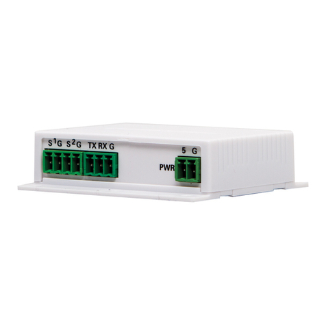
This manual suits for next models

3

Other Crestron Control Unit manuals

Crestron BiAmp AudiaFlex User manual

Crestron

Crestron BiAmp AudiaFlex User manual

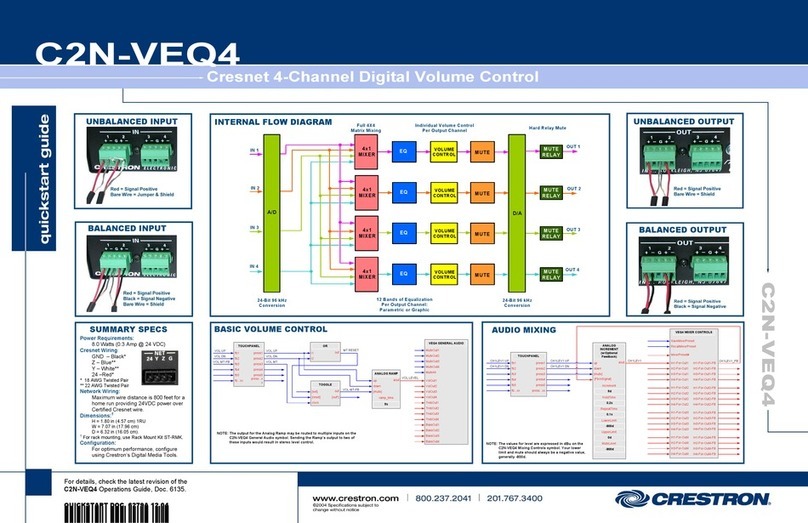
Crestron C2N-FTB How to use

Crestron

Crestron C2N-FTB How to use

Crestron GLS-EM-MCU User manual

Crestron

Crestron GLS-EM-MCU User manual

Crestron FT2A-CHGR-USBA/C User manual

Crestron

Crestron FT2A-CHGR-USBA/C User manual

Crestron C2N-FT-TPS4 How to use

Crestron

Crestron C2N-FT-TPS4 How to use

Crestron FT2A-PWR 1-C14 Series User manual

Crestron

Crestron FT2A-PWR 1-C14 Series User manual

Crestron CNTV User manual

Crestron

Crestron CNTV User manual

Crestron CP3 User manual

Crestron

Crestron CP3 User manual

Crestron FT2A-PWR-UK-1-C14 User manual

Crestron

Crestron FT2A-PWR-UK-1-C14 User manual

Crestron FT2A-PWR-UN-1-C14 User manual

Crestron

Crestron FT2A-PWR-UN-1-C14 User manual

Crestron INET-IOEX-IRCOM User manual

Crestron

Crestron INET-IOEX-IRCOM User manual

Crestron APAD User manual

Crestron

Crestron APAD User manual

Crestron TS-1542-IMCW User manual

Crestron

Crestron TS-1542-IMCW User manual

Crestron APAD User instructions

Crestron

Crestron APAD User instructions

Crestron FlipTop FT2 Series User manual

Crestron

Crestron FlipTop FT2 Series User manual

Crestron SFP-10G-S-U Dimensional drawing

Crestron

Crestron SFP-10G-S-U Dimensional drawing

Crestron CWD6790R1 User manual

Crestron

Crestron CWD6790R1 User manual

Crestron FT2A-PWR-UK Series User manual

Crestron

Crestron FT2A-PWR-UK Series User manual

Crestron FT2A-PWR US Series User manual

Crestron

Crestron FT2A-PWR US Series User manual

Crestron FlipTop FT2 Series User manual

Crestron

Crestron FlipTop FT2 Series User manual

Crestron CWD6609 User manual

Crestron

Crestron CWD6609 User manual

Crestron DIN-AO8 Original operating instructions

Crestron

Crestron DIN-AO8 Original operating instructions

Crestron CWD6671 User manual

Crestron

Crestron CWD6671 User manual

Crestron DMPS3-4K-250-C Dimensional drawing

Crestron

Crestron DMPS3-4K-250-C Dimensional drawing

Popular Control Unit manuals by other brands

Encore Linear ENC-DRS Quick user guide

Encore

Encore Linear ENC-DRS Quick user guide

SVF FS7 Series Installation, Operation and Maintenace Manual

SVF

SVF FS7 Series Installation, Operation and Maintenace Manual

Spectrum Digital eZdsp F2808 Technical reference

Spectrum Digital

Spectrum Digital eZdsp F2808 Technical reference

EB TECHNOLOGY Nologo START-S102 Instruction and warnings for the installer

EB TECHNOLOGY

EB TECHNOLOGY Nologo START-S102 Instruction and warnings for the installer

Busch-Jaeger 6730 manual

Busch-Jaeger

Busch-Jaeger 6730 manual

QTS AN-X2-AB-SCAN user manual

QTS

QTS AN-X2-AB-SCAN user manual

tau D749MA-R installation guide

tau

tau D749MA-R installation guide

GFI Kerio Control Box NG510 quick start guide

GFI

GFI Kerio Control Box NG510 quick start guide

Tyco ACC-1 Operation manual

Tyco

Tyco ACC-1 Operation manual

Honeywell NOTIFIER FCM-1 Installation and maintenance instructions

Honeywell

Honeywell NOTIFIER FCM-1 Installation and maintenance instructions

V-Chip Microsystems VT-CC1110-433M user guide

V-Chip Microsystems

V-Chip Microsystems VT-CC1110-433M user guide

Puls DIMENSION U Series instructions

Puls

Puls DIMENSION U Series instructions

ANEP MIDIS Connection instructions

ANEP

ANEP MIDIS Connection instructions

Graco PD44 Setup & operation

Graco

Graco PD44 Setup & operation

Samson 41-23 Series Mounting and operating instructions

Samson

Samson 41-23 Series Mounting and operating instructions

HEIDENHAIN EXE 808B Replacing Instructions

HEIDENHAIN

HEIDENHAIN EXE 808B Replacing Instructions

Ross Controls DM2C Series manual

Ross Controls

Ross Controls DM2C Series manual

Sandpiper HDF4-A Service & operating manual

Sandpiper

Sandpiper HDF4-A Service & operating manual

manuals.online logo
manuals.online logoBrands
  • About & Mission
  • Contact us
  • Privacy Policy
  • Terms and Conditions

Copyright 2025 Manuals.Online. All Rights Reserved.