Yuasa NP Series User manual

YUASA
NP
VALVE REGULATED
LEAD ACID BATTERY
MANUAL
YUASA

– 1 –
Yuasa began development of the NP series of valve
regulated lead acid batteries in 1958. Today’s NP battery
is the culmination of over 75 years of battery
manufacturing experience.
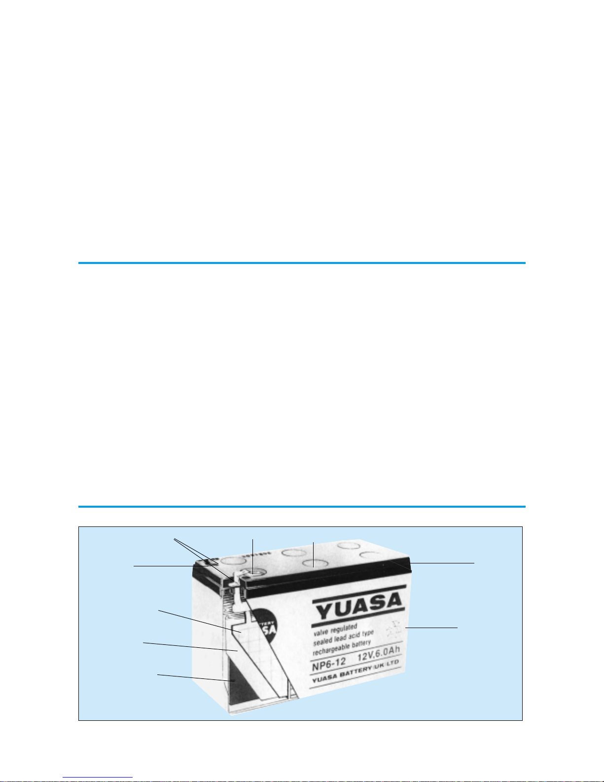
•Sealed Construction . . . . . . . . . . . . . . Yuasa’s unique construction and sealing technique ensures that no electrolyte
leakage should occur from the terminals or case of any NP battery. This
feature provides for safe and effective operation of NP batteries in any
orientation. Yuasa NP batteries are classified as “Non-Spillable” and meet
all requirements of the International Air Transport Association. (I.A.T.A.
Dangerous Goods Regulations), to allow transportation by air.
•Electrolyte Suspension System All Yuasa NP batteries utilise an electrolyte suspension system consisting of
a glass fibre separator material. This suspension system helps to achieve
maximum service life, by fully retaining the electrolyte and preventing its escape
from the separator material. No silica gels or other contaminents are used.
•Gas Generation . . . . . . . . . . . . . . . . . NP batteries incorporate a unique Yuasa design that effectively recombines
over 99% of the gas generated during normal usage.
•Low Maintenance Operation . . . . . . . During the life of NP batteries, there is no need to check their specific gravity
or add water etc. In fact, there are no provisions for such maintenance
functions to be carried out.
•Operation In Any Orientation . . . . . . The combination of sealed construction and Yuasa’s electrolyte suspension
system permits operation of NP batteries in any orientation (excluding continuous
inverted use) without loss of capacity, electrolyte, or service life. The NP batteries
made in our factory in Wales also conform to BS EN61056-1 (1993) and IEC 1056-
1 (1991).
•Low Pressure Venting System . . . . . Yuasa NP batteries are equipped with a safe, low pressure venting system,
which is designed to release excess gas and reseal automatically in the event of
the internal gas pressure rising to an unacceptable level. This low pressure
venting system, coupled with the significantly high recombination efficiency,
make Yuasa NP batteries one of the safest valve regulated lead acid batteries
available.
•Heavy Duty Grids . . . . . . . . . . . . . . . The heavy duty lead calcium alloy grids in NP batteries provide an extra
margin of performance and service life in both float and cyclic applications,
even in conditions of deep discharge.
•Cyclic Service Life . . . . . . . . . . . . . . . Depending upon the average depth of discharge, over 1,000 discharge/
recharge cycles can be expected from NP batteries.
•Float Service Life . . . . . . . . . . . . . . . . . The expected service life of the standard model NP battery when used in stand-
by applications is typically 5 years; however, experience has shown that their
service life often exceeds 6 years, if the NP batteries are operated strictly within
specification.
ADVANCEMENTS
The high energy density, advanced plate technology,
sealed construction, efficient performance and long
service life combine to make Yuasa NP batteries the most
reliable and versatile valve regulated lead acid batteries
available.
With the progress of modern technology and the specific
development of application requirements, Yuasa has
designed generic NP’s to be application specific with the
introduction of NPC, NPH and NPL product ranges.
NPC is specifically designed to suit the arduous require-
ments of cyclic applications allowing increased cycle life (at
least double the cyclic life of conventional types).
NPH These high performance batteries are specifically
designed for applications requiring high rate discharge and
offer much improved power densities up to 50% more
watts per kilo than conventional NP models when operated
at the 10 minute discharge rate.
NPL Offers up to double the float service life of the conven-
tional NP type battery. Note, these models are available to
BS6290pt4 (1997).
The generic types utilise identical physical designs and
characteristics to the standard NP type in all aspects except
their specific application advancement. This in many cases
allows users to upgrade without major redesign.
INTRODUCTION
TECHNICAL FEATURES

Terminals Relief Valve
Cover
Container
Sealant
Negative Plate
Electrolyte
Retentive
Separator
Positive Plate
Top Cover
APPLICATIONS
YUASA NP BATTERY CONSTRUCTION
•Low Self Discharge -Long Shelf Life . At temperatures of between 20 & 25˚c, the self discharge rate of NP batteries
per month is approximately 3% of their rated capacity. This low self discharge
rate permits storage for up to one year without any appreciable deterioration
of battery performance.
•Operating Temperature Range ........... Yuasa NP batteries can be used over a broad range of ambient temperatures,
allowing considerable flexibility in system design and location.
•High Recovery Capability .................... Yuasa NP batteries have excellent charge acceptance and recovery capability,
even after very deep discharge.
•Quality Assurance ................................ Our U.K. manufacturing plant now has Quality Assurance Standard BS5750
Part 2 EN2900, ISO 9002 together with the M.O.D. Quality Assurance AQAP 4.
A list of some of the more common applications for standby or principal power is given below:
•Alarm Systems •Medical Equipment
•Cable Television •Microprocessor Based Office machines
•Communications Equipment •Portable Cine & Video Lights
•Computers •Power Tools
•Control Equipment •Solar Powered Systems
•Electronic Cash Registers •Telecommunication Systems
•Electronic Test Equipment •Television & Video Recorders
•Emergency Lighting Systems •Toys
•Fire & Security Systems •Uninterruptible Power Supplies
•Geophysical Equipment •Vending Machines
•Marine Equipment
– 2 –

Height over
Terminals (mm)
119
98
54.5
54.5
64
64
105.5
97.5
97.5
97.5
174
61.5
54.5
89/85
64
88
64
64
64
64
106
106
97.5
97.5
167
167
125
170
174
174
240
W(mm)
35.5
50
42.5
25
34
34
47
34
50
50
166
25
48
20
34
51
34
67
67
67
70
70
65
98
75
76
175
165
166
166
172.5
L(mm)
48
102
51
97
134
134
70
151
151
151
350
96
97
150
178
68
178
134
134
134
90
90
151
151
181
181
166
197
350
380
407
(10Hr.)
4.20
9.25
0.93
1.11
2.60
2.78
3.70
6.48
9.25
11.10
120.25
0.74
1.11
1.85
1.90
2.00
2.13
2.60
3.00
3.20
3.70
5.00
6.48
11.10
13.88
16.00
22.20
35.15
60.13
72.15
92.00
Model
NP4.2-4H
NP10-4
NP1-6
NP1.2-6
NP2.8-6
NP3-6
NP4-6
NP7.6
NP10-6
NP12-6
NPL130-6
NP0.8-12
NP1.2-12
NP2-12
NP2.1-12
NPH2-12FR
NP2.3-12
NP2.8-12
NP3.2-12
NPH3.2-12
NP4-12
NPH5-12
NP7-12
NP12-12
NP17-12
NPH16-12
NP24-12
NP38-12
NP65-12
NPL78-12
NPL100-12
Nominal
Voltage Nominal
Capacity (Ah) Dimensions
(V)
4
4
6
6
6
6
6
6
6
6
6
12
12
12
12
12
12
12
12
12
12
12
12
12
12
12
12
12
12
12
12
(20Hr.)
4.4
10.0
1.0
1.2
2.8
3.0
4.0
7.0
10.0
12.0
130.0
0.8
1.2
2.0
2.1
-
2.3
2.8
3.2
-
4.0
-
7.0
12.0
17.0
-
24.0
38.0
65.0
78.0
100.0
Weight
Approx
(Kg)
0.56
1.35
0.25
0.31
0.57
0.63
0.87
1.32
1.98
2.05
23.00
0.35
0.58
0.70
0.82
0.84
0.95
1.12
1.2
1.40
1.75
2.00
2.65
4.05
6.1
6.20
9.0
14.2
23.0
27.5
39
Layout
6
1
5
1
1
1
5
1
1
1
5
9
3
10
1
2
1
3
4
3
1
1
4
4
2
2
2
2
2
2
1
Terminals
Flat
D
A
A
A
A
A
A
A&C
C
K
H
A
B
A
A
A
A
A
A
A&C
D
A&C
D
J&E
E
J&E
J&F
K&G
K&L
M10 bolt
GENERAL SPECIFICATIONS
– 3 –

Table 2. LAYOUT
– 4 –
Table3. TERMINALS

– 5 –
Figure 2 below may be used to determine the minimum
battery size, expressed in Ampere hours of capacity. To
determine the required minimum battery capacity, plot
the required discharge current, on the horizontal
axis, against time. The point where the current and time
lines intersect on or below the diagonal Ah curve shows
the minimum capacity required for the application. In
practice, if the intersection point of the time & current
does not fall exactly on a particular Ah curve, the next
higher value Ah curve should be used to determine the
minimum battery capacity/size. In addition, it is
recommended that figure 32 (Cyclic Service Life) and
Figure 33 (Float Service Life) and if appropriate, the
constant power calculations in table 5, on page 7, should
be consulted prior to final selection.
Discharge Characteristics
The curves shown in Figure 3 and the discharge
current rates shown in Table 4 illustrate the
typical discharge characteristics of Yuasa NP batteries
at an ambient temperature of 25°. The symbol “C”
expresses the nominal capacity of the battery measured
at a 20-Hour discharge rate. Please refer to General
Specifications on page 3 to determine the nominal
capacity rating of specific NP models. The standard
industry practice to determine the nominal capacity of a
valve regulated lead acid battery is to discharge the battery
under test at its 20-Hour rate to a final voltage of 1.75
volts per cell.
Table 4 shows the different currents that can be drawn
at various discharge capacity rates.
Table 6 shows that the rated nominal capacity of a
battery is reduced when it is discharged at a value of
current that exceeds its 20-Hour discharge rate. This
should be taken into consideration when a battery is
being selected for a particular application.
BATTERY CAPACITY SELECTION
DISCHARGE
FIG 2

3C
2.4 A
3.0
3.6
6.3
6.0
6.9
8.4
9.0
12.0
18.0
21.0
24.0
30.0
36.0
51.0
72.0
114.0
195.0
234.0
390.0
2C
1.6A
2.0
2.4
4.2
4.0
4.6
5.6
6.0
8.0
12.0
14.0
16.0
20.0
24.0
34.0
48.0
76.0
130.0
156.0
260.0
1C
0.8A
1.0
1.2
2.1
2.0
2.3
2.8
3.0
4.0
6.0
7.0
8.0
10.0
12.0
17.0
24.0
38.0
65.0
78.0
130.0
0.6C
0.48 A
0.60
0.72
1.26
1.20
1.38
1.68
1.80
2.40
3.60
4.20
4.80
6.00
7.20
10.20
14.40
22.80
39.00
46.80
78.00
0.4C
0.32A
0.40
0.48
0.84
0.80
0.92
1.12
1.20
1.60
2.40
2.80
3.20
4.00
4.80
6.80
9.60
15.20
26.00
31.20
52.00
0.2C
0.16A
0.20
0.24
0.42
0.40
0.46
0.56
0.60
0.80
1.20
1.40
1.60
2.00
2.40
3.40
4.80
7.60
13.00
15.60
26.00
0.05C
0.04 A
0.05
0.06
0.105
0.10
0.115
0.14
0.15
0.20
0.30
0.35
0.40
0.50
0.60
0.85
1.20
1.90
3.25
3.90
6.50
0.1C
0.08 A
0.10
0.12
0.21
0.20
0.23
0.28
0.30
0.40
0.60
0.70
0.80
1.00
1.20
1.70
2.40
3.80
6.50
7.8
13.00
20 Hr.
Capacity
0.8 Ah
1.0
1.2
2.1
2.0
2.3
2.8
3.0
4.0
6.0
7.0
8.0
10.0
12.0
17.0
24.0
38.0
65.0
78.0
130.0
Discharge Current
Table 4. DISCHARGE CURRENT AT STIPULATED DISCHARGE RATES
– 6 –

– 7 –
Calculation of battery size required for Constant Power load conditions.
Using Table 5 “Watts/Cell/Ah”, map the required load time to the specified end of
discharge voltage. The figure obtained is the Constant Power available from each 1Ah
of NP type cell. Divide this number into the required wattage load per cell to give the
minimum value of capacity required to supply the required load.
Example: 5.3kW load requires 30 minutes standby operating from maximum 272V
down to end of discharge 204V at 25°C.
1. Recommended float voltage for NP batteries at 25°C is 2.26volts per cell. To find
the number of series cells required, divide the maximum load voltage by 2.26v.
272/2.26 = 120 cells
2. Divide the end voltage by the number of cells to find the value of end volts per
cell 204/120 = 1.7vpc
3. Divide specified load by number of cells to find load in watts per cell
5,300/120 =44.17wpc
4. Map end vpc “1.7” against required load time “30 mins” in Table 5:
1.872watts per cell per Ah
5. Divide load in wpc by value from Table 5
44.17/1.872 = 23.59Ah
6. Select the battery from the list on page 3
20 x NP24-12 is the minimum requirement

0.1C or below, or intermittent discharge
0.17C or current close to it
0.26C or current close to it
0.6C or current close to it
Current in excess of 3C
For intermediate values, see figure 3 on page 6
1.75
1.70
1.67
1.60
1.30
see figure 3 on page 6
Table 6. DISCHARGE CAPACITY AT VARIOUS DISCHARGE RATES
– 8 –
Over Discharge (Deep Discharge)
The dotted line in Figure 3 indicates the lowest
recommended voltage under load, or cut off voltage, for
NP batteries at various discharge rates. In general, lead
acid batteries are damaged in terms of capacity and
service life if discharged below the recommended cut off
voltages. It is generally recognised that all lead calcium
alloy grid batteries are subject to over discharge damage.
For example, if a lead acid battery were discharged to
zero volts, and left standing in either “on” or “off” load
conditions for a long period of time, severe sulphation
would occur, raising the internal resistance of the battery
abnormally high. In such an extreme case, the battery
may not accept charge. NP batteries have been designed
to withstand some levels of over-discharge. However,
whilst this is not the recommended way of operation,
Yuasa NP batteries can recover their capacity when
recharged correctly. Final discharge voltage is shown in
Table 7.
Table 7. FINAL DISCHARGE VOLTAGE
If a battery is to be discharged at a rate in excess of
3C Amps, please contact us prior to use.
Discharge Current Final Discharge Voltage (V/Cell)

STORAGE, SELF DISCHARGE and SHELF LIFE
– 9 –
Temperature Characteristics
At higher temperatures, the electrical (Ah) capacity of a
battery increases and conversely at lower temperatures,
the electrical (Ah) capacity of a battery decreases.
Figure 4 shows the effects of different temperatures in
relation to battery capacity.
Self Discharge
The self discharge rate of NP batteries is approximately
3% per month when stored at an ambient temperature of
20°C. The self discharge rate will vary as a function of
ambient storage temperature. Figure 5 shows the
relationship between storage times at various
temperatures and the remaining capacity.

Shelf Life
In general, when lead acid batteries of any type are stored
for extended periods of time, lead sulphate is formed on
the negative plates of the batteries. This phenomenon is
referred to as “sulphation”. Since the lead sulphate acts
as an insulator, it has a direct detrimental effect on charge
acceptance. The more advanced the sulphation, the lower
the charge acceptance.
Table 8 below shows the normal storage time or shelf life
at various ambient temperatures.
Table 8. Shelf Life at Various Temperatures
– 10 –
Brief excursions i.e., a few days, at temperatures higher
than the ranges recommended will have no adverse
effect on storage time or service life. However, should
the higher ambient temperature persist for one month or
more, the storage time must be determined by referring
to the new ambient temperature. Ideally NP batteries
should be stored in dry, cool conditions.
Recharging Stored Batteries
In general, to optimise performance and service life, it is
recommended that NP batteries which are to be stored
for extended periods of time be given a supplementary
charge, commonly referred to as a “top charge”,
periodically. Please refer to the recommendations listed
on page 24 under Top Charging.
Temperature Shelf Life
0°C ( 32°F) to 20°C ( 68°F)
21°C ( 70°C) to 30°C ( 86°F)
31°C ( 88°F) to 40°C (104°F)
41°C (106°F) to 50°C (122°F)
12 months
9 months
5 months
2.5 months

Figure 6 shows extrapolated Service Life condition for
NP batteries at different ambient temperatures. As can
– 11 –
be seen from figure 6 higher ambient temperatures will
reduce service life.

IMPEDANCE
– 12 –
The approximate depth of discharge, or remaining
capacity, in a Yuasa NP battery can be empirically
determined by referring to Figure 7.
The internal resistance (impedance) of a battery is lowest
when the battery is in a fully charged state. The internal
resistance increases gradually during discharge, Figure 8
shows the internal resistance of an NP6-12 battery
measured through a 1,000 Hz AC bridge.
AVAILABLE CAPACITY, MEASURED BY OPEN CIRCUIT VOLTAGE

– 13 –
Impedance testing can be performed using the Yuasa YPI-2
Impedance/comparator test meter, this form of testing is
non-intrusive and can be performed online with the battery
still connected within its system. (Note: The YPI-2 meter can
Note
The recommended float charge voltage for NP type
batteries at 20°C is 2.275vpc ± 0.005v. this should be the
measured average for the total battery, however when
measured within a battery network or string the allowable
tolerances can be expected between 2.25vpc and 2.3vpc.
CHARGING
not be used where a high AC ripple content exists.) By
using this test method deterioration can be detected with-
out removing the battery from its standby mode.
Correct charging is one of the most important factors to
consider when using valve regulated lead acid batteries.
Battery performance and service life will be directly affected
by the efficiency of the charger selected. The basic charging
methods are:
•Constant Voltage Charging
•Constant Current Charging
•Taper Current Charging
•Two Stage Constant Voltage Charging
Constant Voltage Charging
Charging at constant voltage is the most suitable and
commonly used method for charging valve regulated
lead acid batteries. Figures 10 - 15 show the charging
characteristics of NP batteries when charged by constant
voltage chargers at 2.275 volts/cell, 2.40 volts/cell and 2.50
volts/cell when the initial charging current is controlled at
0.1C Amps and 0.25C Amps.
Figure 9 shows one example of a constant voltage charging
circuit. In this circuit, the initial charging current is limited
by the series resistance R1.

– 14 –

– 15 –

– 16 –

– 17 –
Constant Current Charging
This charging method is not often utilised for valve
regulated lead acid batteries, but is an effective method
for charging a number of series connected batteries at
the same time, and/or as an equalising charge to correct
variances in capacity between batteries in a series group.
Extreme care is required when charging NP batteries
with a constant current. If, after the battery has reached a
fully charged state, the charge is continued at the same
rate, for an extended period of time, severe overcharge
may occur, resulting in damage to the battery. Figure 16
shows a typical constant current charging circuit; Figure
17 shows the characteristics of two NP6-12 batteries under
continuous overcharge conditions.

– 18 –
Taper Current Charging
This method of charging is not recommended due to the
constant current characteristics of taper charging being
somewhat harsh on valve regulated lead acid batteries.
This particular charging regime can often shorten battery
service life. However, because of the simplicity of the
circuit and subsequent low cost, taper current charging is
often used to charge a number of series connected
batteries that are subject to cyclic use. When using a
taper charger it is recommended that the charging time
is either limited or that a charging cut-off circuit be
incorporated to prevent overcharge. Please consult us
for specific recommendations.
In a taper current charging circuit, the charging current
decreases gradually and the charging voltage rises
proportionately as the charge progresses. When designing
a taper charger it should be borne in mind that variations
in the mains input supply will be reflected in the output
of the charger. Figure 18 illustrates the characteristics of
a typical taper charger.

– 19 –
Two Stage Constant Voltage Charging
Two stage constant voltage charging is a recommended
method for charging valve regulated lead acid batteries
in a short period of time and then maintaining them in a
fully charged float or standby condition. Figure 20
illustrates the characteristics of a two stage constant
voltage charger.
The characteristics shown in Fig.20 are those of a constant
voltage, current limited charger. In the initial charging
stage, the current flowing into the battery is limited to a
value of 0.25C Amps. The charging voltage across the
battery terminals rises, during the charging process, to a
value equal to the constant voltage output of the charger,
which is set to 2.45 volts per cell. Whilst continuing to
charge, in stage 1 (A-B), at 2.45 volts per cell, the current
will eventually decrease to point “Y”, where the value of
this decreasing current is “sensed” causing the circuit to
switch into the second stage (B-C), reducing the charging
voltage from 2.45 volts per cell to a constant voltage,
float/standby, level of 2.3 volts per cell. The switch to
stage two, where the constant voltage level of 2.3 volts
per cell is applied, occurs after the battery has recovered
about 80% of its rated capacity. This is one of the most
efficient charging methods available as the recharge time
is minimised during the initial stage whilst the battery is
protected from overcharge by the system switching to
stage 2 (float/standby) charge at the switching point “Y”.
When this charging method is used, the output values
will be as follows:
Initial Charge Current . . . . . 0.25C Amps (max).
Charge Voltage:-
1st Stage . . . . . . . . .2.45v/cell (2.40 to 2.50 v/cell, max.)
2nd Stage . . . . . . .2.27vpc ± 0.005
Switching Current From
1st Stage to 2nd Stage . . . . . . . . . . 0.05C Amps
(0.04C to 0.08C Amps)
Note: This charging method cannot be used in applica-
tions where the load and the battery are connected
in parallel.
Other manuals for NP Series
1
This manual suits for next models
29
Table of contents
Other Yuasa Camera Accessories manuals