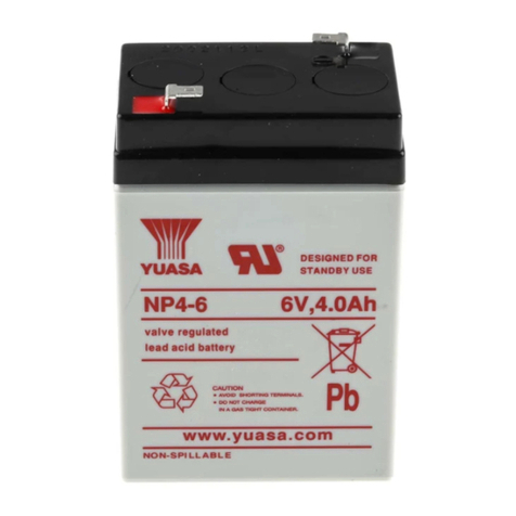
Yuasa NP Series Installation guide

INSTALLATION,
USE AND AUTONOMY
TRIAL INSTRUCTIONS
YUASA BATTERIES
NP/NPL/SW/
SWL/EN/ENL/UXL/FXH/YFT/YUCEL

2
CONTENTS
1/ FITTERS AND PERSONS HANDLING page 3
YUASA BATTERIES
2/ RISKS AND SAFETY MEASURES page 3
3/ RECEIPT OF A DELIVERY page 5
4/ STORAGE BEFORE INSTALLATION page 6
5/ GENERAL INSTALLATION CONDITIONS page 7
6/ INSTALLATION IN CABINETS OR ON YUASA STANDS page 9
7/ ELECTRICAL CONNECTIONS page 10
8/ CHARGE page 13
9/ DISCHARGE page 14
10/ CLEANING page 14
11/ RECOVERING USED BATTERIES (LEAD) page 14
12/ AUTONOMYTEST METHOD DURING COMMISSIONING page 16

3
This guide is for anyone installing YUASA
NP/NPL/SW/SWL/EN/ENL/UXL/FXH/YFT/YUCEL batteries or called upon to work
with these batteries. Information refer to industrial batteries installation and
operation standard EN50272-2, NFC15-100.
1/ FITTERS OR PERSONS HANDLING YUASA BATTERIES
Staff installing or guaranteeing the maintenance of any battery must be
authorised to work with live batteries in accordance with the UTE C 18-510 (or local
equivalent) standard.
They must be trained and equipped in such a way as to be able to apply all the
necessary safety measures described in this document.
Staff involved in such tasks must also respect the safety measures specific to the
place of the installation or intervention (prevention plan). Take care about alone work
conditions.
2/ RISKS AND SAFETY MEASURES
This danger symbol will figure in this document to indicate all the
messages relating to staff safety.
WARNING !
Before unwrapping, transporting, installing or handling YUASA VRLA batteries,
read carefully this paragraph on RISKS and SAFETY MEASURES, as well as all
the paragraphs in which the danger symbol appears.
2-1/ DESIGN/APPLICATION TIPS TO ENSURE MAXIMUM SERVICE
UL Cautionary Statement:
WARNING: Risk of fire, explosion or burns. Do not disassemble, heat above
50°C, or incinerate.
2-2/ RISK OF SULPHURIC ACID BURNS
The batteries contain sulphuric acid which can cause burns and other injuries.

4
In case of contact with the skin or eyes, rinse abundantly with water and
consult a doctor.
When handling the batteries for any reason, wear rubber gloves, safety helmet
( with visor) and make sure to be equipped with an individual eye-bath.
The acid also burns clothing. It is recommended that acid-resistant aprons or
clothing be worn.
2-3/ RISK OF GAS EXPLOSIONS
The batteries may generate gases (including hydrogen). These gases are
capable of being ignited and causing explosions which may cause deafness,
blindness or other injuries.
For example, if the charger/rectifier develops a fault or is incorrectly adjusted,
explosive gases may be released through the safety relief valves of the cells or
monoblocs of the battery.
Any form of spark (static electricity or other), all flames and short-circuits must
be forbidden.
Do not use plastic walkways.
Do not smoke in or near the battery room.
2-4/ RISK OF ELECTROCUTION AND BURNS
A battery composed of several cells or monobloc units connected in series can
reach dangerously high voltage levels.
All measures must be taken during the installation or intervention in order to
avoid any risk of electrocution or electrical burn.
Use insulated tools (in accordance with the NFEN 60 900 or IEC 60900 or
local equivalent) when installing or handling the batteries.
Never place metallic tools or objects on the batteries in order to avoid any risk
of short-circuit, electrocution or electrical burn.
Remove all metallic chains, watches, rings and bracelets if possible; otherwise
ensure they are insulated.
Wear insulating gloves and safety glasses. Insulate yourself from the ground
with an insulating mat, wooden walkway or stool for batteries with a potential
difference exceeding 120V.

5
Connectors in bad working condition can provoke fires. Make sure that the
connectors are in good working condition and verify that they are attached to the right
tightening torque.
Disconnect the batteries from the charger/rectifier before any maintenance
work. If necessary, disconnect one part of the batteries in series so that the potential
difference of the whole unit on which the operator is working is not more than 120V.
Mark out the work area to prevent non-authorised persons from entering.
2-5/ LIST OF PROTECTIVE MATERIAL
- Safety helmet (with visor).
- Safety boots.
- Handling gloves.
- Acid-resistant gloves.
- 1000V electrical protection gloves.
- Safety glasses anti-UV (EN166 and 170).
- Insulating mat or insulating stool.
- Anti-static and acid-resistant clothing.
- Insulated tools (NFEN 60 900, IEC 60900 or local equivalent).
- Insulated torque wrench.
- Insulated caps for wire ends.
- Individual eye-bath.
- Marking equipment.
- Lifting tools if necessary.
- Product for neutralising acid (for open batteries).
3/ RECEIPT OF A DELIVERY
3-1/ CONTROLS ON RECEIPT OF THE DELIVERY
Make sure that the number of packages corresponds to the delivery slip.
Make sure that the packages have not been damaged during transportation.
A damaged package may be the result of bad handling.

6
Write a description of any problems noted on the delivery slip before signing. If
the batteries or accessories (stand or rack, cabinet, case, connectors and so on)
have been damaged, ask the driver to witness the damage and immediately inform
the carrier that the delivery has been refused.
All batteries with damaged terminals, damaged cases or any trace of leaked
acid must be replaced.
3-2/ BATTERIES DELIVERED IN CABINETS
On reception, unwrap the cabinet.
Visually verify the condition of the cabinet and the batteries on both the
outside and the inside.
It is advised to check the terminal tightening with an isolated torque key to
avoid all loosening during transportation. To limit this risk we advise to use flexible
inter batteries connectors.
Warning: dangerous voltage levels may be present
Remove any hopping and fixing of the batteries before start up. Space the
batteries to facilitate ventilation if possible.
Anything that does not conform must be informed in writing to YUASA’s
logistics department.
4/ STORAGE BEFORE INSTALLATION
4-1/ STORAGE SITE
If the battery is not installed and recharged immediately after delivery, it is
recommended that it be stored inside, in a clean, dry place at an ambient
temperature (15°C to 30°C).
Do not stack more than 2 pallets of batteries.
All batteries stored at temperatures of more than 30°C will have to be
recharged more quickly. (See the TECHNICAL MANUAL corresponding to the type
of battery).
4-2/ STORAGE DURATION

7
The duration of the storage period, from manufacture date (date-code marked on
the batteries) to the first recharge, must not exceed:
12 months at an ambient temperature of less than 20°C
9 months at an ambient temperature from 21°C to 30°C
5 months at an ambient temperature from 31°C to 40°C
It should be noted that batteries stored at higher temperatures must have a
reduced storage period before recharging.
Storing a battery for longer without recharging it leads to sulphation of the plates.
This reduces the performance and shelf life of the battery. If the battery is stored for
too long it may not recover full performance and/or life. (See the TECHNICAL
MANUAL corresponding to the type of battery).
The respect of these advices allows to store the batteries for few years.
5/ GENERAL INSTALLATION CONDITIONS
The following chapter should be read carefully before starting the installation of
YUASA batteries.
5-1/ POSITION OF THE BATTERY
It is recommended that the battery be installed in a clean, dry and cool place.
The ground must be flat and able to bear the weight of the battery.
Install the battery in a well-ventilated place so as to maintain an ideal
temperature for the battery:
An ambient temperature of 20°C+/-5°C is optimal for the performances and
service life of the battery.
An ambient temperature of less than 20°C reduces the efficiency and
performance of the battery.
An ambient temperature of more than 25°C reduces the service life of the
battery.
During installation of the battery, make sure there is sufficient room around the
battery, the cabinet, stand or the rack. This is to ensure that future interventions for
monitoring or performing maintenance of the battery are easier and safer. Avoid
installations against a site wall or cabinets with more than 3 rows of batteries or more
than 600 mm deep.

8
To allow emergency evacuation an unobstructed escape path shall be
maintained at all times with a minimum of 600 mm.
The installation of other equipment close to the battery must not make access
to the battery difficult.
5-2/ VENTILATION
YUASA NP/NPL/SW/SWL/EN/ENL/UXL/FXH/YFT/YUCEL batteries are
described as Valve Regulated Lead Acid batteries. Under normal floating charge
conditions, very little gas will be released.
YUASA NP/NPL/SW/SWL/EN/ENL/UXL/FXH/YFT/YUCEL batteries have a gas
recombination efficiency of more than 95%.
Good natural ventilation is enough to prevent all dangerous accumulations of
gasses (see standards EN 50 272-2 or NFC15-100).
In case of overcharge, hydrogen and oxygen will be released from the battery. As
a result, the battery must never be installed in a gas-tight enclosure.
Sufficient precautions must be taken to avoid overcharge (monitoring the charge
system).
It is recommended that a space of 5 to 10 mm be provided between each
cell or monobloc to allow for easier ventilation. On site, this space should be
envisaged in the sense of the length of the site (small side of the monoblocs). In
cabinets, where there is less ventilation, at least leave a space between one of the
sides of the monoblocs.
The batteries can be installed near electronic equipment (following EN50272-2
standard). The heat dissipated by such equipment must be evacuated by ventilation.
5-3/ DIFFERENCES IN TEMPERATURE
The differences in temperature of the various cells or monoblocs making up a
battery cause differences in voltage in the same units. This perturbs the
performances of the battery.
External heating, sunlight, a natural air current or air conditioning can all be the
source of a difference in temperature.
Particular attention must be paid to reducing the differences in temperature
between the various cells or monoblocs of a battery.

9
5-4/ FLOOR LOADING
The ground on which the battery will be installed must be able to bear the weight
of the battery, cabinet or case. The total weight is indicated on the assembly plan
supplied by YUASA.
Attention must also be paid to the point loading (weight per stand insulator foot).
5-5/ HANDLING
Depending on the model, the weight of the battery cells or monoblocs can be
significant.
Take all the required precautions involved in installing batteries in cabinets or
stands and use lifting equipment if necessary.
Wear safety shoes, handling gloves and a helmet.
Do not lift the batteries by their terminals (this may rupture the terminal
sealing).
Respect the handling order of the packages.
6/ INSTALLATION IN CABINETS OR ON YUASA STANDS
It should be noted that it is always preferable to install batteries on stands rather than
in cabinets, for the following reasons:
Installation and maintenance both reduced and easier.
More efficient ventilation.
Simplified connections between monoblocs (more single rigid connection links,
less end cables, reduced voltage drops).
Reduced equipment and installation costs.
For the assembly and connections, refer to the documents supplied with the battery:
- Yuasa assembly/wiring plan and nomenclature.
- Instructions for assembly in cabinets or on stands.
Before installing the monoblocs in a cabinet or on site, make sure that the shelves
and beams are stable and well-attached.

10
Verify the homogeneity of the voltages of the monoblocs prior to assembly. Do not
assemble a monobloc with a voltage that is too low.
Within a single string and whenever possible, assemble monoblocs with the same
date code (etched or stuck to the top of the battery).
During installation, make sure that there are no bumps or scrapes that damage the
battery container.
During installation, ensure that there is sufficient space for good ventilation (use a
gauge).
Using the stickers provided, and in accordance with Yuasa’s plan, number the top
of each monobloc, making sure not to conceal the date code of the batteries.
Dip trays are not useful with VRLA batteries.
Yuasa stands are isolated (no need to connect to the ground).
7/ ELECTRICAL CONNECTIONS
7-1/ CONNECTING BETWEEN CELLS OR MONOBLOCS
Use the connectors (cable, bar or braid) adapted to each battery supplied by
YUASA. The flexible connectors can limit the risks of terminal loosening during the
transportation.
The choice of connector should be made in relation to the maximum discharge
current and the drop in voltage to be minimised. The total drop in voltage in this
connector must not exceed 1 % of the nominal battery voltage with nominal current
or power.
The inter-row end cables must be assembled on the batteries to avoid being
loosened by mistake.
The inter-level end cables and other cables must be assembled without stress on
the terminals and can, if necessary, be attached to avoid being loosened by mistake.
No washer between terminals and connectors, risk of high temperature.
The holes in the connectors, end cable or cable eyes must be adapted to the
diameter of the terminal screws supplied with the batteries (+0.5 mm max). For
example, never assemble cable eyes of 8 mm or more with M6 screws. There is a
significant risk of damaging the terminal, leading to poor electrical contacts and acid
leakage.
The terminal screws used must be those provided with the batteries. Always
assemble spring washers under the screw heads and flat washers in contact with the

11
end cables, cable eyes or cables. First screw them in by hand, then use a torque
wrench.
The terminal covers must be assembled on to the screw heads by means of
manual pressure on the cylindrical part, then fold the black cover down on to the top
of the battery.
Safety Requirement: Place the cells or monoblocs in such a way that the
terminals or bare conductor parts having a potential difference of potential of more
than 120V cannot be touched simultaneously by accident.
YES NO
To minimise electrical risks during cabling, here is the recommended method:
a) Choose from the battery string an end cable or cable eye that is easy to
access, and that you will assemble only at the end of the cabling process
after having verified that there is no difference in potential between the 2
terminals.
b) Cable the end cables for each shelf or level.
c) Cable the most difficult to reach cable eyes for each shelf or level, mainly
at the back.
d) Cable the inter-shelf or inter-level cable eyes or cables.
e) Connect the cables to the terminal cabinet, fuses or circuit breaker, making
sure there is no difference in potential between the polarities of the cabinet.
At the end of the cabling, it’s important to check that no electrical potential exists
between cabinet or rack metal-framed and each polarity (+/-) of final batteries.
7-2/ CONNECTING THE BATTERY TO THE APPLICATION
The performance of the battery is measured at the level of its take-off terminals.
As a result, the length of the connections between the battery and the application
must be as short as possible, so as not to affect the efficiency of the unit as a whole.
The section of connectors must not only be chosen on the basis of its current
capacities. The section must also be chosen to minimise the potential difference
between the battery and the application. If the potential difference is too significant,
the expected autonomy of the equipment will be reduced.

12
Generally speaking, the drop in voltage in the cables between the battery and the
application must not exceed 1 % of the nominal battery voltage at nominal current or
power.
For new assemblies, make sure the battery is secure, that is, remove an end
cable per battery string (accessible and visible…) so as to avoid any potential danger
when connecting the battery to the application (terminal, fuses, circuit breaker,
terminal box,…).
Contact YUASA for definitions and supplies.
7-3/ PARALLEL CONNECTION
When several batteries have to be connected in parallel, the choice of section
from the connectors is made in relation to the current and the potential difference that
is admissible.
The length of the connectors for each battery must be equal and of the same
section so as to avoid any imbalance between the batteries in terms of charge and
discharge performance.
If all the Yuasa conditions of installation are respected, it’s possible to connect up
to 8 strings in parallel.
For an assembly of more than 5 strings in parallel, consult YUASA France.
When being connected in parallel, it is recommended that all the polarities - be
connected together, and to fully verify that there is no potential (close to 0 V)
between the polarities + before connection.
7-4/ TIGHTENING TORQUE FOR THE TERMINALS
An insulated torque wrench must be used when assembling connectors to
the terminals of threaded or freeboard deck batteries. The recommendations
for the tightening torque must be respected.
The tightening torque is specified on our technical files, technical manuals and on
our assembly charts.
If insufficiently tightened, this will be the source of faulty connections (electric arc,
fire, loss of autonomy and soon).
Excessive tightening can damage the battery (rupture of the terminal sealing,
rupture of the brass insert/lead terminal link).
It is recommended that the tightening of the terminals be checked regularly
(every 2 years, for example) during maintenance visits. During batteries
transportation inside cabinet, it is advised to check the terminal tightening before
commissioning.

13
7-5/ GENERAL INFORMATION
The battery terminals and connectors must be clean and have no traces of
corrosion. If this is the case, following the transport or storage conditions, it is
necessary to clean the terminals with a cloth and a sodium bicarbonate solution.
Contact Yuasa for details concerning the dosage and procedure.
Terminal greasing is not obligatory except when batteries are installed in
corrosive atmosphere (saline atmosphere, ...)
For the cabling, use insulating boots or caps for the ends of the connectors
attached to the batteries or charger.
In order to limit the risk of contact with the battery terminals, assemble the
protection guard or terminal covers on each battery as it is connected.
If the battery terminals are insulated by terminal covers, the use of a walkway
is not necessary. Use an insulating mat or insulating stool each time a battery with a
voltage of more than 120V is handled.
WARNING: DISCONNECT THE CHARGER OR APPLICATION BEFORE
TOUCHING THE CONNECTORS.
8/ CHARGE:
For the charge of the batteries, refer to the TECHNICAL MANUAL of the
corresponding type of battery.
It should be noted that YUASA
NP/NPL/SW/SWL/EN/ENL/UXL/FXH/YFT/YUCEL batteries are delivered ready
charged. Their state of charge will depend on the length of the storage period since
they were last charged. Before complete discharge (autonomy trials), it is therefore
recommended that chapter 12, AUTONOMY TRIALS, be studied carefully.
For info:
Floating charge voltage at 20°C per cell:
- NP/NPL/SW/SWL/YFT/FXH/YUCEL battery: 2.275V
- EN/ENL battery: 2.26V
- UXL battery: 2.23V
The voltage of the charger, and the adjuster if necessary, should be verified at
least once a year.

14
9/ DISCHARGE:
Do not leave a battery discharged. Recharge it as soon as possible to avoid
the risk of deterioration.
Lead-calcium batteries are subject to damage when they are deeply discharged.
It is important that the cut-off voltage be respected in relation to the discharge regime
(see the TECHNICAL MANUAL of the corresponding type of battery).
10/ CLEANING:
Clean the batteries periodically with a damp cloth. Do not use a dry cloth or
synthetic material to limit the risks caused by static electricity.
Never use solvents or detergents. This type of product damages the ABS used
in the manufacture of the containers and covers.
11/ RECOVERING USED BATTERIES (LEAD):
Recovering used lead acid batteries for recycling in a recycling plant can be
performed by YUASA France at the client’s request. The following document must be
used: “Bordereau de suivi des déchets” (“follow-up note for industrial waste”, contact
YUASA’s logistics department).
Information for preparing this operation:
The personnel involved must use the safety equipment mentioned in this
document for dismantling of the battery.
The following must be readily available, mainly in case of spilling or breaking
open batteries: products that neutralise acid (sodium bicarbonate), an ample supply
of water, sand or sawdust to absorb the acid. Before starting the dismantling process,
find out where the nearest water supply is.
Do not forget to disconnect the battery from the load and charger before
dismantling.
Use lifting equipment if necessary.

15
Pack VRLA batteries on a film-wrapped pallet or in a container (without the
cardboard packaging).
Pack open batteries in a watertight container.
Nickel-cadmium batteries cannot be recovered without prior agreement from
YUASA’s logistics department.

16
12/ TEST METHOD FOR UPS BATTERY AUTONOMY DURING COMMISSIONING
Recommended for SWL/FXH/EN batteries. For other batteries, please contact Yuasa
12-1/ AIM
To ensure that the battery is working correctly and that the expected autonomy has
been attained when the UPS has been switched off at the cut-off voltage.
12-2/ DATA
Battery reference: ………………………
Battery: Number of strings: ……… x Number of blocks in series: ……..….
UPS: ………………………………. Power: …………..kVA, Power factor: ………..
Battery power: ………………..W
Floating voltage: …………..V (at 20°C)
Cut-off voltage at the battery terminals: …………….V
Expected autonomy at 20°C: …………..min, at 25°C: ………..….min
12-3/ LIST OF MATERIAL REQUIRED
a/ Triple or single phase discharge bench that can be adjusted and adapted to
charge the UPS at rated capacity + the cables needed for connection.
b/ Multimetres for measuring battery voltage.
c/ DC current clamp for measuring battery current (one per string with recorder if
possible).
d/ Thermal camera for measuring battery temperatures and detecting hot points
during discharge.
e / Chronometer for measuring the autonomy.
f/ Insulated torque wrench adjusted for the tightening torque recommended for the
terminals.
g/ Stickers for identifying any particular blocks.

17
12-4/ PREPARATIONS AND CONTROLS TO BE CARRIED OUT ONE WEEK
BEFORE THE AUTONOMY TEST (D-7)
a/ Ensure that the temperature of the battery blocks at different points is situated
between +15°C and + 25°C, bearing in mind that the ideal temperature is 20°C:
Average T = ………….°C
b/ Put the charging battery in floating voltage (see Data in 12-2). If the temperature is
not 20°C, adjust or compensate for this floating voltage at -3mV/°C/cell.
Floating U measured = ………….V
c/ Ensure that the floating voltage in each block in each string is within the -2% /
+6% range of the floating voltage at 20°C,SWL/FXH 2.275V/cell, EN 2.26V/cell.
or 13.2V and 14.4V (for 12V blocks).
or 6.6V and 7.2V (for 6V blocks).
or 2.21V and 2.40V (for 2V blocks).
If it is not possible to measure each block, do a single measurement per group (4 or
5 blocks at once) to verify the homogeneity of the voltages, or per sample (5 mini
battery blocks per string).
Blocks whose voltage is not within this range must be monitored or replaced: contact
Yuasa.
To reduce the charge time to 5 days, it is possible to carry out a boost charge at
2.35V per cell for 24h with a return to floating for 4 days. For other voltages or times,
please contact Yuasa.
12-5/ AUTONOMY TEST (D DAY), CONTROL
a/ Ensure that the temperature of the premises has remained constant and that the
battery has not undergone a discharge since D-7.
b/ Ensure that the floating current is close to 0 (around 1mAh/Ah).
c/ Re-verify on a few blocks in each string that the floating voltages are within the -
2% / +6% range (see 12-4c/).
d/ Verify by sweeping each block with the thermal camera that the batteries are at the
same temperature as the premises (+2°C max).
Min. T = ……….. °C Max. T = ……….. °C Average T = ………. °C

18
If the temperature is not 20°C, the expected autonomy must be recalculated with the
minimum temperature obtained.
This autonomy can easily be determined using our ISY light/indirect calculation
calculator, which can be accessed freely at http://yuasa.itelios.net
Extended autonomy: …………. min
e/ Connect the charge bench to the UPS, and adjust the bench power.
The charge bench must be positioned as far as possible from the batteries to prevent
the temperature of the premises from rising during discharge.
It should be noted that discharge battery power must correspond to the battery power
retained in the data (see 12-2/).
During the discharge measurements, the battery power will be determined by the
product of the voltage at the battery terminals (to eliminate any voltage drop in the
cables) and the battery’s total current, which is the sum of the currents in each
battery string.
f/ Before switching the power supply of the UPS to the battery, wait a few minutes in
order to ensure that the power output of the UPS has stabilised.
12-6/ AUTONOMY TEST (D DAY), JUST BEFORE BATTERY DISCHARGE
Just before switching the charge to the battery (switching off the UPS), prepare to:
- Start the chronometer.
- Sweep the blocks and their connections with the thermal camera to identify any
hot points. In discharge, a battery does not heat up, but on the contrary, the
connections and cables, depending on the discharge current, will heat up
progressively (30/40°C is possible). Any abnormal hot points on a battery
terminal are the sign of poor tightening.
- Measure the currents in the different strings using a current clamp (or clamps)
and check that they are balanced (+/-20% max.).
- Measure the discharge voltage by sampling the blocks and ensuring that they are
homogenous. It should be noted that at the end of the discharge (around 80%
autonomy) the dispersion in voltage between the blocks can be accentuated (+/-
10%). To save time, it is possible to measure the voltage of the blocks 2 by 2.
- Measure the total voltage in the battery terminals (the voltages in each string will
be identical).

19
12-7/ AUTONOMY TEST (D DAY), SWITCHING THE UPS TO THE BATTERY
a/ Start the chronometer when switching over and carry out as many of the
measurements described in (12-6/) as possible, depending on the number of
technicians available.
b/ Take regular readings, for example every minute for autonomy of 10 minutes.
It should be noted that the voltages of the blocks in the string with the lowest current
must be verified as a priority.
At the end of the discharge, it is normal for the disparity in voltage between the
blocks to accentuate, +/- 10% is possible in relation to the average voltage.
c/ Identify and mark any blocks (using stickers) that heat up in an abnormal manner,
or that have abnormal voltage in relation to previous measurements.
d/ If a block terminal is at an abnormally high temperature (poor tightening), it can be
retightened to the right torque during discharge using a torque wrench.
e/ Ensure that the product of the total battery voltage and total battery current
remains constant and close to the battery’s rated capacity.
f/ During this discharge, measure the voltage drop in the cables between the battery
and the UPS. This voltage drop must not be of more than 5V.
g/ When the battery’s voltage is similar to the cut-off voltage, prepare to stop the
chronometer.
h/ Stop the chronometer when the UPS stops with the cut-off voltage. Note this
battery cut-off voltage and verify that this value is the same as the value in the data.
i/ Verify that the autonomy is equal to, or greater than, the value in the data.
It should be noted that if the surrounding temperature is not at 20°C, if the rated
capacity of the batteries is not the same as the values in the data, if the UPS stops at
another cut-off voltage, the expected autonomies must be recalculated with these
new values.

20
Example of a reading table during discharge (2-branch battery).
Autonomy
(min)
Total
battery
voltage (V)
Current
string 1 (A)
Current
string 2 (A)
Battery
power
(W)
P = Ub x ( Cb1
+Cb2)
Remarks
1
2
3
4
5
6
7
8
9
10
……min…...sec
UPS cut-off
Average power
Other manuals for NP Series
1
This manual suits for next models
9
Table of contents
Other Yuasa Camera Accessories manuals