Page
7
of
18
*Step
1
continued on next page
7.
Install (L) Stopper Bracket to (1) Top Panel as shown. FULLY TIGHTEN using (M)
3
x
8
x 6mm Wood
Screws and
a
Phillips Head Screwdriver.
c
£y) 4PCS
F
ro:::))ID
1
PC
c=> 0
-
/1
4>
L
1
PC
~
•
L
\
M ©1P 2
PCS
\~
\
.#
"
- /
c~
INCORRECT
2
To tighten, turn the Cam Lock CLOCKWISE
until the arrow
or"+
& -" signs point AWAY from
the connected Panel.
*NOTE: DO NOT USE AN AUTOMATIC
SCREWDRIVER TO TIGHTEN CAM LOCKS,
DO NOT OVER-TIGHTEN.
1
Cam Lock/Dowel Placement Supplement
When inserting the Cam Lock,
make sure that the Open End of
the Cam Lock faces the Cam
Screw Entry. The Dowel will be
inserted
in
the hole NEXT to the
Cam Lock/Cam Screw Hole.
CORRECT
*NOTE: Refer to the Cam Lock/Dowel Placement Supplement below
for
additional detail on (E) Small
Cam Lock placement.
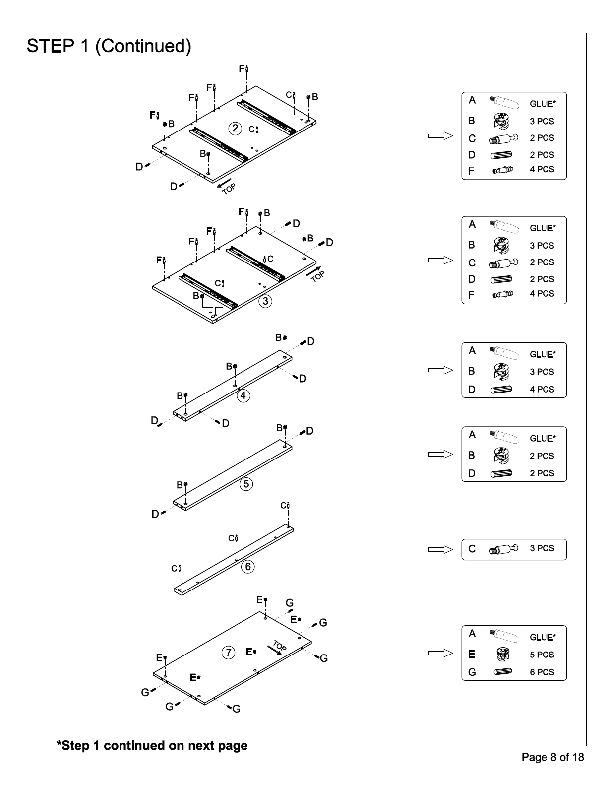
*NOTE:
Apply
a small amount
of
(A) Glue
to
(D/G) Large/Small Wood Dowels before placing them in
the corresponding holes as shown.
5.
Insert (D) Large Wood Dowels into the corresponding holes on Panels 2,
3,
4 and
5
as shown.
6.
Insert (G) Small Wood Dowels into the corresponding holes on Panels
7,
8,
11
(x2),
12
(x2) and 15 (x2) as
shown.
1.
Install (C) Large Cam Screws into the pre-threaded plastic bushings as shown on Panels
1,
2, 3
and
6
as
shown. FULLY TIGHTEN using
a
Phillips Head Screwdriver.
2.
Install (F) Small Cam Screws into the corresponding holes as shown on Panels
1,
2, 3,
9,
10
and
13
(x2).
FULLY TIGHTEN using
a
Phillips Head Screwdriver.
3.
Next, insert (B) Large Cam Locks into the corresponding holes on Panels
2, 3,
4 and
5.
*NOTE: Refer to the Cam Lock/Dowel Placement Supplement below
for
additional detail on (B) Large
Cam Lock placement.
4. Next, insert (E) Small Cam Locks into the corresponding holes on Panels
7,
8,
11
(x2),
12
(x2) and
15
(x2)
as shown.
3
STEP
1
-
PRE-ASSEMBLY
ASSEMBLY INSTRUCTION
FRONT
1