Zahl AIRCOM User manual

Rev.7a (for units from ser.no. 51053/built 2010) 26.01.2010 This document substitutes previous versions page 1 of 34
Zähl Elektronik-Tontechnik • Odenthaler Str. 47 • D-51465 Bergisch Gladbach • [email protected] • www.zaehl.com
Distributor (National/International):
sono Studiotechnik GmbH • Haagerstraße 5 • D-81671 München • Tel. +49 89 419671-0 • [email protected] • www.sono.de
AIRCOM Manual
from ser.no. 51053/built 2010
AIRCOM
Dual Commentator’s Unit
•high level of functionality
• sophisticated configuration, also
applicable as interpreter unit
• easy handling
•compact design
•reliable in operation
•versatile link features
AIRCOM provides ON-AIR and Intercom functionality for two commentators featuring great audio
performance and a high level of functionality.
AIRCOM is designed for the use with reportage- und SNG-units, for mobile broadcast setups and
studio applications.
Use AIRCOM’s comprehensive configuration and remote control features and just work your way – on
whatever demanding application: commentator, interpreter* or voice-over.
(*AIRCOM-IR Interpreter Remote unit available as optional accessory)
Straight forward analogue design with clear and intuitive handling - highly appreciated by every
operator. Furthermore, AIRCOM’s versatile link features make it easy to integrate into latest broadcast
technology.
A cover on the front panel hides switches and
trimmer potentiometers which are used for
setting up the unit. When closed after
configuration, easy handling and safe
operation are guaranteed.
standard audio I/O as XLR
37pole Sub-D with GPI I/O und audio I/O
for linking with other system components
like intercom-systems, failsafe transmission
lines etc.

Rev.7a (for units from ser.no. 51053/built 2010) 26.01.2010 This document substitutes previous versions page 2 of 34
Zähl Elektronik-Tontechnik • Odenthaler Str. 47 • D-51465 Bergisch Gladbach • [email protected] • www.zaehl.com
Distributor (National/International):
sono Studiotechnik GmbH • Haagerstraße 5 • D-81671 München • Tel. +49 89 419671-0 • [email protected] • www.sono.de
AIRCOM Manual

Rev.7a (for units from ser.no. 51053/built 2010) 26.01.2010 This document substitutes previous versions page 3 of 34
Zähl Elektronik-Tontechnik • Odenthaler Str. 47 • D-51465 Bergisch Gladbach • [email protected] • www.zaehl.com
Distributor (National/International):
sono Studiotechnik GmbH • Haagerstraße 5 • D-81671 München • Tel. +49 89 419671-0 • [email protected] • www.sono.de
AIRCOM Manual
Contents
1. Important Notes and Safety Instructions................................................................. 4
2. Scope of Delivery ...................................................................................................... 5
3. Connection ................................................................................................................ 6
3.1. Power Supply................................................................................................................................6
3.2. Audio ...........................................................................................................................................6
3.3. Control ports REMOTE GPI ............................................................................................................7
3.4. Lamp Supply/USB .........................................................................................................................7
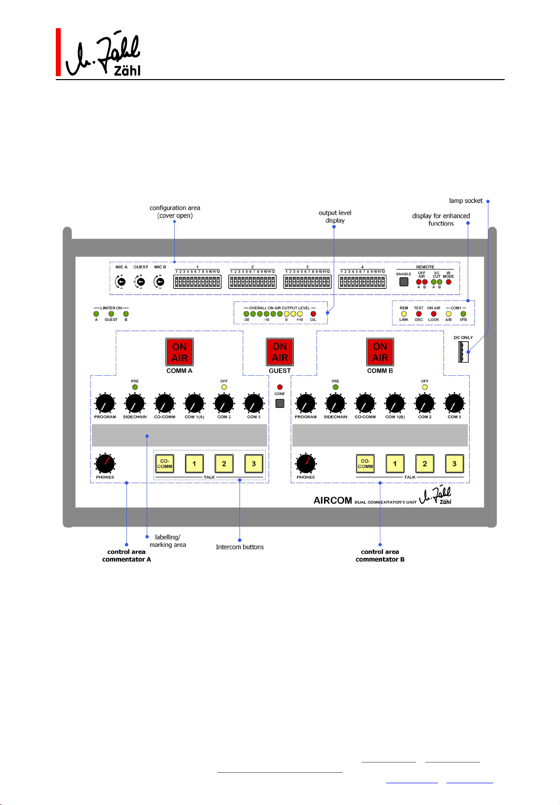
4. Front Panel Overview................................................................................................ 8
5. Basic Functions ......................................................................................................... 9
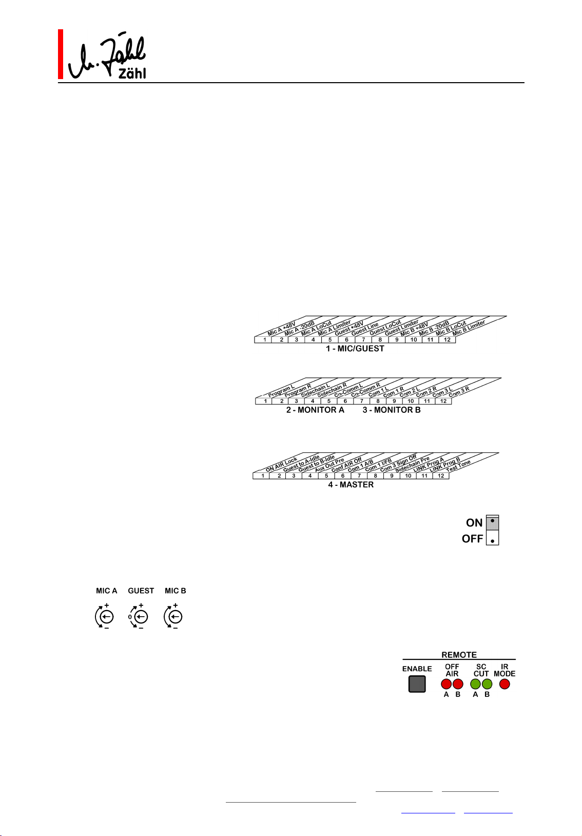
5.1. Configuration................................................................................................................................9
5.2. Commentator Channels A and B...................................................................................................10
5.3. Commentator/Interview Channel GUEST ...................................................................................... 12
5.4. Channels A+Guest+B Sum Output ............................................................................................... 13
5.5. Level Meter und O/L-Display........................................................................................................ 13
5.6. Monitoring .................................................................................................................................. 14
5.6.1. Internal Sources ....................................................................................................................................... 14
5.6.2. External Sources ...................................................................................................................................... 14
5.6.3. Intercom Call Signalisation ........................................................................................................................ 14
5.6.4. L-R Monitoring Options / Phones Output .................................................................................................... 15
5.6.5. CONFERENCE........................................................................................................................................... 15
6. Enhanced Function.................................................................................................. 16
6.1. On Air Lock................................................................................................................................. 16
6.2. Guest To Idle A / Guest To Idle B ................................................................................................ 16
6.3. Aux Out Pre................................................................................................................................ 16
6.4. Conference Air Off ...................................................................................................................... 16
6.5. COM 1 A/B ................................................................................................................................. 17
6.6. COM 1 IF/B ................................................................................................................................ 17
6.7. COM 3 Signalisation Off............................................................................................................... 17
6.8. Sidechain Pre.............................................................................................................................. 18
6.9. Link Program A / Link Program B .................................................................................................18
6.10. Test Oscillator............................................................................................................................. 19
6.11. Guest Lock ................................................................................................................................. 19
6.12. IR Mode (Interpreter Mode)..................................................................................................... 20
7. REMOTE................................................................................................................... 21
7.1. Audio I/O ................................................................................................................................... 21
7.2. Operational Elements and Functional Displays .............................................................................. 21
7.3. Control I/O - GPI I/O .................................................................................................................. 22
7.4. Examples of Use ......................................................................................................................... 23
7.4.1. Simple Intercom Link ................................................................................................................................ 23
7.4.2. Intercom and Commentator Audio Link including fail-safe operation ............................................................ 25
8. Block Diagrams ....................................................................................................... 26
9. Connectors/Pin-Out................................................................................................ 30
10. Technical Data......................................................................................................... 32
11. Measures and Weights............................................................................................ 34

Rev.7a (for units from ser.no. 51053/built 2010) 26.01.2010 This document substitutes previous versions page 4 of 34
Zähl Elektronik-Tontechnik • Odenthaler Str. 47 • D-51465 Bergisch Gladbach • [email protected] • www.zaehl.com
Distributor (National/International):
sono Studiotechnik GmbH • Haagerstraße 5 • D-81671 München • Tel. +49 89 419671-0 • [email protected] • www.sono.de
AIRCOM Manual
1. Important Notes and Safety Instructions
Before unpacking and operating the equipment read these Notes and Safety Instructions carefully.
More notes and instructions can be found in the following chapters of this manual. Follow all notes and
instructions.
The term „equipment“ stands for the AIRCOM unit as well as the provided power supply.
1.1. The equipment must only be used for the purpose described in this manual.
1.2. Keep the manual for further reference. When passing the equipment on, enclose the manual.
1.3. Do not operate the equipment at
-very high air humidity (>85% relative humidity)
-high ambient temperature (>40°C) or in the vicinity of heat radiating equipment or objects
-places which are exposed to solar radiation
-at very low temperatures (<5°C)
1.4. Ensure appropriate air ventilation.
1.5. Do not block the ventilation slots of the equipment. Keep free a minimum of 20mm around the
equipment.
1.6. Do not store the equipment at temperatures below -20°C or above +50°C.
1.7. Do never expose the equipment to environmental conditions which can lead to the incidence of
condensation water.
1.8. Do not expose the equipment to mechanical stress or shock.
1.9. Ensure that liquids cannot get into the equipment.
1.10. Ensure that foreign objects cannot get into the equipment.
1.11. Only clean the equipment with smooth cleaning tissues and soft detergents.
1.12. Never open the equipment.
1.13. Only operate the unit with the provided power supply. When operating with other power supplies,
warranty will be void.
1.14. In case the equipment has been dropped or there is any external or functional damage, do not continue
to operate the equipment. Have the equipment checked at your dealer’s workshop or a person who is
qualified to do such checks.
1.15. Only connect the equipment to a legally approved, earthed, mains power supply.
1.16. In case of any damage of mains cable or power supply there is the risk of a perilous electrical shock!
Replace the mains cable immediately. Have the power supply checked or replace it. Regularly check
mains cable and power supply for any damage.
1.17. When shipping, use a package which protects the equipment from environmental impact such as
mechanical shock or humidity.
1.18. The equipment applies to EU directives RoHS and WEEE. Disposal has to be carried out according to
WEEE. As this equipment is classified as professional equipment for industrial use (B2B), manufacturer
and purchaser conclude the following agreement: According to ElektroG §10 Abs. 2 Satz 3 (ref. to
German/EU law) the manufacturer takes over the disposal if the purchaser sends back the equipment at
his own expense. Alternatively the purchaser disposes of the equipment according to WEEE at his own
expense. In case the purchaser passes on or sells the equipment, this agreement has to be passed on.
Manufacturer WEEE register number: DE 90586269

Rev.7a (for units from ser.no. 51053/built 2010) 26.01.2010 This document substitutes previous versions page 5 of 34
Zähl Elektronik-Tontechnik • Odenthaler Str. 47 • D-51465 Bergisch Gladbach • [email protected] • www.zaehl.com
Distributor (National/International):
sono Studiotechnik GmbH • Haagerstraße 5 • D-81671 München • Tel. +49 89 419671-0 • [email protected] • www.sono.de
AIRCOM Manual
1.19. Manufacturer’s warranty covers the equipment to be free from defects of quality at the time of delivery
for a period of 24 month presumed that
-the equipment was treated properly according to its intended use
-all information and safety instructions given in this manual have been followed
-the equipment shows no external damage
-the equipment is shipped to the manufacturer or to an authorised repair-shop free of charge
-a proof of purchase is supplied
-a detailed failure description is supplied
The manufacturer takes over cost of parts and labour incurred by repair.
Any other costs including shipping and packaging will be charged.
1.20. We expressly exclude any liability for incidental or consequential damages which might arise from
operating the equipment, including failure of the equipment.
1.21. All information in this manual has been carefully reviewed. It has been updated at the time of passing
for press. Nevertheless we do not take over any liability for sufficiency or errors.
1.22. EC Declaration of Conformity: The equipment applies to applicable EMC rules 2004/108/EC.
2. Scope of Delivery
2.1. Unit AIRCOM
2.2. Power Supply
2.3. Mains Cable (not for all countries)
2.4. Manual

Rev.7a (for units from ser.no. 51053/built 2010) 26.01.2010 This document substitutes previous versions page 6 of 34
Zähl Elektronik-Tontechnik • Odenthaler Str. 47 • D-51465 Bergisch Gladbach • [email protected] • www.zaehl.com
Distributor (National/International):
sono Studiotechnik GmbH • Haagerstraße 5 • D-81671 München • Tel. +49 89 419671-0 • [email protected] • www.sono.de
AIRCOM Manual
3. Connection
3.1. Power Supply
3.1.1. Plug the 4pole XLR connector which is mounted to the cable fixed to the power supply into one of the
4pole XLR connectors designated “POWER IN” on the rear panel of the AIRCOM unit.
3.1.2. Connect the power supply to a correctly earthed mains power socket. You may connect the power
supply to 100-240VAC at 47-63Hz mains voltage without the need of selecting a voltage range.
Important Note: Always connect the power supply in the order described above. Otherwise there is a
risk of damaging the power supply and/or the unit.
3.1.3. AIRCOM units provide two power inputs. You can connect two power supplies at the same time in order
to ensure a fail-safe operation. If power at one of the inputs fails, the other one will take over.
3.1.4. 12V-24V regulated DC is allowed at the power inputs. We deliver power supplies within this voltage
range. You can connect power supplies with differing voltages at the same time. The one with the
higher voltage supplies the unit. If it fails, the one with the lower voltage will take over.
3.2. Audio
3.2.1. Microphone Inputs
Microphone inputs are designed for input levels from -64dBu to 0dBu (GUEST: -60dBu...-15dBu).
Depending on the configuration setting the inputs provide 48V phantom power.
Important Note: Before connecting a microphone always check if the input configuration on your
AIRCOM complies with the microphone data. In case of incompatibility there is a risk of damaging your
microphone.
3.2.2. Headphones Outputs
Only connect stereo-wired jack connectors on the headphones outputs. AIRCOM provides dedicated
output circuits for left and right channel. Do not connect Tip and Ring on a stereo jack and never use a
mono jack.
The headphones outputs deliver voltages up to 10Veff. Only connect headphones with an impedance of
more than 30 Ohms per system.
Please consider that the headphones output stages provide high gain margin in order to drive high
impedance as well as low impedance headphones. Using low impedance headphones it is most unlikely
that you need to set the PHONES volume controller to maximum position.
Important Note: Always set the phones level potentiometer labelled „PHONES“ to minimum (fully
counter-clockwise) before you connect your headphones. Otherwise there is a risk of damaging your
ears by high sound pressure level. Furthermore there is a risk of damaging your headphones.
3.2.3. Other Audio Inputs and Audio Outputs
Standard audio inputs and audio outputs are transformer balanced and designed to a reference level of
+6dBu and a maximum level of +18dBu (typ.).
Auxiliary audio inputs/outputs and GUEST line input are designed as electronically balanced stages at the
same reference level and maximum level as above.
Important Note: Connecting DC exceeding 1V is not allowed and can lead to damages inside the unit.

Rev.7a (for units from ser.no. 51053/built 2010) 26.01.2010 This document substitutes previous versions page 7 of 34
Zähl Elektronik-Tontechnik • Odenthaler Str. 47 • D-51465 Bergisch Gladbach • [email protected] • www.zaehl.com
Distributor (National/International):
sono Studiotechnik GmbH • Haagerstraße 5 • D-81671 München • Tel. +49 89 419671-0 • [email protected] • www.sono.de
AIRCOM Manual
3.3. Control ports REMOTE GPI
All control outputs are designed to be interfaced with 5V logic circuitry.
Important Note: Connect DC in the 0-5V range to the control inputs only. Control outputs may only be
connected to circuits which operate in the 0-5V DC range. Never connect any supply voltage directly to a
control output. Refer to chapter „Technical Data“ to find information about maximum allowable current.
Exceeding any limits can cause damage on the unit or the circuitry you connect.
Refer to chapter „Technical Data“ for more details about circuitry and connection.
3.4. Lamp Supply/USB
Right hand on the front panel there is a USB Type A socket designated “DC ONLY”. It serves exclusively
for supplying a standard 5V LED Lamp with USB connector (commercially available with gooseneck).
Important Note: Never connect any other equipment. Especially never connect a PC or PC peripheral
equipment to this USB socket. There is the danger of damage to your AIRCOM as well as the connected
equipment.
More details about technical data, functions and connector pin-outs are specified in the following
chapters of this manual.

Rev.7a (for units from ser.no. 51053/built 2010) 26.01.2010 This document substitutes previous versions page 8 of 34
Zähl Elektronik-Tontechnik • Odenthaler Str. 47 • D-51465 Bergisch Gladbach • [email protected] • www.zaehl.com
Distributor (National/International):
sono Studiotechnik GmbH • Haagerstraße 5 • D-81671 München • Tel. +49 89 419671-0 • [email protected] • www.sono.de
AIRCOM Manual
4. Front Panel Overview

Rev.7a (for units from ser.no. 51053/built 2010) 26.01.2010 This document substitutes previous versions page 9 of 34
Zähl Elektronik-Tontechnik • Odenthaler Str. 47 • D-51465 Bergisch Gladbach • [email protected] • www.zaehl.com
Distributor (National/International):
sono Studiotechnik GmbH • Haagerstraße 5 • D-81671 München • Tel. +49 89 419671-0 • [email protected] • www.sono.de
AIRCOM Manual
5. Basic Functions
This chapter is dedicated to basic functions only. When you work with AIRCOM for the first time, we
recommend to study this chapter step by step.
Before you start, please set all volume controls to minimum (counter-clockwise position).
Enhanced functionality and comprehensive configuration are described in the following chapters.
5.1. Configuration
All configuration elements are accessible on the front panel, normally hidden behind a cover. For access
loosen the two knurled head screws on the left and right end of the cover and flap it up.
There are four configuration banks, numbered from left to right, each consisting of 12 miniature rocker
switches. All switch functions are labelled in short form on the inside of the cover.
In this manual the switches are designated by bank number followed by the switch number, eg. 1-11
(bank 1, switch 11) or 4-2 (bank 4, switch 2).
Bank 1, designated MIC/GUEST,
provides basic settings of the
commentator channels.
Bank 2, designated MONITOR A,
provides monitoring options for
commentator A,
Bank 3, designated MONITOR B,
(the same) monitoring options for
commentator B.
Bank 4, designated MASTER,
provides special functions like
operational options, remote/link
options or test oscillator activation.
The rocker switches are off, when they are actuated to the lower position; they are on,
when they are actuated to the upper position.
When you get started with AIRCOM and this manual, we assume that all configuration
switches are in the off position.
On the left there are 3 configuration trimmer potentiometers. Normal working
position complies to the shown arrow position. In this manual the trimmers are
designated „Gain Trimmers“ with the affix MIC A, MIC B or GUEST.
On the right there are configuration elements for remote/link operation,
a latching push button switch labelled „Remote Enable“ and 5 LED-
displays. Before you go on, please make sure that the switch is in the
idle (not depressed) position.

Rev.7a (for units from ser.no. 51053/built 2010) 26.01.2010 This document substitutes previous versions page 10 of 34
Zähl Elektronik-Tontechnik • Odenthaler Str. 47 • D-51465 Bergisch Gladbach • [email protected] • www.zaehl.com
Distributor (National/International):
sono Studiotechnik GmbH • Haagerstraße 5 • D-81671 München • Tel. +49 89 419671-0 • [email protected] • www.sono.de
AIRCOM Manual
5.2. Commentator Channels A and B
5.2.1. Inputs and Configuration
Microphone inputs, XLR 3pole connectors labelled „MIC A“ and „MIC B“, are located on the rear panel.
Prior to connecting a microphone use configuration bank 1 in order to perform an input configuration
appropriate to your microphone.
Setting a switch to the ON position will activate the described function.
Function MIC A MIC B
Phantom power +48V 1-1 1-9
- 20dB Pad 1-2 1-10
LoCut 80Hz 24dB/Oct. 1-3 1-11
Limiter 1-4 1-12
Phantom power: Only choose this option for microphones which are designed for operation
with 48V-phantom power. Otherwise there is a risk of damage to your
microphone.
- 20dB Pad: Just in case you expect very high microphone levels. Also refer to section
“Gain Setting” (see below).
LoCut 80Hz 24dB/Oct.: Frequencies below 80Hz are suppressed very effectively. Use depends on
speaker, microphone and environmental conditions. LoCut will also reduce
“pop noises” or low frequency interference caused by air condition systems.
Limiter: Output level is limited to reference level. If selected, a green LED (LIMITER
ON) will light up on the front panel.
Note: Limiter configuration setting only affects the commentator channel
outputs. Intercom outputs are always post limiter.
Gain Setting
Set microphone gain at the gain trimmers labelled “MIC A” and “MIC B” on the front panel, left hand in
the configuration area. Always set gain with limiter off.
You can use the OVERALL ON AIR OUTPUT LEVEL to control your gain setting, if the respective ON AIR
button is activated. The O/L (Overload) LED at the right end of the display lights up if there is the
danger of signal clipping (1-2 dB below clipping), also refer to chapter 5.5.
In case your setting is fine with gain trimmer near its minimum (counter clockwise) and -20dB Pad OFF,
please consider:
Best S/N ratio is assumed with this setting. But if you expect high unpredictable levels, i.e. you need
maximum headroom, you should switch -20dB Pad to the ON position and on the other hand rise the
gain setting.
Limiter function
If a channel signal level exceeds reference level, the signal is controlled by the integrated limiter circuit
at the output (As the limiter provides a soft-knee technique, in fact signals somewhat below reference
level are controlled as well.). There is internal headroom of approximately 18dB before limiter.
Gain setting with Limiter
As described above, the limiter will to a certain amount affect levels below limiter threshold. If you set
gain with limiter activated referring to the “0” LED on the level meter, you give away some headroom.
So always set gain with limiter OFF, then switch it ON.
Please consider that a too high gain setting in combination with a limiter can lead to a loss of speech
comprehensibility. E.g. background noise may be audible in speech intervals.

Rev.7a (for units from ser.no. 51053/built 2010) 26.01.2010 This document substitutes previous versions page 11 of 34
Zähl Elektronik-Tontechnik • Odenthaler Str. 47 • D-51465 Bergisch Gladbach • [email protected] • www.zaehl.com
Distributor (National/International):
sono Studiotechnik GmbH • Haagerstraße 5 • D-81671 München • Tel. +49 89 419671-0 • [email protected] • www.sono.de
AIRCOM Manual
Note: Usually the limiter serves to suppress unattended high level peaks, which often occurs at on-site
broadcast service. In case you use AIRCOM in a studio like environment, it might be more reasonable to
switch off the limiter and leave the whole signal processing to a sound engineer on a mixing desk.
5.2.2. ON AIR Buttons and Channel A/B Outputs
In basic configuration the ON AIR buttons are not active, when the unit is powered up. In this state they
light up yellow. Push them once to activate, they light up red. Push them again to deactivate.
Activating ON AIR button COMM A resp. COMM B switches the commentator’s microphone signals to the
respective output. The outputs, 3pole XLR connectors, are located on the rear panel, designated OUT A
and OUT B.
5.2.3. TALK buttons and Intercom Outputs
TALK buttons have a „momentary“ switch action: They are active, as long as you keep them depressed.
In the active state they light up red, in the deactivated state there is no lighting.
When a TALK button is active, ON AIR will be deactivated for the respective Commentator.
You can address four Intercom destinations:
Button 1: COM1 output, XLR 3pole connector on the rear panel designated COM1 OUT
Button 2: COM2 output, XLR 3pole connector on the rear panel designated COM2 OUT
Button 3: COM3 output, XLR 3pole connector on the rear panel designated COM3 OUT
Button CO-COMM: Co-Commentator on the same AIRCOM-Unit.
Note: As mentioned above, always post limiter signal is used for the Intercom outputs.

Rev.7a (for units from ser.no. 51053/built 2010) 26.01.2010 This document substitutes previous versions page 12 of 34
Zähl Elektronik-Tontechnik • Odenthaler Str. 47 • D-51465 Bergisch Gladbach • [email protected] • www.zaehl.com
Distributor (National/International):
sono Studiotechnik GmbH • Haagerstraße 5 • D-81671 München • Tel. +49 89 419671-0 • [email protected] • www.sono.de
AIRCOM Manual
5.3. Commentator/Interview Channel GUEST
This channel is dedicated for a guest commentator or interview partner, as well as for feeding an
auxiliary line signal into the unit. Hence it provides both, microphone and line input circuitry.
There are no intercom facilities in the GUEST Channel.
5.3.1. Input and Configuration
Microphone input, XLR 3pole connectors labelled „MIC GUEST“, is located on the rear panel.
Prior to connecting a microphone use configuration bank 1 in order to perform an input configuration
appropriate to your microphone or other audio device.
Setting a switch to the ON position will activate the described function.
Function switch comment
Phantom power +48V 1-5*
Line input 1-6*
* in case 1-6 is on, 1-5 will be
automatically off
LoCut 80Hz 24dB/Oct. 1-7
Limiter 1-8
Phantom power: Only choose this option for microphones which are designed for operation
with 48V-phantom power. Otherwise there is a risk of damage to your
microphone.
Line input: Switch-over to an electronically balanced line input stage
LoCut 80Hz 24dB/Oct.: Frequencies below 80Hz are suppressed very effectively. Use depends on
speaker, microphone and environmental conditions. LoCut will also reduce
“pop” or low frequency interference caused by air condition systems.
Limiter: Output level is limited to reference level. If selected, a green LED (LIMITER
ON) will light up on the front panel.
Gain Setting
Set microphone gain at the gain trimmer labelled “MIC GUEST” on the front panel, left hand in the
configuration area. Always set gain with limiter off.
In opposite to the others, the scale of gain trimmer “MIC GUEST” provides a “0”- reference point. This
marking is relevant only in case “Line Input” is selected: If the trimmer is set to this point, input gain is
0dB +/-1dB. Gain range of GUEST Line Input is -6dB … +20dB.
You can use the OVERALL ON AIR OUTPUT LEVEL to control your gain setting, if the ON AIR button
GUEST is activated. The O/L (Overload) LED at the right end of the display lights up if there is the
danger of signal clipping (1-2 dB below clipping), also refer to chapter 5.5.
Limiter function
Please refer to passage “Limiter function” in chapter 5.2.1.
5.3.2. ON AIR Button and Channel GUEST Output
In basic configuration the ON AIR button is not active, when the unit is powered up. In this state it lights
up yellow. Push it once to activate, it lights up red. Push it again to deactivate.
Activating ON AIR button GUEST switches the commentator’s microphone signal to the output. The
output, a 3pole XLR connector, is located on the rear panel, designated OUT GUEST.
Note: Also refer to GUEST LOCK, chapter 6.11

Rev.7a (for units from ser.no. 51053/built 2010) 26.01.2010 This document substitutes previous versions page 13 of 34
Zähl Elektronik-Tontechnik • Odenthaler Str. 47 • D-51465 Bergisch Gladbach • [email protected] • www.zaehl.com
Distributor (National/International):
sono Studiotechnik GmbH • Haagerstraße 5 • D-81671 München • Tel. +49 89 419671-0 • [email protected] • www.sono.de
AIRCOM Manual
5.4. Channels A+Guest+B Sum Output
The audio sum of channels A, B and GUEST (-3dB summing) can be helpful in cases which do not
require single commentator output lines. The output, 3pole XLR, is located on the rear panel labelled
OUT A+GUEST+B.
5.5. Level Meter und O/L-Display
Level Meter
The 9-LED display OVERALL ON AIR OUTPUT LEVEL with approximate PPM characteristic records all
output signals post ON AIR button. It shows the peak level of the output with the highest level, not the
summed output level.
Note 1: When adjusting microphone gain you might use the level meter as a reference. As the meter is
fed by post ON AIR button signal, just switch the respective channel ON AIR which you want to adjust.
Note 2: For line checks you can switch the built in test oscillator on the outputs. The oscillator is applied
straight to the output stage and will not be recorded by the level meter. Instead the level meter will
show the microphone signal even when the oscillator is on.
O/L- (Overload-) Display
The bright red LED right hand of the level meter alerts you of high level overload. It will light up 1-2 dB
below clipping level. Even very short overloads are displayed for at least one second, so you will not
miss it.
The circuitry records all three channels, A, B and Guest, post the input amplifiers. As with the level
meter, only the highest level of the three is evaluated.
The reason for using the post input amplifier signal is that level might be reduced by LoCut and Limiter.
So evaluating the level at the output would not make sure that every overload is detected.
Thus the overload display will light up even if the respective channel is not ON AIR active.
Furthermore the circuitry evaluates if the limiter is on or off. As there is 6dB more headroom when the
limiter is on, the LED will in this case light up at an input level 6 dB higher.

Rev.7a (for units from ser.no. 51053/built 2010) 26.01.2010 This document substitutes previous versions page 14 of 34
Zähl Elektronik-Tontechnik • Odenthaler Str. 47 • D-51465 Bergisch Gladbach • [email protected] • www.zaehl.com
Distributor (National/International):
sono Studiotechnik GmbH • Haagerstraße 5 • D-81671 München • Tel. +49 89 419671-0 • [email protected] • www.sono.de
AIRCOM Manual
5.6. Monitoring
Commentator A and B only, GUEST has no monitoring facilities.
Each monitoring section provides 6 audio sources with individual level controls and a phones level
control as a master.
4 sources are external: Program and Intercom inputs.
2 are internal: Local commentators A and B.
5.6.1. Internal Sources
SIDECHAIN: The commentator’s own microphone signal pre limiter, i.e. channel A for commentator A
and channel B for commentator B. The signal is present only, when a commentator is „active“ an output,
i.e. if ON AIR button is active or a TALK button is depressed *.
CO-COMM: The co-commentator’s microphone signal pre limiter, i.e. channel B for commentator A and
channel A for commentator B. The signal is present only, if the co-commentator is ON AIR or holds the
CO-COMM intercom button depressed **.
* different behaviour if CONFERENCE is activated (refer to 5.6.5) or if SIDECHAIN PRE is on by
configuration (refer to 6.8)
* different behaviour if CONFERENCE is activated (refer to 5.6.5)
5.6.2. External Sources
PROGRAM: Program signal, fed into 3pole XLR labelled PROGRAM on rear panel.
COM 1: Intercom signal, fed into 3pole XLR labelled COM1 on rear panel.
COM 2: Intercom signal, fed into 3pole XLR labelled COM2 on rear panel.
COM 3: Intercom signal, fed into 3pole XLR labelled COM3 on rear panel.
5.6.3. Intercom Call Signalisation
Incoming audio signals at COM1, COM2 and COM3 are signalised at the respective TALK buttons 1, 2
and 3. Signalisation appears at commentator A and commentator B at the same time *.
* different behaviour by configuration refer to 6.5 und 6.7
A TALK button lights up yellow, when the incoming signal level is higher than approx. -20dB.
Signalisation is stored for approx. 8 seconds, so that even a short signal is clearly indicated.
When a TALK button is depressed, signalisation will go off immediately.
When a TALK button is depressed while there is an incoming signal triggering the signalisation, the TALK
button lights up orange. In this case signalisation is not stored, thus the orange colour follows the
incoming modulation.
Basically the CO-COMM buttons provide the same signalling function, but they do not depend on audio
modulation. They are triggered when the co-commentator presses his CO-COMM button. The
signalisation is not stored, it is only active as long as the co-commentator holds his CO-COMM button
depressed.

Rev.7a (for units from ser.no. 51053/built 2010) 26.01.2010 This document substitutes previous versions page 15 of 34
Zähl Elektronik-Tontechnik • Odenthaler Str. 47 • D-51465 Bergisch Gladbach • [email protected] • www.zaehl.com
Distributor (National/International):
sono Studiotechnik GmbH • Haagerstraße 5 • D-81671 München • Tel. +49 89 419671-0 • [email protected] • www.sono.de
AIRCOM Manual
5.6.4. L-R Monitoring Options / Phones Output
Each monitoring source can be configured individually for commentator A or B to appear left, right or
center at the phones output.
Perform this setting at configuration banks 2 and 3. A record in the chart below stands for the respective
switch in the ON position.
Commentator A
Commentator B
The monitoring mix is fed to the master level control labelled PHONES. Phones outputs are available on
the rear panel as 6,3mm stereo jack sockets designated PHONES A and PHONES B.
* differing behaviour if REMOTE/LINK is active, refer to 6.9
5.6.5. CONFERENCE
The CONFERENCE button (labelled CONF) and the associated LED are located on the front panel in
between the monitor level controls of commentator A and commentator B.
After powering up the unit, CONFERENCE is not active. Push the button once to activate, push it again
to deactivate.
When activated, the commentators can listen to their own microphone signal as well as their co-
commentator’s microphone signal irrespective of any ON AIR or TALK function being active or not.
Example of use: During a show break the commentators can talk to each other without taking their
headphones off (which could lead to missing important intercom messages).
Note: additional configuration: CONF AIR OFF Function, refer to 6.4
source left right center
Program 2-1 2-2 none* or both
Sidechain 2-3 2-4 none or both
Co-Comm 2-5 2-6 none or both
Com 1 2-7 2-8 none or both
Com 2 2-9 2-10 none or both
Com 3 2-11 2-12 none or both
source left right mittig
Program 3-1 3-2 none* or both
Sidechain 3-3 3-4 none or both
Co-Comm 3-5 3-6 none or both
Com 1 3-7 3-8 none or both
Com 2 3-9 3-10 none or both
Com 3 3-11 3-12 none or both

Rev.7a (for units from ser.no. 51053/built 2010) 26.01.2010 This document substitutes previous versions page 16 of 34
Zähl Elektronik-Tontechnik • Odenthaler Str. 47 • D-51465 Bergisch Gladbach • [email protected] • www.zaehl.com
Distributor (National/International):
sono Studiotechnik GmbH • Haagerstraße 5 • D-81671 München • Tel. +49 89 419671-0 • [email protected] • www.sono.de
AIRCOM Manual
6. Enhanced Function
6.1. On Air Lock
▪Configuration switch 4-1
▪LED labelled ON AIR LOCK lights up red, located in the „display for enhanced funtions“ area on the
front panel
In ON AIR LOCK mode all ON AIR buttons are normally active. To deactivate keep the buttons depressed
- use them as a “cough-button”.
6.2. Guest To Idle A / Guest To Idle B
▪Configuration switch 4-2 for commentator A
▪Configuration switch 4-3 for commentator B
Example of use: You want to feed a signal (e.g. ambience sound) into the commentator’s channels when
they are not ON AIR active.
Connect a signal source to input GUEST. Switch GUEST ON AIR active.
GUEST signal will now appear at commentator A output resp. commentator B output when they are not
ON AIR active.
Note: This mode does not affect the normal behaviour of the GUEST channel. GUEST signal will be
present at GUEST output and it will be indicated by the level meter.
6.3. Aux Out Pre
▪Configuration switch 4-4
Audio outputs AUX OUT A and AUX OUT B are available at the Sub-D connector designated REMOTE
GPI/AUDIO on the rear panel.
AUX OUT A provides commentator A signal, AUX OUT B commentator B signal. The outputs follow the
LIMITER configuration set for the respective channels.
In AUX OUT PRE mode, commentator signals are always present, independent of ON AIR state or any
TALK function being active.
Normally, i.e. switch 4-4 OFF, commentator signal is only present, if either the respective commentator’s
ON AIR button or a TALK function is active.
Note 1: Using this function, inform the commentators about the fact, that other people can listen to
what they say, even if there is no operational button active on the AIRCOM front panel.
Note 2: In most cases you will use this function when linking the AIRCOM unit to other system
components. Find more information about linking features in chapter 7.
6.4. Conference Air Off
▪Configuration switch 4-5
Practical Example: Both commentators A and B are OFF AIR, e.g. during a show break. They activate
CONFERENCE, so they can talk to each other without taking their headphones off.
In CONFERENCE AIR OFF mode, CONFERENCE will automatically be deactivated as soon as one of them
switches an ON AIR button active (Precondition: Both have been OFF AIR before.).
Still they have the possibility to activate CONFERENCE by pushing the CONFERENCE button at any time.
Note: This option prevents irritations in case commentators miss to switch off CONFERENCE after a
show break.

Rev.7a (for units from ser.no. 51053/built 2010) 26.01.2010 This document substitutes previous versions page 17 of 34
Zähl Elektronik-Tontechnik • Odenthaler Str. 47 • D-51465 Bergisch Gladbach • [email protected] • www.zaehl.com
Distributor (National/International):
sono Studiotechnik GmbH • Haagerstraße 5 • D-81671 München • Tel. +49 89 419671-0 • [email protected] • www.sono.de
AIRCOM Manual
6.5. COM 1 A/B
▪Configuration switch 4-6
▪LED labelled COM1 A/B lights up yellow, located in the „display for enhanced funtions“ area on the
front panel
COM1 switches to 2-channel mode on the input, while the output will work as usual. COM2 is
deactivated completely.
Commentators A and B can be addressed separately and signalisation on the TALK 1 buttons will also
only light up at the respective commentator’s operation area.
Pushing TALK 1 buttons will result in both commentators signals will appear as usual at COM1 output.
The alternative labelling in brackets - front and rear panel - are intended for this mode:
XLR input COM1 ÆCOM1A
XLR input COM2 ÆCOM1B
Level control COM1 in Commentator A operation area ÆCOM1A
Level control COM1 in Commentator B operation area ÆCOM1B
All operational controls for COM2 are deactivated which is signalled by the LEDs above the COM2 level
controls. Both LEDs, labelled OFF, light up yellow. Signalisation at TALK 2 buttons is suppressed and the
respective control outputs (GPI, refer to 7.3) are deactivated.
Feed an incoming intercom signal for commentator A to input COM1A and the respective signal for
commentator B to input COM1B.
COM1A signal will appear at the level control COM1A and will only be signalised at TALK 1 button of
commentator A.
COM1B signal will appear at the level control COM1B and will only be signalised at TALK 1 button of
commentator B.
COM3 is not affected by COM1 A/B mode.
6.6. COM 1 IF/B
▪Configuration switch 4-7
▪LED labelled COM1 IF/B lights up green, located at the „display for enhanced funtions“ area on the
front panel
In COM IF/B mode COM1 has priority in the monitor section. When there is audio modulation (same
level threshold as implemented for signalisation) at COM1 input, all other monitor sources are dimmed
by about 9dB. So any announcement on COM1 will be clearly emphasized.
In case COM1 A/B is selected, COM1 IF/B will work independently on the A and B channel.
6.7. COM 3 Signalisation Off
▪Configuration switch 4-8
In case you want to use COM3 as a second program input, signalisation at TALK 3 button would be
disturbing. COM3 SIGNALISATION OFF mode suppressed signalisation at COM3 completely.
All other functions of COM3 are not affected.

Rev.7a (for units from ser.no. 51053/built 2010) 26.01.2010 This document substitutes previous versions page 18 of 34
Zähl Elektronik-Tontechnik • Odenthaler Str. 47 • D-51465 Bergisch Gladbach • [email protected] • www.zaehl.com
Distributor (National/International):
sono Studiotechnik GmbH • Haagerstraße 5 • D-81671 München • Tel. +49 89 419671-0 • [email protected] • www.sono.de
AIRCOM Manual
6.8. Sidechain Pre
▪Configuration switch 4-9
▪LED labelled PRE lights up green, located above the SIDECHAIN level controls
Commentators A and B monitor their own microphone signal via the SIDECHAIN level control. The
SIDECHAIN signal is normally present only, when either ON AIR button or TALK button are active, thus
giving a definite feedback, if a commentator is active to the “outside world” or not.
In SIDECHAIN PRE mode the SIDECHAIN signal is always present.
Note: SIDECHAIN PRE does not substitute CONFERENCE function. SIDECHAIN PRE is a configuration
feature, while CONFERENCE is operated during normal use on the front panel. Furthermore
CONFERENCE additionally affects the monitoring of the co-commentator.
6.9. Link Program A / Link Program B
▪Configuration switch 4-10 for commentator A
▪Configuration switch 4-11 for commentator B
Note: Typically you will use this feature when linking your AIRCOM to external components. Find more
information about link features in chapter 7.
Audio inputs AUX IN A and AUX IN B are located at the Sub-D connector on the rear panel.
In case REMOTE/LINK mode (refer to chapter 7) is selected, audio signals fed into these inputs will
substitute the program input signal. Unlike the program signal, AUX IN signals are fed post PROGRAM
level control. So PROGRAM level control in this case has no effect on the monitoring volume.
Considering the L-R MONITORING OPTIONS for the program input (configuration banks 2 and 3) there
are more options available:
Commentator A, configuration switch 4-10 ON-position, LINK/REMOTE selected
2-1 2-2 headphones monitoring
ON OFF AUX IN A left
OFF ON AUX IN A right
ON ON AUX IN A center
OFF OFF Stereo: AUX IN A left, AUX IN B right
Commentator B, configuration switch 4-11 ON-position, LINK/REMOTE selected
3-1 3-2 headphones monitoring
ON OFF AUX IN B left
OFF ON AUX IN B right
ON ON AUX IN B center
OFF OFF Stereo: AUX IN A left, AUX IN B right

Rev.7a (for units from ser.no. 51053/built 2010) 26.01.2010 This document substitutes previous versions page 19 of 34
Zähl Elektronik-Tontechnik • Odenthaler Str. 47 • D-51465 Bergisch Gladbach • [email protected] • www.zaehl.com
Distributor (National/International):
sono Studiotechnik GmbH • Haagerstraße 5 • D-81671 München • Tel. +49 89 419671-0 • [email protected] • www.sono.de
AIRCOM Manual
6.10. Test Oscillator
▪Configuration switch 4-12
▪LED labelled TEST OSC flashes bright red, located at the „display for enhanced funtions“ area on the
front panel
The built-in test oscillator (approx. 1kHz, level +6dBu +/-1dB) serves for rough line checks or line
identification.
When switching the oscillator on, test signal is always present at sum output A+GUEST+B, on all other
outputs only in case they are on, i.e. ON AIR buttons active or TALK buttons depressed.
On AUX OUT A and AUX OUT B it normally follows the ON AIR button state, but in case AUX OUT PRE
(refer to 6.3) is selected, it will be always present on both outputs.
Test signal always substitutes commentator signals.
Note 1: Test signal is directly fed into the output stages. It does not pass through any signal
procession. E.g. the summing output will always deliver the same level if A or B are ON AIR active or
not; there is no level change if LIMITER is on or off.
Note 2: Test signal is not recorded by the level meter. The level meter will always display commentator
signals.
6.11. Guest Lock
▪Enabled by activation of GPI In „GUEST LOCK“, Pin 7 of REMOTE GPI/AUDIO Connector
GUEST LOCK forces the GUEST ON AIR button to the activated state. Any action at the GUEST ON AIR
button has no effect.
Nevertheless GUEST ON AIR can be deactivated by GPI IN “OFF AIR G”.
The illumination of the ON AIR button shows the actual state. Yellow=not active, Red=ON AIR.
Note 1: A GUEST channel is often used for an ambience microphone or other signals which should be
permanently present at the output. GUEST LOCK forces the GUEST ON AIR button to ON. In case the
operator accidentally touches the button, it will have no effect.
Note 2: Unlike all other GPI Inputs GUEST LOCK is independent from REMOTE LINK mode, please also
refer to Chapter 7.2
Compatibility note:Pin 7 may only be connected to 0V at AIRCOM units built from 2010. On units
before this date, Pin 7 is connected to +5V internally!

Rev.7a (for units from ser.no. 51053/built 2010) 26.01.2010 This document substitutes previous versions page 20 of 34
Zähl Elektronik-Tontechnik • Odenthaler Str. 47 • D-51465 Bergisch Gladbach • [email protected] • www.zaehl.com
Distributor (National/International):
sono Studiotechnik GmbH • Haagerstraße 5 • D-81671 München • Tel. +49 89 419671-0 • [email protected] • www.sono.de
AIRCOM Manual
6.12. IR Mode (Interpreter Mode)
▪Enabled by activation of GPI In „IR Mode“, Pin 8 of REMOTE GPI/AUDIO Connector
▪LED labelled IR MODE lights up red, located on the front panel, right part of the configuration area
▪AIRCOM-IR Interpreter Remote unit required
In an interpreter application AIRCOM is used with only one microphone. The microphone signal has to
be switched alternately between output A and B.
When IR MODE is configured, connect the interpreter microphone and headphones to AIRCOM
Commentator A. Microphone input B is disabled. Microphone A signal is fed pre-Limiter to both channels.
Concerning microphone configuration for B channel, you can ignore the settings for phantom power,
20dB Pad and LoCut, but Limiter has to be set for both channels, A and B, if required.
AIRCOM in IR MODE is operated by our Interpreter Remote unit AIRCOM-IR.
Lever left position: A active
Lever right position: B active
Lever centre position: A and B off
Two LED displays left and right of the lever switch, designated A and B, are controlled by the AIRCOM
logic parallel to the ON AIR button displays: red=active, yellow=off.
Connect AIRCOM-IR to the 37pole Sub-D REMOTE GPI/AUDIO connector on the AIRCOM rear panel. Set
AIRCOM configuration to REMOTE ENABLE (ref. to chapter 7.2) and ON AIR LOCK (ref. to chapter 6.1).
AIRCOM-IR is pre-wired to activate IR MODE. It takes advantage of AIRCOM REMOTE LINK Mode in
combination with the OFF AIR GPI Control Inputs.
Note 1: As a standard, AIRCOM-IR is pre-wired to permanently switch GUEST channel OFF AIR. If you
need this channel when in interpreter mode, you can easily remove a jumper cable from AIRCOM-IR
Sub-D connector (refer to chapter 7, Remote, and to AIRCOM-IR documentation).
Due to integrated weights and skip-proof
rubber feet the remote unit is perfectly
suited to desktop operation.
Its small size make it a perfect hand-held
device as well. As the lever gives a clear
tactile feedback of the switch position it
can be operated without being in the
visual field of the operator.
The switch is equipped with a special low
noise mechanism.
Note 2: Do not forget to set Sidechain and Co-Comm monitor level controls on the AIRCOM, so the
operator can hear his microphone signal when A or B is active. In case the operator prefers to listen to
his microphone signal independent of ON AIR or TALK status, select CONFERENCE (ref. to chapter 5.6.5)
to provide “pre-“ monitoring for A and B channel.
ComLink: When using IR MODE, another control option concerning TALK buttons 1-3 should be used.
Pushing a TALK button on the AIRCOM deactivates ON AIR of the respective commentator channel. As
there is only one operator in IR MODE, it is mandatory that pushing any TALK button (1-3) should
deactivate both channels, A and B.
As a standard, AIRCOM-IR is pre-wired to performed this action by using AIRCOM GPI Control logic in
combination with REMOTE LINK mode.
AIRCOM-IR units, pre-wired with this option, are labelled “ComLink” on the bottom plate.
Table of contents
Popular Recording Equipment manuals by other brands

Schmalz
Schmalz SDI operating instructions

Mastervolt
Mastervolt MasterBus PowerCombi Interface User and installation manual

Thermo Scientific
Thermo Scientific Dionex ERS 500 product manual

Talk To Me Technologies
Talk To Me Technologies zuvo 12-D quick reference

Sea Tel
Sea Tel Cobham MXP user manual

AudioSource
AudioSource AE6SW installation manual