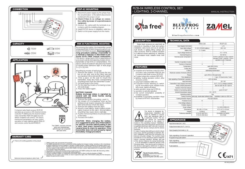
Zamel RZB-05 User manual

RZB-05 WIRELESS CONTROL SET
- UNIVERSAL MANUAL INSTRUCTION
ZAMEL Sp. z o.o.
ul. Zielona 27, 43-200 Pszczyna, Poland
tel. +48 (32) 210 46 65, fax +48 (32) 210 80 04
www.zamelcet.com, e-mail: [email protected]
VER. 003_20.05.2011
APPEARANCE
FEATURES
TECHNICAL DATA
●completesetofwirelesscontrol(2–chan-
nelremotecontrollerP-257/2and1-chan-
nelradioflushreceiverROP-01),
●lighting, heating operation control, other
receiverscontrol,
●easy installationin an electric-lighttting
or in Ø60 mm junction box,
●possibilitytousethesecondremotecon-
troller’spush-buttontocontrolotherEXTA
FREEreceivers,
●5operationmodes:switchingon,switch-
ing off, monostable mode, bistable mode,
timemode(switchoffdelay),
●wideoperationrange(upto180m),
●low current consumption, possibility of
constant operation,
●possibility of increasing operation range
by means of RTN-01 retransmitter.
P-257/2 ROP-01
Input (supply) terminals: - L, N
Inputratedvoltage: 3 V DC (CR2032 battery) 230 V AC
Battery life: 3 ÷ 5 years -
Inputvoltagetolerance: - -15 ÷ +10 %
Nominal frequency: - 50 / 60 Hz
Nominalpowerconsumption: - 0,29 W
Number of operation modes: - 5
Numberofchannels 2 1
Transmission:
radio 868,32 MHz
Codingway:
unidirectional
Coding:
addressing transmission
Maximum number of remote controls: - 32
Range: upto180mintheopenarea upto180mintheopenarea
Time adjustment: - 1sec÷18hours(every1sec)
Optic signalling of transmitter’s operation:
LED red diode
Relay output terminals: - 12, 11, 14
Relay contact parameters: -
1NO/NC 5A / 250V AC AC1 1250 VA
Number of terminal clamps: - 5
Section of connecting cables: - up to 2,5 mm2
Ambient temperature range: -10 ÷ +55 oC
Operating position: free
Mounting: - installation cable box Ø60 mm
Casing protection degree: IP20 (EN 60529)
Protectionlevel: III II
Overvoltagecategory: - II
Pollution degree: 2
Surgevoltage: - 1 kV (PEN 61000-4-5)
Dimensions: 74 x 33 x 11,5 mm 47,5 x 47,5 x 20 mm
Weight 0,020 kg 0,043 kg
Reference standard:
ETSI EN 300 220-1
ETSI EN 300 220-2
EN 60669, EN 60950
EN 61000
Optic signalling
ofreceiver’soperation
Programmingpush-button
Relay output terminals
(12, 11, 14)
Input (supply) terminals (L, N)
Optic signalling of transmitter’s operation
Push-buttons
DESCRIPTION
Radioushreceiversareusedbothas
elementsin mounting inushand surface
installation cable boxes and as an actuator
built directly in lighting tting casings and
other receivers). ROP-01 enables op-
erationin5differentmodes (switching on,
switching off, monostable mode, bistable
mode, time mode.
The device is designed for
single-phase installation and
must be installed in accord-
ance with standards valid in
a particular country. The de-
vice should be connected
according to the details in-
cluded in this operating manual. Installation,
connectionandcontrolshouldbecarriedoutby
aqualiedelectricianstaff,whoact in accord-
ance with the service manual and the device
functions.
Incaseofcasingdismantlinganelectricshock
mayoccur,andtheguaranteeislostthen.Be-
foreinstallationmakesuretheconnectionca-
blesarenotundervoltage.Thecruciformhead
sc rewdr ive r3,5mms houldbeusedtoinstalt he
device. Improper transport, storage, and use
of the device inuence its wrong functioning.
It is not advisable to instal the device in the
followingcases:ifanydevicepartismissing
orthedeviceisdamagedordeformed.Incase
ofimproperfunctioningofthedevicecontact
theproducer.
CAUTION!
The symbol means selective
collecting of electrical and electronic
equipment.
It is forbidden to put the used
equipment together with other waste.
WARRANTY CARD
Thereis24monthsguaranteeontheproduct
1. ZAMELprovidesatwo-yearwarrantyforitsproducts.
2. TheZAMELwarrantydoes notcover:a) mechanicaldefectsresulting fromtransport,loading /unloadingor othercircumstances
b)defectsresultingfromincorrectinstallationoroperationofZAMELproducts;c)defectsresultingfromanychangesmadebyCUS-
TOMERSorthird parties,to productssoldorequipmentnecessaryforthecorrectoperation ofproducts sold;d) defectsresulting
fromforcemajeureorotheraleatoryeventsforwhichZAMELisnotliable;e)powersupply(batteries)tobeequippedwithadevice
inthemomentofsale(iftheyappear);
3. AllcomplaintsinrelationtothewarrantymustbeprovidedbytheCUSTOMERinwritingtotheretailerafterdiscoveringadefect.;
4. ZAMELwillreviewcomplaintsinaccordancewithexistingregulations.;
5. Thewayacomplaintissettled,e.g.replacementoftheproduct,repairorrefund,islefttothediscretionofZAMEL.
6. Guaranteedoesnotexclude,doesnotlimit, nor does it suspend the rights of the PURCHASER resulting from the discrepancy
betweenthegoodsandthecontract.
Salesman stamp and signature, date of sale
CONNECTION
APPLICATION
CAPACITY
750W
250W
500W
375W
ROP-01 MOUNTING
1.Disconnectpowersupplybythephase
fuse, the circuit-breaker or the switch-
disconnector combined to the proper
circuit.
2.Checkifthereisnovoltageonconnec-
tion cables by means of a special meas-
ure equipment.
3.Connectthecableswiththeterminalsin
accordancewiththeinstallingdiagram.
4.InstallROP-01deviceininstallationca-
ble box.
5.
Switchonthepowersupplyfromthemains.
P-257/2 OPERATION
By pressing the P-257/2 push-button,
the remote controller sends a signal with
868,32 MHz frequency which controls
EXTAFREEreceivers. Device program-
ming procedure (adding a transmitter
to a receiver’s memory) is described in
particular EXTA FREE manual instruc-
tions.Thedevicerange(upto250mde-
pending on a receiver) can be increased
bymeansofaretransmitterorfewRTN-01
retransmitters.
BATTERY CHANGE
P-257/2
Battery discharge status is signalled
by several LED red diode ashes dur-
ing transmission time.
1.Removethebutton(mounting-point1).
2.Bymeansofascrewdriverleverupthe
printed-circuitboardreleasing thebot-
tomlatchandremoveitfromthebase.
3.Removethebatteryfromthelatch.
4.Mount a new battery. Watch battery
polarisation marked on the latch.
Wrong battery mounting may cause
device damage.
5.Put the removed printed-circuit board
backinthebase.
6.Putbackthebutton.
CAUTION:
While changing the battery, it is sug-
gested to press any of the buttons for
about 5 seconds before putting it into
a latch. Next press transmission button
several times to check its operation.
If the transmitter does not work proper-
ly repeat the battery change procedure.
2-channelremotecontrollerP-257/2
operatesradioushreceiver
ROP-01 and remote control socket
RWG-01. RNK-02 button radio
transmitter and RWL-01 radio
lightingswitcharealsoEXTAFREE
systemdevices.
TheZAMELcompany
deviceswhichare
characterisedwiththissign
can cooperate
witheachother.

VER. 003_20.05.2011
COOPERATION AND OPERATING RANGE
Symbol ROP-01 ROP-02 ROB-01 SRP-02 SRP-03 RWG-01 RWL-01 ROM-01 ROM-10 RDP-01 RTN-01
RNK-02 180 m 200 m 200 m 200 m 200 m 250 m 180 m 250 m 250 m 180 m 250 m
RNK-04 180 m 200 m 200 m 200 m 200 m 250 m 180 m 250 m 250 m 180 m 250 m
P-256/8 230 m 250 m 250 m 250 m 250 m 300 m 200 m 300 m 300 m 230 m 300 m
P-257/4 (2) 180 m 200 m 200 m 200 m 200 m 250 m 180 m 250 m 250 m 180 m 250 m
RNM-10 230 m 250 m 250 m 250 m 250 m 300 m 200 m 300 m 300 m 230 m 300 m
RNP-01 160 m 180 m 180 m 180 m 180 m 200 m 160 m 200 m 200 m 160 m 200 m
RNP-02 160 m 180 m 180 m 180 m 180 m 200 m 160 m 200 m 200 m 160 m 200 m
RNL-01 160 m 180 m 180 m lack* lack* 200 m 160 m 200 m 200 m 160 m 200 m
RTN-01 200 m 200 m 200 m 200 m 200 m 250 m 200 m 250 m 250 m 200 m 250 m
RCR-01 160 m 180 m 180 m lack* lack* 200 m 160 m 200 m 200 m 160 m 200 m
RTI-01 160 m 180 m 180 m 180 m 180 m 200 m 160 m 200 m 200 m 160 m 200 m
RXM-01 230 m 250 m 250 m 250 m 250 m 300 m 200 m 300 m 300 m 230 m 300 m
*-1-channeltransmittersdonotcooperatewithrollerblindcontrollers.
CAUTION: The given range concerns open area - an ideal condition without any natural or articial obstacles. If there are some obstacles between a transmitter and a receiver,
it is advisable to decrease the range according to: wood and plaster: from 5 to 20 %, bricks: from 10 to 40 %, reinforced concrete: from 40 to 80 %, metal: from 90 to 100%,
glass: from 10 to 20 %, Over- and underground medium and high electrical power lines, radio and television transmitters, GSM transmitters set close to a device system have
also a negative inuence on the range.
RADIO TRANSMITTERS PROGRAMMING
ROP-01 OPERATION
ROP-01canoperateinvemodes:
MONOSTABLE
the relay operates only
while pressing transmit-
ter’spush-button.
BISTABLE
(one push-button) the
device changes relay
statuscyclicallyalways
after pressing the same push-
-button.
SWITCH ON
the device switches on
afterpressingthepush-
-button.
SWITCH OFF
the device switches off
afterpressingthepush-
-button.
TIME
the device switches
off according to the
adjusted time (tp),
butitmaybeswitchedoffbefore
adjusted time nishes. Default
settings - 15 seconds.
CAUTION! Adjusted time can
not be deleted.
TIME PROGRAMMING
RADIO TRANSMITTERS DELETION
TRANSMITTERS RECEIVERS
RNK-02
2–channelbutton
radio transmitter
RNL-01
Radio
foot transmitter
ROP-01
1-channel
radioreceiver
RWL-01
Radiolighting
switch
RNK-04
4-channelbutton
radio transmitter
RTI-01
IR/EXTAFREE
transceiver
ROP-02
2-channel
radioreceiver
RWG-01
Remote control
socket
P-256/8
8-channel
remote controller
RNM-10
4-channelradio
modular transmitter
RDP-01
1-channel
radio dimmer
SRP-02
Radio roller blinds
controller
P-257/4
4-channel
remote controller
RNP-01
4-channel
radio transmitter
ROB-01/12-24V
Radio
gate controller
SRP-03
Central radio roller
blinds controller
P-257/2
2-channel
remote controller
RNP-02
4-channel
radio transmitter
ROM-01
1-channelradio
modularreceiver
ROM-10
2-channel
radiomodularreceiver
RCR-01
Radio
motion sensor
RXM-01
Translator
RS-485/EXTAFREE
ACCESSORIES
ANT-01
External antenna
RTN-01
Retransmitter
MONOSTABLE mode:
BISTABLE mode:
SWITCH ON/SWITCH OFFmode(twopush-buttons):
TIMEmode(onepush-button):
AnexemplaryprogrammingprocedurewiththeuseofP-257/2remotecontroller.TheprocedurefortherestofradioEXTAFREEtransmitters
is analogous. CAUTION: Every transmitter can cooperate with ROP-01 in a different mode, depending on how they were added to
the device. One transmitter can be added during one programming cycle. Full memory is signalled with pulsating LED red diode.
Press transmitter’s
push-buttonfor
a longer time.
Pressthetransmitter’spush-button
for a longer time. LED red diode
switcheson(rstsignalpulsates,
nextthesignalisconstant).
Presstransmitter’spush-buttonandthen
releaseit.LEDreddiodeswitcheson
(rstsignalpulsates,next
thesignalisconstant).
Press and release transmitter’s
push-button.LEDreddiode
switcheson(rstsignalpulsates,next
thesignalisconstant).
Releasetransmitter’spush-
button.LEDreddiodeswitches
on(rstsignalpulsates,
nextthesignalisconstant).
Releasetransmitter’spush-button.
LEDreddiodeswitcheson(the
signalpulsates),nexttheLEDred
diodeswitchesoff-itmeansthe
TRANSMITTER IS ADDED.
Pressandreleasethesametransmitter’s
push-button.LEDreddiodeswitcheson
(signalpulsates)andthenswitchesoff-
THE TRANSMITTER IS ADDED.
Pressandreleasethesametransmitter’s
push-button.LEDreddiodeswitcheson
(thesignalpulsates)andnextitswitches
off - THE TRANSMITTER IS ADDED.
Pressthesametransmitter’spush-
-button and release it. LED red
diodeswitcheson(thesignalpulsa-
tes)andnextitswitchesoff-THE
TRANSMITTER IS ADDED.
PressPROGpush-buttonofROP-01device
for a longer time until LED red diode
switcheson(constantsignal).
NextreleasePROGpush-button.
PressPROGpush-buttonofROP-01device
for a longer time until LED red diode
switcheson(constantsignal).
NextreleasePROGpush-button.
PressPROGpush-buttonofROP-01device
for a longer time until LED red diode
switcheson(constantsignal).
NextreleasePROGpush-button.
PressPROGpush-buttonofROP-01device
for a longer time till LED red diode
switcheson(constantsignal).
NextreleasePROGpush-button.
Maximumtimeis18hours.
PressPROGpush-buttonofROP-01deviceforalongertimetill
LEDreddiodeswitcheson(constantsignal).NextreleasePROG
push-button.Wait(forabout5seconds)tillLEDreddiodeswitches
on(rstsignalpulsates,nextthesignalisconstant).
Aftertheadjustedtimeis
nished(thenumber
ofLEDreddiodeashes)
pressPROGpush-button
andthenreleaseit
- TIME IS ADDED.
PressPROGpush-buttonofROP-01device
andthenreleaseit.LEDreddiodeswitches
offandthenswitcheson(signalpulsates).
EveryLEDdiodepulseequals1second.
PressPROGpush-buttonofROP-01
deviceforalongertime.
After5secondsLEDreddiodeswitcheson
(signalpulsates)andthenitswitchesoff.
Releasethepush-buttoninROP-01-
MEMORY IS DELETED.
1s 2s ns
Other manuals for RZB-05
2
This manual suits for next models
2
Other Zamel Network Router manuals
Popular Network Router manuals by other brands

Telecom
Telecom T-Sinus 154 DSL quick start guide

Cisco
Cisco Nexus 1000V troubleshooting guide

LevelOne
LevelOne FEP-1611 Quick installation guide

Heritage Kayaks
Heritage Kayaks Heritage Series user manual

ZyXEL Communications
ZyXEL Communications P-660RU-T1 v3 quick start guide

Netis
Netis WF2370 Quick installation guide

Teldat
Teldat Regesta Lite AU installation manual

Telkom
Telkom Mega 200VWR quick start guide

Digisol
Digisol DG-BR5411QAC Quick installation guide

Omnitron Systems Technology
Omnitron Systems Technology 6550-0-FK user manual

Porter-Cable
Porter-Cable 690 instruction manual

Encore
Encore ENRTR-104 Specifications