Zap Series 3 Installation guide

Series 3 Technician’s Installation and Service Training Manual
ZAP Series 3
Defy All Other Logic
ZAP Controls
100 Waterloo Blvd. Anglesey Business Park, Littleworth Road, Cannock, Staffordshire, England
UK Contact 011-44-154-387-9444 sales@zap-uk.com
USA Contact 931-510-4432 sales@zap-america.com
USA Tech Support 931-510-4432 via telephone or text
Online www.zap-uk.com
DT
ZAP Controls
Series 3 Technician’s Installation and Service Training Manual
ZAP Controls
Series 3 Technician’s Installation and Service Training Manual

Series 3 Technician’s Installation and Service Training Manual
Table of Contents
Series 3 Technician’s Installation and Service Training Manual
Table of Contents
ZAP Controls
100 Waterloo Blvd. Anglesey Business Park, Littleworth Road, Cannock, Staffordshire, England
UK Contact 011-44-154-387-9444 sales@zap-uk.com
USA Contact 931-510-4432 sales@zap-america.com
USA Tech Support 931-510-4432 via telephone or text
Online www.zap-uk.com
Commercial Operator Standard Mounting on a solid torsion shaft 6
Commercial Operator Standard Mounting on a hollow torsion shaft 7
Commercial Operator Inverted Mounting 8
Commercial Operator Rear Mount Torsion Mounting 9
Commercial Operator Offset Mounting 10
Commercial Operator Front Mount Low Head Room Torsion Mounting 11
Commercial Dead Axle Sheet Door Operator Mounting 12
Commercial Live Axle Sheet Door Operator Mounting 13
Commercial Compact Dead Axle Sheet Door Operator Mounting 14
Bowden Cable and Over-Ride Lever Mounting 15
Setting Belt Tension with the Over-Ride Lever 16
Controller Case Mounting Instruction 17
115V 1 Phase Wiring Instruction 18
208-230V 1 Phase Wiring Instruction 19
480 3 Phase Wiring Instruction 20
Low Voltage Motor Wiring Instruction 21
401002 Photo Cell Mounting Instruction 22
401002 Photo Cell Wiring Instruction 23
840 Internal Receiver Installation 25
® Linear Mega-code / Delta 3 Receiver Installation/Wiring Instruction 27
® Chamberlain 355LM Receiver Installation and Wiring Instruction 28
® Chamberlain 312HM Receiver Installation and Wiring Instruction 29
® Chamberlain 365LM Receiver Installation and Wiring Instruction 30
® Marantec External Receiver Installation and Wiring Instruction 31
®Blue Guard VK/FE Wiring 32
850 Beeper Module Installation 33
8070 Auto-Lock Installation 34
8830 Battery Backup Installation 35
Truck Restraint Wiring Instruction 36
Dock Leveler Interlock Installation 37
Driver Communication Light Control Installation 38
Slave Relay for 115V Dock leveler control circuit interlock 39
Initial Operator Set Up 24
® ZAP Radio Transmitter Programming 26
Understanding How ZAP Commercial Operators Work 4-5
822 with Advance Warning of Door Closure 40
Interlocking 2 ZAP Controllers in the door open position 41
82DTLM to Control Accessory ON/OFF Wiring Instruction 42
Door Closed Interlock 43
Interlocking 2 ZAP Controllers in a Sally Port Configuration 44
Through Traffic Light Control Wiring 45
821 Through Traffic Light Control with Advance Warning of Door Closure 46
Additional 3 Button Wall Station 47
Single Contact Device to Cause Cyclic Operation 48
Wiring a single contact device to cause an open function 49
Wiring a single contact device to cause a close function 50
871 Interface Expansion Module Installation 51
871 Fire Station Module Installation 52

Series 3 Technician’s Installation and Service Training Manual
Table of Contents
Series 3 Technician’s Installation and Service Training Manual
Notes
ZAP Controls
100 Waterloo Blvd. Anglesey Business Park, Littleworth Road, Cannock, Staffordshire, England
UK Contact 011-44-154-387-9444 sales@zap-uk.com
USA Contact 931-510-4432 sales@zap-america.com
USA Tech Support 931-510-4432 via telephone or text
Online www.zap-uk.com
872 Adapter Module Installation 53
Photo Cell Installation for Constant Pressure Close / Photo Cell to Stop Upon Obstruction 54
Dock Light Wiring 55
Auto-Close Timer Programming 56
Auto-Close Timer Temporary Defeat 57
Delay Close Programming 58
Part Open Programming 59
Close Slow/ Close Fast Programming 60
Service Due Reminder 61
Operations Counter 62
Basic Troubleshooting Symptom Diagnosis 63-64
Basic Troubleshooting Commercial Operator (Motor Head) 65
Basic Troubleshooting Commercial Operator (Controller) 66
Advanced Troubleshooting Commercial Operator (Controller) 67-69
Adjusting Potentiometers 70
Performing a Master Reset 71
Performing a Factory Reset 72
24V Troubleshooting 73
Single Contact Control Device Trouble Shooting 74
Additional 3 Button Station Control Device Trouble Shooting 75
ZAP Motor Assembly Service (Belt and Bearing Replacement) 76
ZAP Motor Assembly Service (Bowden Cable Replacement) 77
ZAP Motor Assembly Service (Motor Replacement) 78

Series 3 Technician’s Installation and Service Training Manual
Understanding How ZAP Commercial Operators Work
Series 3 Technician’s Installation and Service Training Manual
Understanding How ZAP Commercial Operators Work
Series 3 Understanding How ZAP Commercial Operators Work
ZAP Series 3
Simply Logical
ZAP Controls
100 Waterloo Blvd. Anglesey Business Park, Littleworth Road, Cannock, Staffordshire, England
UK Contact 011-44-154-387-9444 sales@zap-uk.com
USA Contact 931-510-4432 sales@zap-america.com
USA Tech Support 931-510-4432 via telephone or text
Online www.zap-uk.com
Unlike traditional operators, ZAP
operators do not have limit
assemblies.
ZAP operators use a 21st
century technology, that uses
runtime calibration and current
sensing technology to perform the functions of limit
assemblies.
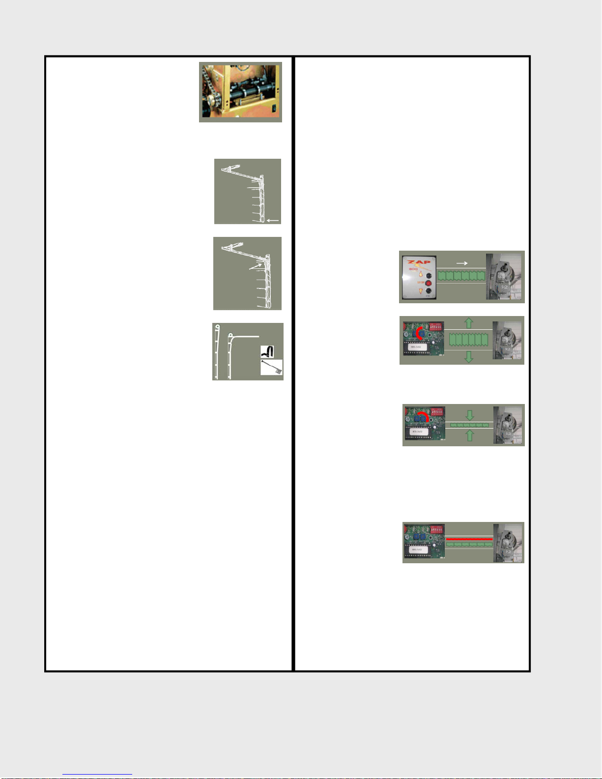
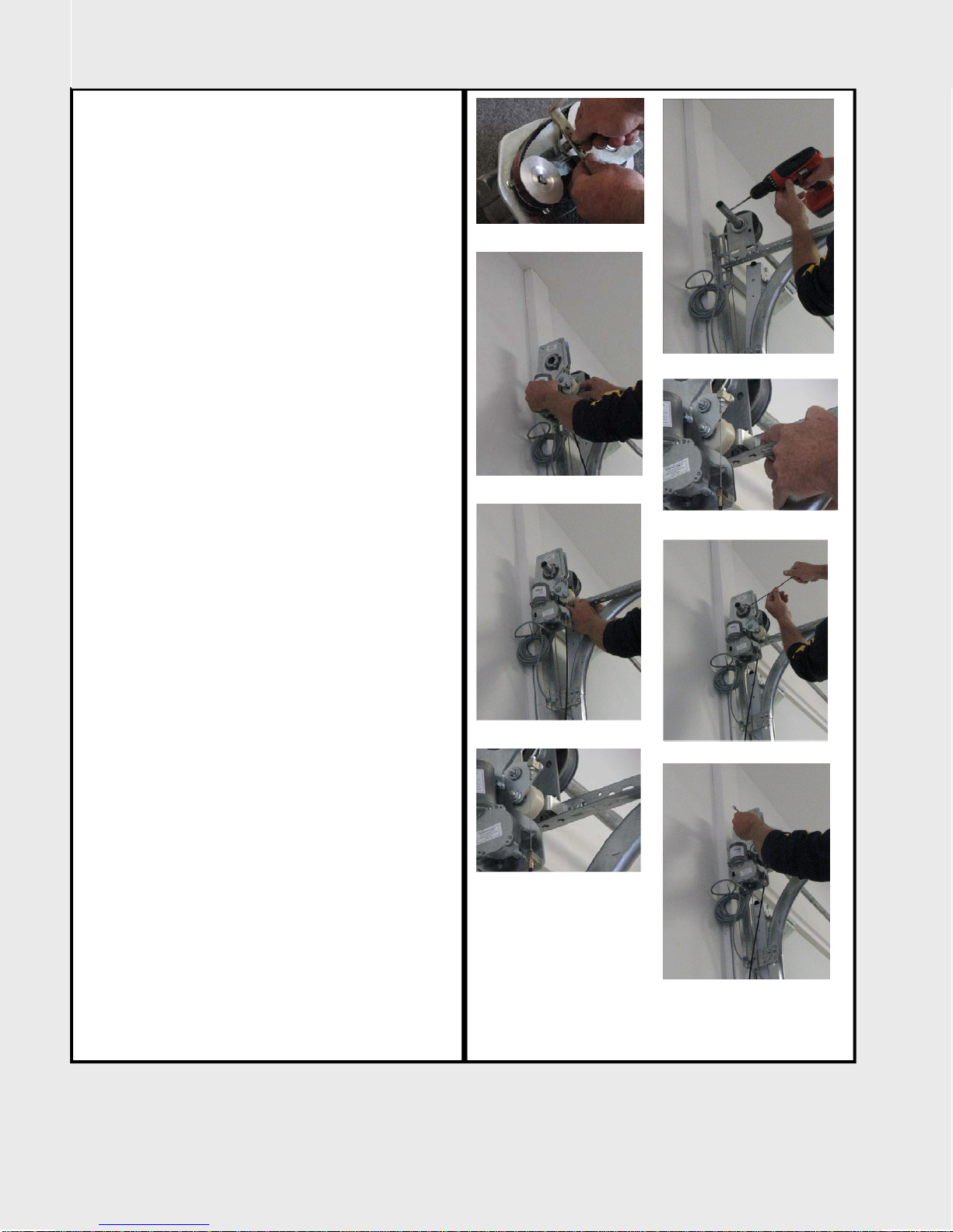
The limits of the door operator are
physical in nature.
The floor being the down limit.
(Figure A)
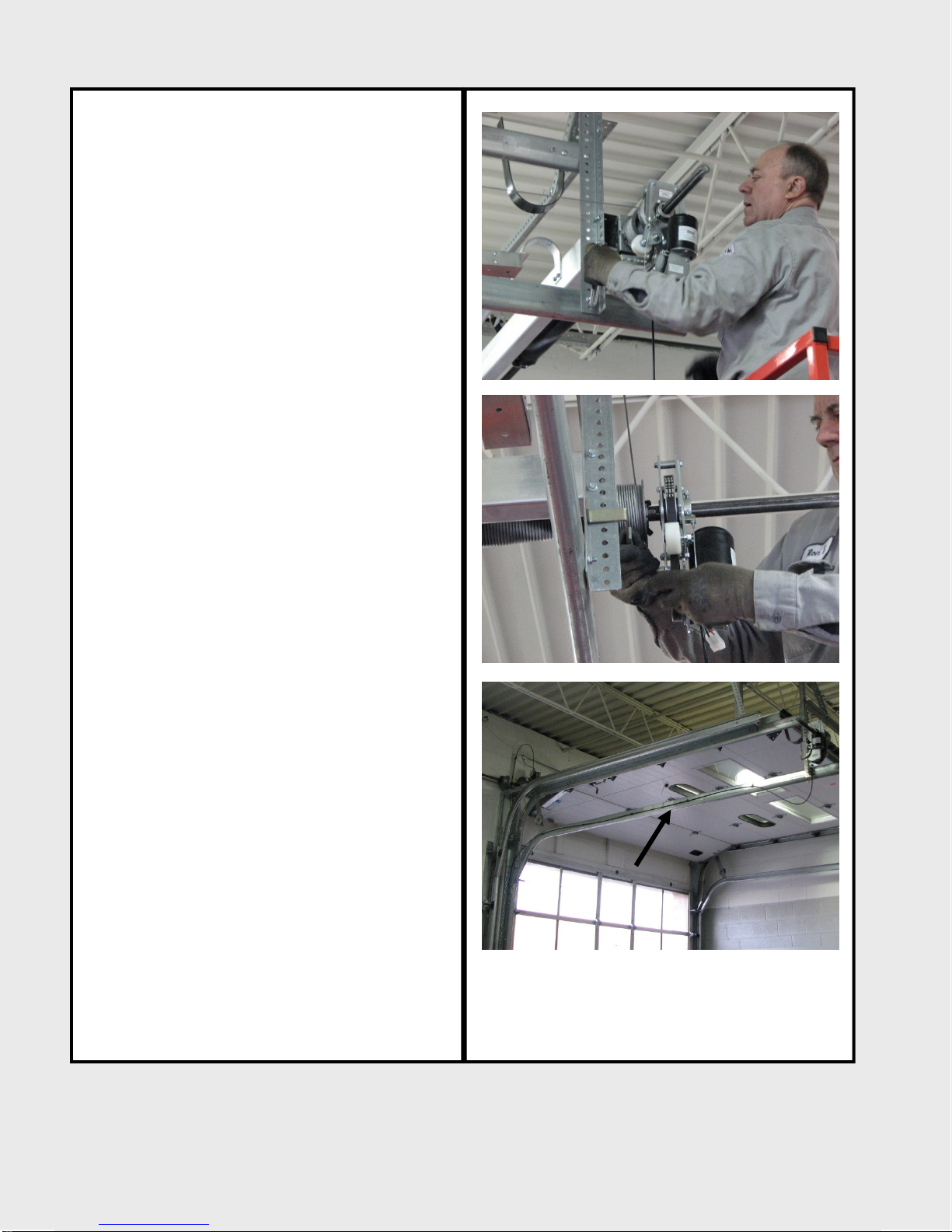
A physical stop for the upper limit.
On standard lift and low headroom
doors the physical stop is the track
radius as the door can only rise so
high into the radius before the
torsion shaft would have to counter
rotate to allow the door to go
higher. (Figure B)
On high-lift and vertical lift doors it
should be a bumper or pusher
spring. (Figure C)
The controller monitors the motor
load current. It therefore becomes a sensor that
automatically detects the door limits as well as
obstructions that can occur without the use of an
aftermarket safety edge. Because of its unique
abilities it can detect an obstructions on any part of
the door, not just the leading door edge.
Speed Change Point Calibration.
Calibration of slow speed change point is needed to
determine an approximation of the physical limits.
During the initial open calibration cycle, the
controller is measuring the run time to the upper
limit.
Approximately half way through the first open cycle
of operation, note that the operator will slow down.
This slow down is called a speed change point. After
completing the first up cycle, the run time to the
upper limit is stored into memory. The same thing
occurs on the close calibration cycle. Approximately
half way through the first close cycle of operation,
the operator will again slow down. After completing
the first close cycle, the close run time is stored into
memory as well and is compared to the open run
time.
During the second calibration run, the run times
are verified against the first set of run times. If
they match, they are stored into memory. It takes
2-3 complete cycles to fully calibrate the run time.
Once the operator has fully calibrated the run
times, the controller moves the opening speed
change point to within seconds of the end of the
calibrated open run time. Likewise, the controller
moves the closing speed change point to within
seconds of the end of it’s calibrated run time. This
is how the controller knows where the limits are
and where to stop.
Motor power and sensitivity potentiometer,
obstruction sensing, automatic reversing and
safety stop.
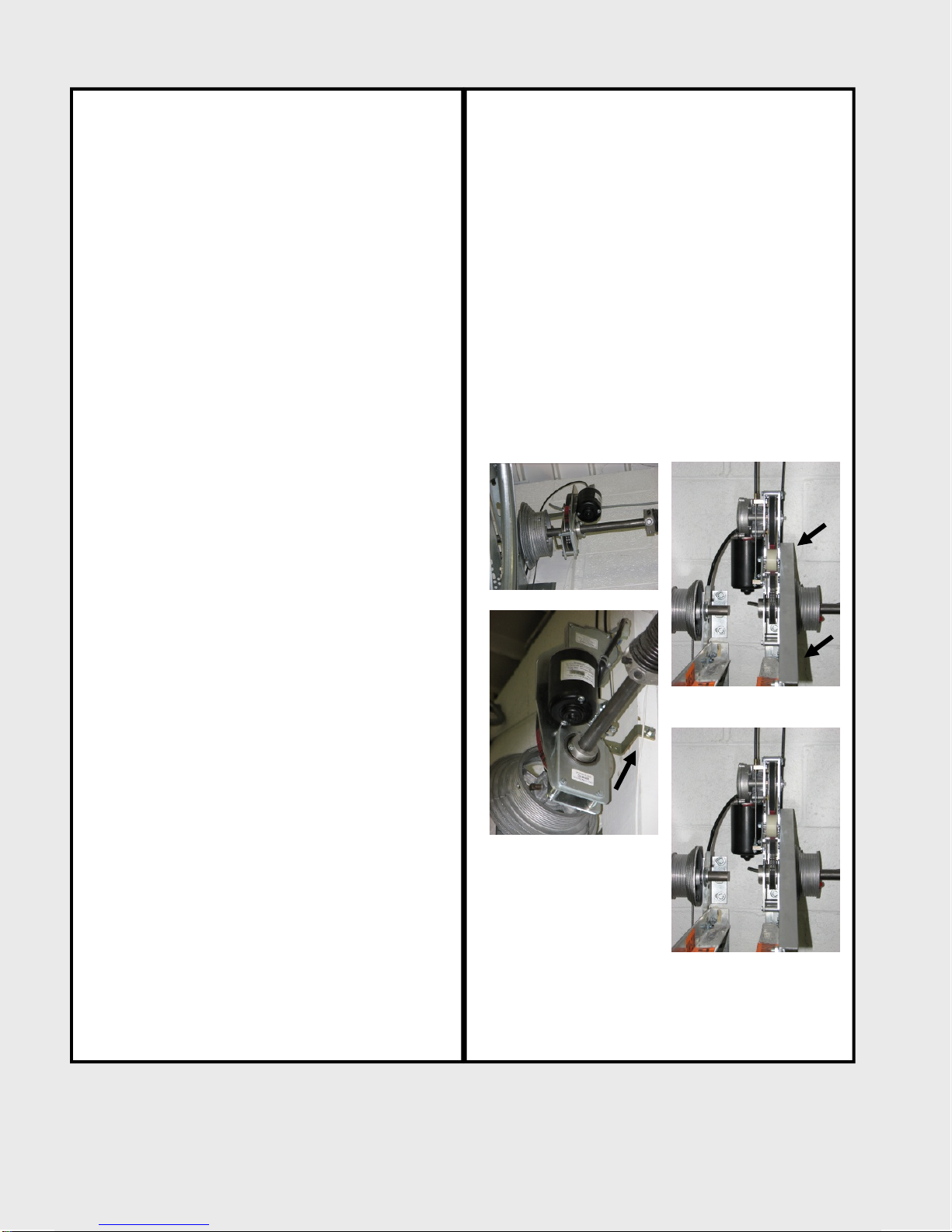
Picture if you will,
current flowing to the
motor.
(Figure D)
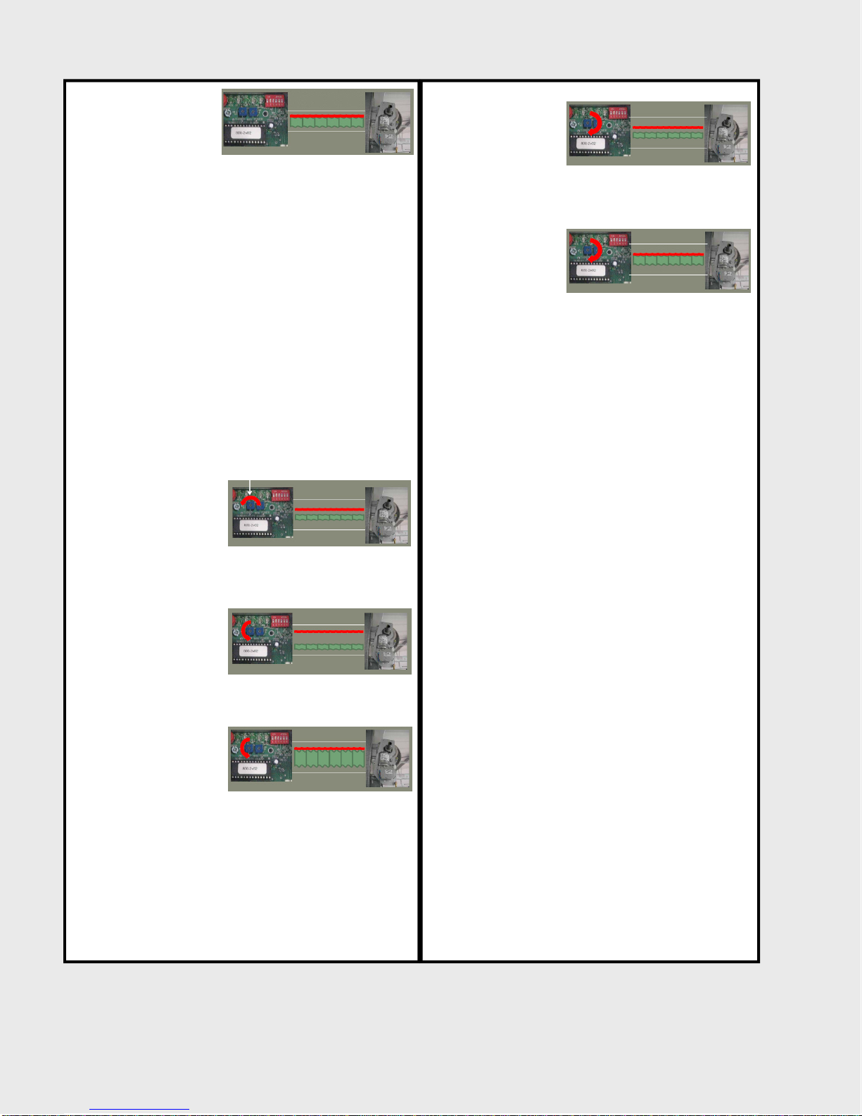
If you increase power
at the power
potentiometer you
open up the range of
power that can be
applied to the motor.
(Figure E)
If you decrease power
at the power
potentiometer it
closes the range of
power that can be
applied to the motor. (Figure F)
Inherent safety functions
Stop at limit, safety stop, and automatic reversing
The inherent safety
and sensitivity
function’s monitor the
system by mirroring
the motor current. If
the door meets an
obstruction in either direction, the current spikes.
(Figure F)
Continued on next page.
Figure C
Figure B
Figure F
Figure D
Figure E
Figure A
Figure F
4

Series 3 Technician’s Installation and Service Training Manual
Understanding How ZAP Commercial Operators Work
Series 3 Technician’s Installation and Service Training Manual
Understanding How ZAP Commercial Operators Work
Series 3 Understanding How ZAP Commercial Operators Work
ZAP Series 3
Simply Logical
ZAP Controls
100 Waterloo Blvd. Anglesey Business Park, Littleworth Road, Cannock, Staffordshire, England
UK Contact 011-44-154-387-9444 sales@zap-uk.com
USA Contact 931-510-4432 sales@zap-america.com
USA Tech Support 931-510-4432 via telephone or text
Online www.zap-uk.com
If the resistance on
the door is significant
enough to cause the
current demand to
spike to the setting of
the sensitivity
Potentiometer (Figure A), it causes a certain function
depending upon the direction of door travel and
where the door is in it’s cycle of operation.
If the door is near the end of the calibrated run time
in either the open or close direction, (after the speed
change point), the operator knows it is at the limit of
travel and to stop.
If the door is travelling in the open direction prior to
the open speed change point and the door meets an
obstruction on any part of the door, the operator
knows to activate the safety stop feature.
If the door is travelling in closed direction prior to the
close speed change point and meets an obstruction
on any part of the door, the operator knows to
activate the safety stop and reverse function and
return the door to the fully open position.
The sensitivity is
adjustable by
incrementally
increasing or
decreasing the
sensitivity potentiometer.
(Figure B)
If you decrease the
sensitivity on the
sensitivity
potentiometer, it
opens up the
tolerances of the
detection (Figure C).
Requiring a larger spike
in current to reach the
sensitivity setting,
making the operator
less sensitive to
detection of obstructions.
(Figure D)
If you increase the
sensitivity on the
sensitivity
potentiometer it
closes up the
tolerances of
the detection
(Figure E).
This makes the
operator more
sensitive to
detecting
obstructions.
Requiring much less
of spike in current to
reach the sensitivity setting.
(Figure F)
Figure C
Figure B
Figure F
Figure D
Figure E
5
Figure A

Series 3 Technician’s Installation and Service Training Manual
Commercial Operator Standard Mounting on a solid torsion shaft
Series 3 Commercial Operator Standard Mounting on a solid torsion shaft
ZAP Series 3
Simply Logical
ZAP Controls
100 Waterloo Blvd. Anglesey Business Park, Littleworth Road, Cannock, Staffordshire, England
UK Contact 011-44-154-387-9444 sales@zap-uk.com
USA Contact 931-510-4432 sales@zap-america.com
USA Tech Support 931-510-4432 via telephone or text
Online www.zap-uk.com
Materials Needed
Appropriate operator for door size. (See Brochure)
Tools required
3mm Allen Key, 10mm Wrench, drill, 1/4” Drill bit,
Appropriate mounting fasteners.
Fully read all instructions provided with the operator.
Remove and separate all contents from the box.
It is important to follow the steps in order to prevent
misalignment of the operator.
Locate the torque arm, torque arm bolt and spacer.
Attach the torque arm and spacer to the operator
into a position that you consider the approximate
distance to an open bolt hole on the track assembly.
(Figure A)
Slide the operator on the shaft and into position.
(Figure B) and check that the positioning of the
torque arm is correct. (Figure C)
If necessary, slide the operator off the shaft and
adjust the position of the torque arm. Reposition
operator back onto shaft. Note-the torque arm
should always be positioned in a horizontal manner,
never vertically. (Figure D)
Secure the torque arm to the track assembly through
an existing bolt hole using either the provided
fastener or one of suitable size to accommodate your
needs. Tighten the bolt securely into place.
(Figure E)
Tighten the bolt on the back of the operator holding
the torque arm to the operator.
Using the provided key stock (feather key). Insert it
fully into the keyway. (Figure F)
Tighten the set screw securely into place being
careful not to over tighten. (Figure G)
Tighten the lock nut on the set screw. Repeat
process for second set screw. (Figure H)
Locate the second set screw on the pulley and repeat
the processes for tightening the set screw and lock
nut. (Figure G & H)
To prevent accidental loss of key stock (feather key)
should the set screws accidentally back out, Use
electrical tape to wrap the key stock (feather key).
(Figure I)
Figure C
Figure B
Figure D
Figure E
Figure F
Figure G
Figure A
Figure H
Figure I
Series 3 Technician’s Installation and Service Training Manual
Commercial Operator Standard Mounting on a solid torsion shaft
6

Series 3 Technician’s Installation and Service Training Manual
Commercial Operator Standard Mounting a hollow torsion shaft
Series 3 Commercial Operator Standard Mounting on a hollow torsion shaft
ZAP Series 3
Simply Logical
ZAP Controls
100 Waterloo Blvd. Anglesey Business Park, Littleworth Road, Cannock, Staffordshire, England
UK Contact 011-44-154-387-9444 sales@zap-uk.com
USA Contact 931-510-4432 sales@zap-america.com
USA Tech Support 931-510-4432 via telephone or text
Online www.zap-uk.com
Materials Needed
Appropriate operator for door size. (See Brochure)
Tools required
3mm Allen Key, 10mm Wrench, drill, 1/4” Drill bit,
Appropriate mounting fasteners.
Remove and separate all contents from the box.
It is important to follow the steps in order to prevent
misalignment of the operator.
Locate the torque arm, torque arm bolt and spacer.
Attach the torque arm and spacer to the operator
into a position that you consider the approximate
distance to an open bolt hole on the track assembly
and secure finger tight. (Figure A)
Slide the operator on the shaft and into position.
(Figure B)
Check that the positioning of the Torque arm is
correct. (Figure C) If necessary, slide the operator off
the shaft and adjust the position of the torque arm.
Reposition operator back onto shaft. Note-the
torque arm should always be positioned in a
horizontal manner, never vertically. (Figure D)
Secure the torque arm to the track assembly through
an existing bolt hole using either the provided
fastener or one of suitable size to accommodate your
needs. Tighten the bolt securely into place.
(Figure F)
Using the 3mm Allen wrench, tighten one of the set
screws into position creating a mark on the torsion
shaft. (Figure G) Loosen the set screw and unbolt the
torque arm from its track position. Slide the operator
out of the way exposing the score mark.
Using the 1/4” drill bit and drill, drill a hole into one
side of the torsion being careful not to drill all the
way the way through the opposing wall of the shaft.
(Figure E)
Slide the operator back into position and re-secure
the torque arm to the track assembly. Tighten the
bolt securely into place. (Figure F) Tighten the bolt
on the back of the operator holding the torque arm
to the operator.
Replace the set screw that is to be used in the drilled
hole with the provided long set screw. Tighten the
set screw into the hole being mindful not to over
tighten. (Figure F) Tighten the lock nut on the set
screw. (Figure G) Repeat the tightening process for
second shorter set screw.
Figure C
Figure B
Figure D
Figure G
Figure E
Figure H
Figure A
Figure F
Series 3 Technician’s Installation and Service Training Manual
Commercial Operator Standard Mounting on a hollow torsion shaft
7

Series 3 Technician’s Installation and Service Training Manual
Commercial Operator Inverted Mounting
Series 3 Technician’s Installation and Service Training Manual
Commercial Operator Inverted Mounting
Series 3 Commercial Operator Inverted Mounting
ZAP Series 3
Simply Logical
ZAP Controls
100 Waterloo Blvd. Anglesey Business Park, Littleworth Road, Cannock, Staffordshire, England
UK Contact 011-44-154-387-9444 sales@zap-uk.com
USA Contact 931-510-4432 sales@zap-america.com
USA Tech Support 931-510-4432 via telephone or text
Online www.zap-uk.com
Materials Needed
Appropriate operator for door size. (See Brochure)
Tools required
3mm Allen Key, 10mm Wrench, drill, 1/4” Drill bit,
Appropriate mounting fasteners.
Assembly and Mounting
Follow the assembly instructions and basic mounting
techniques for standard installation on hollow and
solid torsion shafts.
Inverted mounts may happen outboard or inboard of
the cable drum. For mounts inboard of the cable
drum, ensure there is clearance between the
operator and the door at the point where the door
passes the operator.
Bowden Cable
It will be necessary to loop the Bowden cable over
either the jamb and track if mounted inboard of the
cable drums and over the motor if mounted outboard
of the cable drums. Using a cable clamp to hold the
Bowden cable in place for this application is
advisable, but it must not be so tight as the clamp,
bind or compress the sleeve of the Bowden cable
assembly. A heavy duty nylon wire tie will also
suffice when there is sufficient access to secure the
nylon wire tie.
Mounting inboard of the cable drum.
With the door in the closed position and the spring
tension completely relieved by completely unwinding
the torsion springs using the proper tools for
accomplishing the task, remove the bearing plate
and cable drum of the door.
Position the inverted operator in the direction for the
side of the door that best suits mounting of the
torque arm. (Figure A)
Never mount the torque arm into concrete or block
work using a concrete anchor. Only mount to steel or
to wood jambs that have been properly secured and
will not work loose with the applied torque of the
operator. (Figure B) If no mount to the wall or track
is available for securing the torque arm, it is ok to
develop your own mount using angle iron to mount
otherwise as exampled in Figure C.
Loop the Bowden Cable over the cable drum and
track assembly and mount the Bowden cable
mounting bracket located at the end of the Bowden
cable sheath securely as described in the Bowden
cable mounting instruction.
Mounting outboard of the cable drum.
Position the inverted operator in the direction for the
side of the door that best suits mounting of the
torque arm. (Figure A)
Never mount the torque arm into concrete or block
work using a concrete anchor. Only mount to steel or
to wood jambs that have been properly secured and
will not work loose with the applied torque of the
operator. (Figure B)
Loop the Bowden Cable over the operator and secure
as described above in the Bowden cable
section above.
Mount the Bowden cable mounting bracket located at
the end of the Bowden cable sheath securely as
described in the Bowden cable mounting instruction.
Continue with operator installation as per the normal
installation and set up instructions.
Figure A
Figure B
Figure C
Figure D
8

Series 3 Technician’s Installation and Service Training Manual
Commercial Operator Rear Mount Torsion Mounting
Series 3 Technician’s Installation and Service Training Manual
Commercial Operator Rear Mount Torsion Mounting
Series 3 Commercial Operator Rear Mount Torsion Mounting
ZAP Series 3
Simply Logical
ZAP Controls
100 Waterloo Blvd. Anglesey Business Park, Littleworth Road, Cannock, Staffordshire, England
UK Contact 011-44-154-387-9444 sales@zap-uk.com
USA Contact 931-510-4432 sales@zap-america.com
USA Tech Support 931-510-4432 via telephone or text
Online www.zap-uk.com
Materials Needed
Appropriate operator for door size. (See Brochure)
Tools required
3mm Allen Key, 10mm Wrench, drill, 1/4” Drill bit,
Appropriate mounting fasteners.
Appropriate Bowden Cable for height of door
(See Bowden Cable section Below)
Part# 900005 Additional Large offset torque arm.
Assembly and Mounting
Follow the assembly instructions and basic mounting
techniques for standard installation on hollow and
solid torsion shafts.
It may be necessary to reach around the cable drum
if it is mounted to the outside of the torsion shaft
bearing plate. To achieve this attach the additional
torque arm to the torque arm that is attached to the
operator as exampled in (Figure A)
Follow the standard assembly instructions and basic
mounting techniques for a standard installation on
hollow and solid torsion shafts.
It will be necessary to change the Bowden to a
longer Bowden Cable assembly to accomplish a rear
mount torsion application. The following sizes of
Bowden cables are available to accommodate
different height doors:
Part# 501255 12.30 Feet
Fits low headroom doors to 10’ High
Part# 501256 17.75 feet
Fits low headroom doors between 11’ to 16’ High
It will be necessary to attach the long Bowden cable
to the horizontal track towards the header of the
door. This can be typically achieved by drilling
spaced hole into the horizontal angle iron attached to
the horizontal track and utilizing a heavy duty nylon
cable tie to secure the Bowden along the horizontal
track. (Figure B)
Mount the Bowden cable mounting bracket located at
the end of the Bowden cable sheath securely as
described in the Bowden cable mounting instruction.
Figure B
Figure A
9

Series 3 Technician’s Installation and Service Training Manual
Commercial Operator Offset Mounting
Series 3 Technician’s Installation and Service Training Manual
Commercial Operator Offset Mounting
Series 3 Commercial Operator Offset Mounting
ZAP Series 3
Simply Logical
ZAP Controls
100 Waterloo Blvd. Anglesey Business Park, Littleworth Road, Cannock, Staffordshire, England
UK Contact 011-44-154-387-9444 sales@zap-uk.com
USA Contact 931-510-4432 sales@zap-america.com
USA Tech Support 931-510-4432 via telephone or text
Online www.zap-uk.com
Offset mounting may be achieved in extreme close
quarters mounting situations
An independently supported solid torsion shaft must
be utilized.
Normal installations would utilize two separate
toothed sprockets and appropriate roller chain to
bridge the drive components. (Figure A)
A 1:1 ratio is typically used on the chain sprockets
similar in diameter to the driven pulley on the
operator. (Pulley that mounts on the shaft.)
Once a suitable mounting shaft is in place, install the
operator as described on the standard mounting
page for solid torsion shafts.
Figure A
10

Series 3 Technician’s Installation and Service Training Manual
Commercial Operator Front Mount Low Head Room Mounting
Series 3 Commercial Operator Front Mount Low Head Room Torsion Mounting
ZAP Series 3
Simply Logical
ZAP Controls
100 Waterloo Blvd. Anglesey Business Park, Littleworth Road, Cannock, Staffordshire, England
UK Contact 011-44-154-387-9444 sales@zap-uk.com
USA Contact 931-510-4432 sales@zap-america.com
USA Tech Support 931-510-4432 via telephone or text
Online www.zap-uk.com
Mounting:
Front mount low head room mounting is feasible with
the ZAP operator.
Depending upon the cable drum width and or
diameter, it may require either a larger or additional
torque arm to facilitate reaching around the cable
drum to mount to the track assembly, developing a
separate mounting point for the torque arm
altogether.
If it is required to develop a separate mounting point
it is important to note that the mounting should not
be into a masonry wall. The push and pull torque of
the operation of the operator will cause the mounting
bracket to pull free from masonry over time.
Clearance:
If additional clearance is required in the opening it is
feasible to reverse the cable drums and torsion
springs to allow the cables to come off of the interior
side of the cable drum. This will allow for additional
door clearance in the opening. Consult you door
manufacturer for proper methods on reversing your
torsion springs and cable drums to gain this
additional clearance.
Series 3 Technician’s Installation and Service Training Manual
Commercial Operator Front Mount Low Head Room Torsion Mounting
11

Series 3 Technician’s Installation and Service Training Manual
Commercial Dead Axle Sheet Door Operator Mounting
Series 3 Technician’s Installation and Service Training Manual
Commercial Dead Axle Sheet Door Operator Mounting
Series 3 Commercial Dead Axle Sheet Door Operator Mounting
ZAP Series 3
Simply Logical
ZAP Controls
100 Waterloo Blvd. Anglesey Business Park, Littleworth Road, Cannock, Staffordshire, England
UK Contact 011-44-154-387-9444 sales@zap-uk.com
USA Contact 931-510-4432 sales@zap-america.com
USA Tech Support 931-510-4432 via telephone or text
Online www.zap-uk.com
Materials Needed
Appropriate operator for door size. (See Brochure)
Tools required
4mm Allen Key, 10mm Wrench, drill, 1/4” Drill bit,
Appropriate mounting fasteners.
Remove and separate all contents from the box.
Verify the shaft diameter is the is 1-1/4”-1-5/16” in
diameter. (Figure A) If it is 1” in diameter use
adapter insert PN ZA0191.
Determine hole diameter in end of barrel and select
appropriate tongue for the application.
Bolt the appropriate tongue for door to the Pulley
(Finger tight) (Figure B)
For Installation on a new install door: Install
operator before installing door by sliding operator
over the shaft.
Align and insert the tongue into hole located on the
end of the drum.
Mark the position and slide the operator out far
enough to tighten the fasteners securely. (Figure B)
Slide the operator back into position.
Position operator so that it will be vertical when door
is installed. (Figure C) Note: the flat spot on the
bottom of the pulley boss is designed to rest on the
door support bracket.
Tighten set screws being careful not to over torque.
(Figure D)
Install the door in accordance with the manufacturers
instructions.
For electrical operation, it is important that the door
roll (curtain) is level.
For Retrofit Installation: With the door fully raised
and secured to prevent its unrolling, remove spring
tension per the door manufacturers instructions.
On the end of the door you wish to install the
opener, unbolt the curtain shaft from its support
bracket.
Using a mechanical lift raise that end of the door to a
height sufficient to allow half the diameter of the
operator driven pulley to pass over door support
bracket.
Hold the operator 90 degrees to the wall and slide
the operator over the shaft and into position.
Once on the shaft and passed over the door support
bracket, rotate the operator to a vertical position.
Align and insert the tongue into hole located on the
end of the drum.
Mark the position and slide the operator out far
enough to tighten the fasteners securely.
Slide the operator back into position.
Position operator so that it will be vertical when door
is installed. (Figure B) Note: the flat spot on the
bottom of the pulley boss is designed to rest on the
door support bracket.
Tighten set screws being careful not to over torque.
(Figure C)
Lower the door back into position, secure and
re-tension the counterbalance spring per the
manufacturer’s instructions.
Continue with installation and tensioning of the
Bowden cable. (See Bowden cable installation and
tensioning sections)
Figure A
Figure B
Figure C
Figure D
12

Series 3 Technician’s Installation and Service Training Manual
Commercial Live Axle Sheet Door Operator Mounting
Series 3 Technician’s Installation and Service Training Manual
Commercial Live Axle Sheet Door Operator Mounting
Series 3 Commercial Live Axle Sheet Door Operator Mounting
ZAP Series 3
Simply Logical
ZAP Controls
100 Waterloo Blvd. Anglesey Business Park, Littleworth Road, Cannock, Staffordshire, England
UK Contact 011-44-154-387-9444 sales@zap-uk.com
USA Contact 931-510-4432 sales@zap-america.com
USA Tech Support 931-510-4432 via telephone or text
Online www.zap-uk.com
ZAP 825 SS Live axle sheet door operators are the
same as the standard 825 commercial sectional door
operator with the exception of a shorter Bowden
cable.
Live Axle rolling sheet doors are typically 1” hollow
axles. However, some manufacturers do use 1-5/6”
axles. Typically these axles do not extend far enough
to allow the installation of a ZAP operator without the
addition of a shaft adapter.
ZAP Controls does not manufacture an adapter to
accommodate the installation. For 1” door shafts, an
adapter can be made from an 8” piece of solid
torsion shaft. It will require that approximately 4” of
the shaft be turned down for insertion into the hollow
1” shaft of the door shaft. After insertion it will be
required to drill and through bolt the inserted shaft
to the door shaft.
On doors with 1-5/16” shafts it is feasible to use an
8” piece of hollow or solid shaft. The inside diameter
of the 1-5/16”axle is adequate to accept the insertion
of the adapter into the door axle shaft. After inser-
tion it will be required to drill and through bolt the
inserted shaft to the door shaft.
Once the adapter shaft is installed proceed with the
installation as described in the standard commercial
operator instruction on wither hollow or solid shafts
as your particular situation dictates.
13

Series 3 Technician’s Installation and Service Training Manual
Commercial Compact Dead Axle Sheet Door Operator Mounting
Series 3 Technician’s Installation and Service Training Manual
Commercial Compact Dead Axle Sheet Door Operator Mounting
Series 3 Commercial Compact Dead Axle Sheet Door Operator Mounting
ZAP Series 3
Simply Logical
ZAP Controls
100 Waterloo Blvd. Anglesey Business Park, Littleworth Road, Cannock, Staffordshire, England
UK Contact 011-44-154-387-9444 sales@zap-uk.com
USA Contact 931-510-4432 sales@zap-america.com
USA Tech Support 931-510-4432 via telephone or text
Online www.zap-uk.com
Installation
The 827 operator is designed to take the place of the
door spacer that exists between the door and the
axle mounting bearing plate. Currently the operator
is verified as suitable for installation on the US Door
Model 502 and Janus 1” dead axle mini warehouse
rolling door.
During initial door installation, instead of installing
the spacer on the right side axle, slide the 8271
Compact Operator onto the non winding side axle
and engage the drive tongue on the large pulley into
one of the holes in the door roll drum plate. If no
hole suitable lines up or exists it will be necessary to
mark and drill a 1/2” hole into the door roll drum
plate.
(Figure A)
Slip the brackets onto the axle ends rotating the
8271 Compact Operator until the operator plate ears
sit either side of the axle bracket. (Figure B)
Now continue with the door manufacturers
installation instructions.
(Figure A)
(Figure B)
14

Series 3 Technician’s Installation and Service Training Manual
Bowden Cable and Over-Ride Lever Mounting
Series 3 Technician’s Installation and Service Training Manual
Bowden Cable and Over-Ride Lever Mounting
Series 3 Bowden Cable and Over-Ride Lever Mounting
ZAP Series 3
Simply Logical
ZAP Controls
100 Waterloo Blvd. Anglesey Business Park, Littleworth Road, Cannock, Staffordshire, England
UK Contact 011-44-154-387-9444 sales@zap-uk.com
USA Contact 931-510-4432 sales@zap-america.com
USA Tech Support 931-510-4432 via telephone or text
Online www.zap-uk.com
Tools required
Drill, 1/4” Drill bit, Appropriate mounting fasteners,
Appropriate wrenches and screwdrivers.
Installation:
After the operator has been mounted properly, locate
the mounting bracket on the end of the Bowden
cable black sheath. (Figure A)
The Bowden cable may be mounted to either the
Jamb or the track assembly. If mounting the
Bowden cable bracket to the track assembly, you
must mount the over-ride lever to the track
assembly as well. If mounting the Bowden cable
bracket to the door jamb, then the over-ride lever
must be mounted to the door jamb as well. Never
combine the two methods of mounting.
After locating the Bowden cable mounting bracket,
bring it to the desired surface you wish to mount it
to, either the track assembly or the door jamb.
(Figure B)
Next, lift the bracket at least 6 inches to allow
flexibility in the Bowden cable and mark for drilling or
mounting. The flexibility created in the Bowden cable
is necessary to ensure proper tensioning of the
operator belt. This also allows enough flexibility in
the Bowden cable to permit the removal of the
operator in the event of the need to replace the
operator belt after wearing out, without having to
disassemble the Bowden cable assembly. (Figure B)
If track mounting, use the drill and 1/4” bit to drill
the to marked holes in the track assembly. Using the
provided flat head fasteners for mounting the
Bowden Cable secure the Bowden cable bracket into
place.
If mounting to the door jamb, use a fastener of
appropriate size and design for the material to which
you are mounting. (Figure C)
It is not advisable to mount the over-ride lever
directly to the D shackle. Add an minimum of five
lengths of the provided chain to the D shackle to
facilitate future adjustment. If extra length is re-
quired to reach the desired mounting height of the
over-ride lever, attach the provided extension chain
to the “D” Shackle on the end of the Bowden Cable
and cut the chain at the desired height. (Figure D)
Locate the over-ride lever and adjust the hook out to
the fully extended position. (Figure E)
Insert the hook of the over-ride lever into the end
link of the extension chain. Pull down on the lever to
take up the belt slack on the operator. Position the
over-ride lever in the desired location (Figure F) and
mark for drilling or mounting. (Figure G)
Remove the over-ride lever from the chain or “D”
shackle and mount the over-ride lever in the marked
position. (Figure H)
Re-insert the hook into the extension chain and
proceed to the Setting proper belt tension with the
over-ride lever instruction page.
On the Chain hoist model operator (8826), note that
the first push down of the over-ride lever is simply
lifting the chain hoist off of the spur gear.
A secondary push down on the lever is required to
tension the belt.
Figure A
Figure B
Figure C
Figure D
Figure E
Figure F
Figure G
Figure I
15

Series 3 Technician’s Installation and Service Training Manual
Setting Belt Tension with the Over-Ride Lever
Series 3 Technician’s Installation and Service Training Manual
Setting Belt tension with the Over-Ride Lever
Series 3 Setting Belt Tension Override Lever Instruction
ZAP Series 3
Simply Logical
ZAP Controls
100 Waterloo Blvd. Anglesey Business Park, Littleworth Road, Cannock, Staffordshire, England
UK Contact 011-44-154-387-9444 sales@zap-uk.com
USA Contact 931-510-4432 sales@zap-america.com
USA Tech Support 931-510-4432 via telephone or text
Online www.zap-uk.com
Tools required
Appropriate wrench
Connect the over-ride lever hook to the chain
attached to the D shackle on the end of the Bowden
cable. (Figure A)
Press down on the over-ride lever until the belt feels
fully tensioned without locking the lever down.
(Figure B)
Looking at the handle of the lever as if it were the
hand of a clock, it should be located just above the
3:00 o’clock or 9:00 o’clock position, depending upon
how you are observing it. (Figure B)
If it is lower than the 9:00 or 3:00 o’clock position,
adjust the hook tighter until the correct position is
achieved when pressing down of the lever. (Figure C)
Once proper tension is achieved, lock the handle into
place. (Figure D)
After completing operator the initial operator
calibration cycles, recheck belt tension using the
above methods. During initial tensioning the belt will
have tensioned more on the side of the tensioning
wheel than on the opposing side of the pulley. This
will have evened out during the calibration cycle and
will require a small amount of adjustment.
Figure B
Figure A
Figure C
Figure D
16

Series 3 Technician’s Installation and Service Training Manual
Controller Case Mounting Instruction
Series 3 Technician’s Installation and Service Training Manual
Controller Case Mounting Instruction
Series 3 Controller Mounting Instruction
ZAP Series 3
Simply Logical
ZAP Controls
100 Waterloo Blvd. Anglesey Business Park, Littleworth Road, Cannock, Staffordshire, England
UK Contact 011-44-154-387-9444 sales@zap-uk.com
USA Contact 931-510-4432 sales@zap-america.com
USA Tech Support 931-510-4432 via telephone or text
Online www.zap-uk.com
Warning Electrical
Shock Hazard
To prevent serious injury or death
always ensure power is disconnected
when wiring anything into the ZAP
Controller.
Tools required
Slotted screwdriver, Drill, 6” long Phillips driver bit,
Phillips screwdriver, Appropriate mounting fasteners.
Using a standard screwdriver, insert it into the cover
retaining screws located in each corner of the
controller (Figure A), and loosen the retaining screws
to open the case lid. (Figure B)
Using a general purpose screw with a head diameter
small enough to fit into the corner pillars of the con-
troller, mount the controller a minimum of 5’ above
the ground. Do not mount through the back of the
controller case by removing the circuit board as this
may allow moisture to enter the controller or short
circuit the control board if it touches the fastener
used. Mounting through the back of the controller
case will void the manufacturers’ warranty if damage
occurs. (Figure C & D)
Only mount the controller with the conduit access
knock-out or pre-drilled access holes pointed down.
Only use the knock-out hole to introduce conduit or
wiring into the controller. Moisture can and will
condense in conduit due to the warmth generated by
the controller. If the controller is mounted upside
down and conduit is not used, any liquid spilled on
top of the controller can enter into the controller and
drip the board causing a short circuit. Introducing
conduit in any fashion other than from the bottom of
the controller will void the manufacturers’ warranty if
damage occurs.
You are not limited to mounting the controller at the
five foot height. The controller may be mounted high
by the operator or remotely, as long as the distance
away from the operator does not exceed the length
of the provided motor cable. (Figure E)
A remote wall station control may then be run in a
series from the controller. See remote wall station
wiring page.
Figure A
Figure B
Figure C
Figure D
Figure E
17

Series 3 Technician’s Installation and Service Training Manual
115V 1 Phase Wiring Instruction
Series 3 Technician’s Installation and Service Training Manual
115V 1 Phase Wiring Instruction
Series 3 115V 1 Phase Wiring Instruction
ZAP Series 3
Simply Logical
ZAP Controls
100 Waterloo Blvd. Anglesey Business Park, Littleworth Road, Cannock, Staffordshire, England
UK Contact 011-44-154-387-9444 sales@zap-uk.com
USA Contact 931-510-4432 sales@zap-america.com
USA Tech Support 931-510-4432 via telephone or text
Online www.zap-uk.com
Warning Electrical
Shock Hazard
To prevent serious injury or death
always ensure power is disconnected
when wiring anything into the ZAP
Controller.
Tools Required
Small technicians slotted screwdriver
ZAP Controller Power Wiring Instruction
ZAP Controllers are designed to accept 115VAC and
230VAC in North America. Note the voltage selector
switch located on the main board in (Figure A),
highlighted in yellow.
Please ensure this is set to the correct voltage prior
to turning on power supply. Introducing 230VAC
while set on 115VAC will damage the board and
require the board to be replaced. No warranty is
available for failure to follow the wiring instruction.
All wiring plugs are removable for easy wiring access
with the exception of the grounding terminal.
Power wiring access on the control board is located
at he green plug on the control board. (Figure B).
The terminals are labeled on the board from Left to
right as follows: Live In, Neutral, Neutral, Light
Control. Use the two left hand terminals for power
introduction.
The Gray grounding terminal strip is located to the
left of the green power plug. (Figure C).
Molded knock outs or pre-drilled ingress holes are
provided on the bottom of the controller for the
introduction of conduit and wiring. Only use these
knock outs for the introduction of wiring into the
controller. Do not mount the controller case upside
down to introduce conduit or wiring into the
controller. This will void the manufacturers warranty
Wiring Diagram: (Figure D)
115VAC 1 Phase
Figure A
Figure C
Figure D
Ground
155V Live
Neutral
Figure B
18

Series 3 Technician’s Installation and Service Training Manual
208-230V 1 Phase Wiring Instruction
Series 3 Technician’s Installation and Service Training Manual
208-230V 1 Phase Wiring Instruction
Series 3 208-230V 1 Phase Wiring Instruction
ZAP Series 3
Simply Logical
ZAP Controls
100 Waterloo Blvd. Anglesey Business Park, Littleworth Road, Cannock, Staffordshire, England
UK Contact 011-44-154-387-9444 sales@zap-uk.com
USA Contact 931-510-4432 sales@zap-america.com
USA Tech Support 931-510-4432 via telephone or text
Online www.zap-uk.com
Warning Electrical
Shock Hazard
To prevent serious injury or death
always ensure power is disconnected
when wiring anything into the ZAP
Controller.
Tools required
Small technicians slotted screwdriver
ZAP Controller Power Wiring Instruction
ZAP Controllers are designed to accept 115VAC and
230VAC in North America. Note the voltage selector
switch located on the main board in (Figure A),
highlighted in yellow.
Please ensure this is set to the correct voltage prior
to turning on power supply. Introducing 230VAC
while set on 115VAC will damage the board and
require the board to be replaced. No warranty is
available for failure to follow the wiring instruction.
All wiring plugs are removable for easy wiring access
with the exception of the grounding terminal.
Power wiring access on the control board is located
at he green plug on the control board. (Figure B).
The terminals are labeled on the board from Left to
right as follows: Live In, Neutral, Neutral, Light
Control. Use the two left hand terminals for power
introduction.
The Gray grounding terminal strip is located to the
left of the green power plug. (Figure C).
Molded knock outs or pre-drilled ingress holes are
provided on the bottom of the controller for the
introduction of conduit and wiring. Only use these
knock outs for the introduction of wiring into the
controller. Do not mount the controller case upside
down to introduce conduit or wiring into the
controller. This will void the manufacturers warranty
Wiring Diagram: (Figure C)
230VAC 1 Phase
Figure C
Ground
Neutral
Figure A
Figure C
Figure B
230VAC 1ph
19

Series 3 Technician’s Installation and Service Training Manual
480 3 Phase Wiring Instruction
Series 3 Technician’s Installation and Service Training Manual
480 3 Phase Wiring Instruction
Series 3 480V 3 Phase Wiring Instruction
ZAP Series 3
Simply Logical
ZAP Controls
100 Waterloo Blvd. Anglesey Business Park, Littleworth Road, Cannock, Staffordshire, England
UK Contact 011-44-154-387-9444 sales@zap-uk.com
USA Contact 931-510-4432 sales@zap-america.com
USA Tech Support 931-510-4432 via telephone or text
Online www.zap-uk.com
Warning Electrical
Shock Hazard
To prevent serious injury or death
always ensure power is disconnected
when wiring anything into the ZAP
Controller.
Tools Required
Small technicians slotted screwdriver
ZAP Controller Power Wiring Instruction
480 3 phase is only available as a special order on
ZAP 8800 controllers.
There is no voltage selector switch on 48O 3 phase
8800 Controllers.
All wiring plugs are removable for easy wiring access
with the exception of the grounding terminal.
Power wiring access on the control board is located
on a piggy back board in the area heighted in red
(Figure A).
Molded knock outs or pre-drilled ingress holes are
provided on the bottom of the controller for the
introduction of conduit and wiring. Only use these
knock outs for the introduction of wiring into the
controller. Do not mount the controller case upside
down to introduce conduit or wiring into the
controller. This will void the manufacturers warranty.
Wiring requirement:
14AWG Maximum size wiring.
Wire Leg 1 of 480 3 ph to live connection 1 on 480 3
phase auxiliary connection board.
Wire Leg 2 of 480 3ph to live connection 2 on
auxiliary connection board,
Wire Ground to Ground on main circuit board
Wiring Diagram: (Figure A)
480V 3 Phase
Figure A
20
Table of contents
Other Zap Garage Door Opener manuals
Popular Garage Door Opener manuals by other brands

Topens
Topens MultiRuta CASAR 800 user manual

Centurion
Centurion D2 Turbo installation manual

Nice
Nice THOR Instructions and warnings for the fitter

Chamberlain
Chamberlain Security+ 6200 owner's manual

CENTURION SYSTEMS
CENTURION SYSTEMS SDO4 SMART quick start guide

LOBAS
LOBAS Major LO TF Assembly instruction