zarges PAX Tower 5535212 User manual

12/2021
P/N 122328-01
en Aluminium Towers
3T – Through The Trapdoor

PAXTower 3T Instruction Manual2
Contents
1 Safety First......................................................................3
1.1 Introduction.................................................................. 3
1.2 Compliances................................................................. 3
1.3 Preparation and inspection ......................................... 3
2 Safe use ..........................................................................4
2.1 Lifting of equipment..................................................... 4
2.2 Stabilisers..................................................................... 4
2.3 Movement..................................................................... 4
2.4 During use.................................................................... 5
2.5 Maintenance - storage - transport ............................. 6
3 Assembly overview .........................................................7
4 Technical Data.................................................................9
5 Quantity Schedule .........................................................10
6 Assembly Procedure.....................................................12
6.1 Assembling the base unit, 0.6m PH.......................... 12
6.2 Assembling the 3T mobile towers
1.6m, 3.6m and 5.6m PH............................................ 14
7 Notes on dismantling ....................................................19
8 Additional fitting ...........................................................20
8.1 Fitting adjustable legs to swivel castors................... 20
8.2 Fitting stabiliser extensions ...................................... 21
9 Dimensions ...................................................................23
10 Identification .................................................................24
11 Structural safety ...........................................................25

3
1 Safety First
1.1 Introduction
Read this instruction manual carefully.
Note that diagrams are for illustrative purposes only.
Instruction manuals are also available to download from our
website at zarges.com/uk.
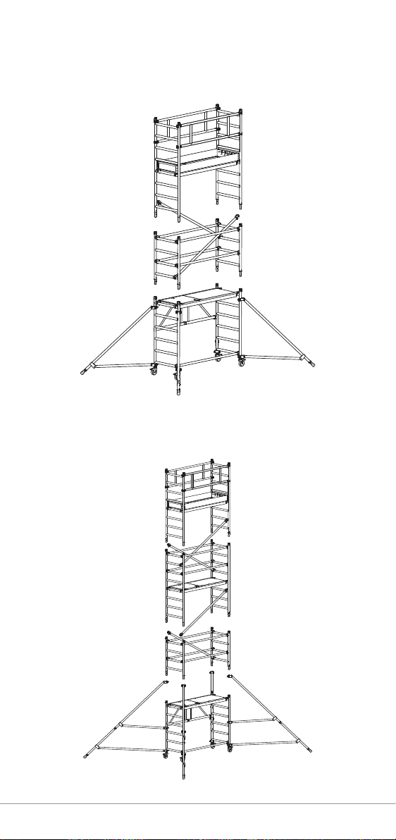
PAXTower mobile aluminium towers are light-weight scaffold
towers used throughout the building and construction industry
for both indoor and outdoor access solutions where a stable
and secure platform is required. Ideal for maintenance and
installation work or short-term access, the highly versatile
towers provide a strong working platform for a variety of
heights.
This instruction manual provides you with step by step
instructions to ensure your system is erected easily and safely,
using the 3T (Through The Trapdoor) method. The law requires
that personnel erecting, dismantling or altering towers must
be competent. Any person erecting a mobile tower must have
a copy of this instruction manual. For further information
on the use of mobile access and working towers consult the
PASMA operators code of practice.
If you need further information, design advice, additional
instruction manuals or any other help with this product,
please contact the manufacturer on +44 (0)1908 641118 or
email sales@zarges.co.uk.
1.2 Compliances
The PAXTower 3T aluminium towers have been
tested and certified to EN 1004.
1.3 Preparation and inspection
Inspect the equipment before use to ensure that it is not
damaged and that it functions properly. Damaged or incorrect
components should not be used.

PAXTower 3T Instruction Manual4
2 Safe use
• Check that all components are onsite, undamaged and that
they are functioning correctly - (refer to Quantity Schedule,
page 10). Damaged or incorrect components should not be
used.
• Check if the ground on which the mobile access tower is to
be erected and moved is capable of supporting the tower.
• The safe working load is 208 kg for the one working platform
level, uniformly distributed.
• Any platform used as a working platform must be fitted with
toe boards.
• Towers must always be climbed from the inside during
assembly and use.
• Adjustable legs should only be used for levelling.
• This tower may be assembled by a single person, but it is
recommended that for 5.6 m PH a second person is used to
pass up components.
2.1 Lifting of equipment
• Tower components should be lifted using a reliable lifting
material (e.g. strong rope) employing a reliable knot (e.g.
clove hitch) to ensure safe fastening and always lift within
the footprint of the tower.
• Assembled mobile towers should not be lifted with a crane
or other lifting devices.
2.2 Stabilisers
• Stabilisers or outriggers should always be fitted when
specified. The Quantity Schedules show the recommended
stabilisation. In circumstances where there is restricted
ground clearance for stabilisers, contact the manufacturer.
2.3 Movement
The tower should only be moved by manual effort, and only
from the base.
• Beware of live electrical apparatus when moving the tower
(particularly overhead), plus wires or moving parts of
machinery.

5
• No person or materials should be on the tower during
movement.
• Caution should be exercised when wheeling a tower over
rough, uneven or sloping ground, taking care to unlock
and lock castors. If stabilisers are fitted, they should only
be lifted a maximum of 25mm above the ground to clear
ground obstructions.
• Before use, check that the tower is still correct and
complete.
• After every movement of the tower, use a spirit level to
check that it is vertical and level and set the adjustable legs
as required.
2.4 During use
• Effect of wind conditions on site must be considered before
assembly and during use.
• This structure has been assessed for windloads equating to
27mph (43kph,12m/s).
• If greater windspeeds are forecast the tower must be
dismantled while still safe to do so.
Wind
description
Beaufort
scale
Beaufort
No.
Speed in
mph
Speed in
m/sec
Medium Breeze
Raises dust and
loose paper, twigs
snap off
4 8-12 4-6
Strong Breeze
Large branches in
motion, telegraph
wires whistle
6 25-31 11-14
Gale Force Walking is difficult 8 39-46 17-21
• Beware of open ended buildings, which can cause a
funnelling effect.
• Do not abuse equipment. Damaged or incorrect components
should not be used.
• Raising and lowering components, tools, and/or materials
by rope should be conducted within the lower base. Ensure
that the safe working load of the supporting decks and the
tower structure is not exceeded.
• The assembled tower is a working platform and should not
be used as a means of access or egress to other structures.
• Beware of horizontal forces (e.g. power tools) which could
generate instability. Maximum horizontal force: 30 kg.
• Do not use boxes or stepladders or other objects on the
platform to gain extra height.

PAXTower 3T Instruction Manual6
• After assembly the tower should be regularly inspected by a
competent person to ensure that no environmental changes
have occurred that may affect safe use.
2.5 Maintenance - storage - transport
• All components and their parts should be regularly
inspected to identify damage; particularly to joints. Lost
or broken parts should be replaced, and any tubing with
indentation greater than 5 mm should not be used and put
to one side for manufacture repair. Adjustable leg threads
should be cleaned and lightly lubricated to keep them free
running.
• Brace claws, frame interlock clips, trapdoor latches and
platform windlocks should be regularly checked to ensure
they lock correctly.
• Components should be stored with due care to prevent
damage.
• Ensure components are not damaged by excessive strapping
forces when transported.
• Danger of falling due to slippery tread surfaces!
Lubricating oil on tread surfaces causes falls and injuries.
Remove superfluous oil.

7
3 Assembly overview
PAX Tower Base Unit , 0.6m PH
(Art.-No.. 5535212)
PAX 3T, 1.6 m PH
(Art.-No.. 5535122)

PAXTower 3T Instruction Manual8
PAX 3T, 3.6 m PH
(Art.-No.. 5535142)
PAX 3T, 5.6 m PH
(Art.-No.. 5535162)

9
4 Technical Data
PAXTower Base Unit, 0.6m PH
Art.-No. 5535102
Weight 28.31kg
Working height 2.6m
Scaffold height 1.6m
Platform height 0.6m
PAXTower EN1004 Base Tower, 0.6m PH
Art.-No. 5535212
Weight 58.07kg
Working height 2.6m
Scaffold height 1.6m
Platform height 0.6m
PAXTower 3T, 1.6m PH
Art.-No. 5535122
Weight 70.4kg
Working height 3.6m
Scaffold height 2.6m
Platform height 1.6m
PAXTower 3T, 3.6m PH
Art.-No. 5535142
Weight 104.24kg
Working height 5.6m
Scaffold height 4.6m
Platform height 3.6m
PAXTower 3T, 5.6m PH
Art.-No. 5535162
Weight 115.92kg
Working height 7.6m
Scaffold height 6.6m
Platform height 5.6m

PAXTower 3T Instruction Manual10
5 Quantity Schedule
List of scaffold units with packages
Product
code Product description
5535212 5535122 5535142 5535162
0.6m PH 1.6m PH 3.6m PH 5.6m PH
2.6m WH 3.6m WH 5.6m WH 7.6m WH
5535102 Base Pack 1 1 1 1
5535502 EN1004 Pack 1 1 1 1
5535532 1m Extension Pack 3T - 1 1 1
5535542 2m Extension Pack 3T - - 1 2
5535512 Stabiliser Extension
Pack 3T - - - 1
5427942 Adjustable Leg Pack * 1 1 1 1
* Adjustable legs only required if ground is uneven or sloping

11
List of packages with individual parts
Product Code
Product Description
Base Pack
5535102
EN1004 Pack
5535502
1m Extension Pack 3T
5535532
2m Extension Pack 3T
5535542
Stabiliser Extension Pack 3T
5535512
Adjustable Leg Pack
5427942
42780 Folding Frame 1 - - - - -
42784 Platform 1 - - 1 - -
42781 4 Rung Frame - - 2 - - -
42782 8 Rung Frame - - - 2 - -
42788 Horizontal Brace - - 1 4 - -
42787 Diagonal brace - - - 2 - -
42791 Double Guardrail - 1 1 - - -
42789 Base stabiliser - 4 - - - -
42793 Stabiliser
Extensions ----4-
42795 End Toe Board - 2 - - - -
42786 Side Toe Board - 2 - - - -
42794 Adjustable Leg - - - - - 4

PAXTower 3T Instruction Manual12
6 Assembly Procedure
6.1 Assembling the base unit, 0.6 m PH
1. Move the base unit into the required position.
1.
3.
2.
2. Push out the central folding frames until the locking hinge
snaps into position and the lock is engaged.
3. Apply the brakes on all castors. Ensure the castors are
facing outwards from the base unit and apply the brakes
on all castors.
4. Place the platform on the 2nd rung and engage the wind
locks at both ends, as shown.

13
Check that the ground is flat, and all four castors are
touching the ground. Use a spirit level to check the base is
level within 1°.
If the tower is not level within 1°, adjustable legs must be
used (see page 20).
5. Fit the double guardrail on to the top rung of the base unit
6. Fit stabilisers to all four corners. For the position of the
stabilisers, see page 23.
7. Fit both end toe boards so that the guide pins of the
platform engage in the grooves of the end toe boards.
8. Fit side toe boards on the folding frame.
The tower is now complete at 0.6m platform height.

PAXTower 3T Instruction Manual14
6.2 Assembling the 3T mobile towers
1.6m, 3.6m and 5.6m PH
1. Assemble the base unit (see page 12).
2. Fit the horizontal brace on the bottom rung as shown.
3. Remove the frame end caps.
Check that the ground is flat, and all four castors are
touching the ground. Use a spirit level to check the base unit
is level within 1°.
If the tower is not level within 1°, adjustable legs must be
used (see page 24).
4. Fit a 4 rung end frame on each side of the base unit.
Ensure the interlock clips are engaged.

15
5. Fit the platform on to the 6th rung of the base unit. Ensure
the windlocks are engaged.
1.
2.
6. Attach one stabiliser to each corner of the tower ensuring
all four stabilisers touch the ground. For the position of the
stabilisers, see page 23.
If building to 5.6 m PH the stabiliser extensions must be
used. For guidance on how to fit, see page 21.

PAXTower 3T Instruction Manual16
The following procedure must be followed when fitting a
guardrail (“Through the Trapdoor”):
1. Sit on the platform
and fit the double
guardrail.
2. Place your feet on the platform and
stand up.
7. If building to a platform height of 1.6m fit two double
guardrails to the 8th and 10th rungs using the 3T method.
If building to 3.6m or 5.6m fit two guardrails to the 8th rung
and two guardrails to the 10th rung using the 3T method.
The tower now has a platform height of 1.6m. If finishing at
this height move on to step 12.
If a greater platform height is required, continue with the next
steps.
8. Fit an 8 rung frame on each side of the tower unit. Ensure
the interlock clips are engaged.
9. Fit two diagonal braces as shown. One from the 7th rung
and one from the 9th rung on the opposite side.

17
10. Fit the platform to 14th rung, ensure the windlocks are
engaged.
11. If building to a platform height of 1.6m fit two double
guardrails to the 8th and 10th rungs using the 3T method.
If building to 3.6m or 5.6m fit two guardrails to the 8th rung
and two guardrails to the 10th rung using the 3T method.
If building to a platform height of 3.6m fit two double
guardrails to the 16th and 18th rungs using the 3T method.
If building to 5.6m fit two guardrails to the 16th rungs and
two guardrails to the 18th rungs using the 3T method.
The tower now has a platform height of 3.6m. If finishing at
this height move on to step 12.
If a greater platform height of 5.6m is required, repeat steps
9 to 11, using the 15th and 19th rungs for diagonals and fitting
the platform on the 22nd rung.

PAXTower 3T Instruction Manual18
12. Insert both end toe boards so that the guide pins of the
platform engage in the grooves of the end toe boards.
13. Slide the side toe boards in on both sides.
The tower is now complete.

19
7 Notes on dismantling
General notes
To dismantle the assembled tower unit, follow the steps for
assembly in reverse order.
No part of the tower unit (braces, platforms etc.) may be
removed before the levels above it have been completely
dismantled.
1. Release the spring clips of the push-on end frames.
2. Pull the push-on end frames out in upward direction.

PAXTower 3T Instruction Manual20
8 Additional fitting
8.1 Fitting adjustable legs to swivel castors
On uneven surfaces, the base unit must be equipped with
adjustable legs to ensure the stability of the tower unit.
Only use the adjustable legs to level out uneven surfaces.
1. Release the screw of the swivel castor.
2. Pull the swivel castor out of the tubing.
3. Release the nut and remove the two-part plastic spacer.
4. Fit the smaller plastic spacer for the castor adapter and
screw the nut on loosely.
5. Insert the swivel castor into the adjustable leg as far as the
stop.
6. Tighten the screw.
This manual suits for next models
3
Table of contents
Popular Desktop manuals by other brands

Epson
Epson Progression Product information guide

HP
HP Pavilion w5400 - Desktop PC Support guide

Lenovo
Lenovo ThinkCentre Edge 71z Felhasználói kézikönyv

Cobalt Digital Inc
Cobalt Digital Inc HPF-9000 product manual

DMP Electronics
DMP Electronics EBOX-58 Series user guide

Kogan
Kogan ERGOLUX ELDUALMTWHA user guide