Zavig D7320 User manual


Content
Safety Instruction……………………………………………………………………………..…………………..2
Minimum System Requirement & Product Feature……………………………………………………………4
Minimum System Requirement………………………………………………………………………………….4
Product Feature………………………………………………………….……………………………………….5
Main Page………………………………………………………………………………………………………….6
Basic Setup…………………………………………………………………………………………...……………8
Account…………………………………………………………………………………………….……………8
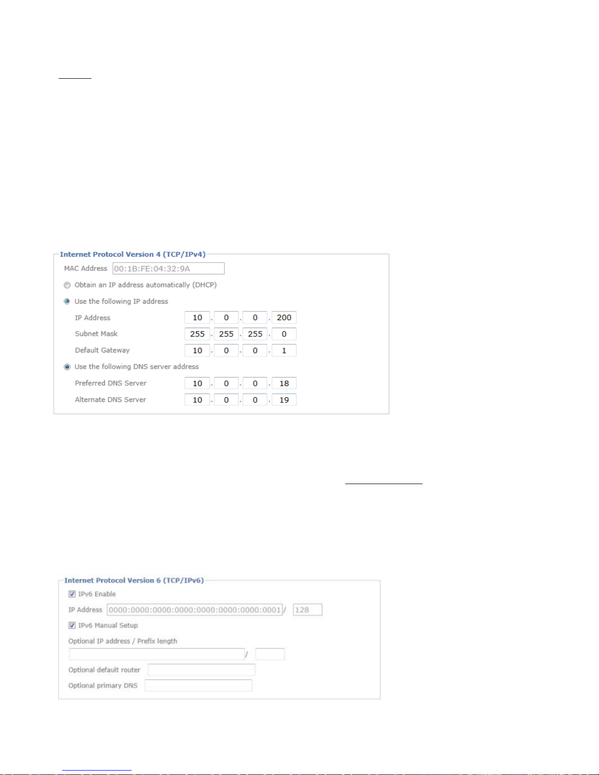
Network………………………………………………………………...………………………………………9
Date Time………………………………………………………………………………….……………………12
Video…………………………………………………………………………………………………...………13
Audio…………………………………………………………………………………………………..……….15
Live View…………………………………………………………………………………………….……………16
Video……………………………………………………………………………………………….………...…16
Audio……………………………………………………………………………………………….…...………16
Camera Setting…………………………………………………………………………………….……....……16
Playback…………………………………………………………………………………….………………….…18
Network Storage………………………………………………………………………….……………………..18
Local Storage…………………………………………………………………………….………………..….…18
Event………………………………………………………………………………….……………………….…..18
Event Server…………………………………………………………………………….………………..….….18
Event List………………………………………………………………………….………………..…………..19
Motion Detection………………………………………………………………….…………….…...……….…20
Tampering Detection……………………………………………………………….…………….…..…….…...20
Schedule………………………………………………………………………….……………………….…….20
System…………………………………………………………………………………….………………….……21
Maintenance…………………………………………………………………………………………….…...….21
Date Time…………………………………………………………………………………………….…………21
Security……………………………………………………………………………………………….…………21
Network Basic………………………………………………………………………………………….……….22
Network Advanced………………………………………………………………..…………………….………22
Digital I/O…………………………………………………………..………………………………..….………24
LED………………………………………………………………..………………………………...………….24
System Log…………………………………………………………………………..…………….……………24
1

User
Manual
Safety Instruction
Before you use this product
This product has been designed with safety in mind. However, the electrical products can cause fires which
may lead to serious body injury if it is not used properly. To avoid such accidents, be sure to heed the
following.
Legal Caution
Video and audio surveillance can be forbidden by laws that vary from country to country. Check the laws in
your local region before using this product for surveillance purposes.
Don't open the housing of the product
Don't try to open the housing or remove the covers which may expose yourself to dangerous voltage or other
hazards.
Don't use the accessories not recommend by the manufacturer
Heed the safety precautions
Be sure to follow the general safety precautions and the “Operation Notice.”
Operation Notice -Operating or storage location
Avoid operating or storing the camera in the following locations:
•Extremely hot or cold places
(Operating temperature: -10°C to +50 °C [14 °F to 122°F] )
•Exposed to direct sunlight for along time, or close to heating equipment (e.g., near heaters)
•Close to water (e.g.,near abathtub, kitchen sink, laundry tub)
•Close to sources of strong magnetism
•Close to sources of powerful electromagnetic radiation, such as radios or TV transmitters
•Locations subject to strong vibration or shock
In case of abreakdown
In case of system breakdown, discontinue use and contact your authorized dealer.
In case of abnormal operation
•If the unit emits smoke or an unusual smell.
2

•
If water or other foreign objects enter the cabinet.
•
If you drop the unit or damage the cabinet:1 Disconnect the cable and the connecting cables. 2Contact
your authorized dealer or the store where you purchased the product.
Transportation
When transporting the camera, repack it as originally packed at the factory or in materials of equal quality.
Ventilation
To prevent heat buildup, do not block air circulation around the device.
Cleaning
•
Use asoft, dry cloth to clean the external surfaces of the device. Stubborn stains can be removed using
asoft cloth dampened with asmall quantity of detergent solution, then wipe dry.
•
Do not use volatile solvents such as alcohol, benzene or thinners as they may damage the surface.
3

Minimum System Requirement & Product Feature
System
Requirement
For
normal
operation
and
viewing
of
the
network
camera,
it’s
recommended
that
your
system meet these minimum requirements for proper operation:
Note:
1. If using Windows 98 or Windows ME, please install IP Installer before using WEB UI to ensure the system
runs normally.
2. If not able to view the recorded video file, please install Xvid codec while installing Intelligent IP Installer.
(For Windows 98, ME or 2000 server, the codec might not work properly. Please download Xvid codec 1.0
from the internet.)
3. Please keep updating the latest Windows software and service package. (Ex: Net Framework, Windows
Media Player, Enhance ActiveX Security)
4
Item
Requirements
CPU
Minimum Intel® Core 2Duo or higher (Core i3 or above is
recommended)
Graphic Card
256 MB RAM graphic cards
(or equivalent on-board graphic cards)
RAM
Minimum 1GB of RAM (2GB or above is recommended)
Operating
System
Window 2000, 2003, XP, Vista or Windows 7
Mac OS Leopard 10.5
Web Browser
Internet Explorer 8or later

Product
Features
5
SYSTEM
Resolutions H.264/ Motion JPEG
Compressing format H.264/ Motion JPEG
Frame Rate Up to 20 fps at 2048 x 1536, up to 30 fps at 1920 x 1080
Image settings Rotation: Mirror, Flip, Mirror Flip
Brightness / Contrast / Saturation/ Sharpness
Overlay capabilities: time, date, text and privacy image
Image snapshot Yes
Video Recording Yes
Full Screen Viewing Yes
Digital Zoom 10x digital
Mobile Phone Live
View
Through 2.5 WAP(above 3G is recommended)
Alarm Sending Network storage/ FTP/ SMTP/ HTTP event
Security Password Protection / HTTPS encryption / IP Filter
Alarm Buffer
Input: alarm buffer, motion detection, audio detection
Output: network storage, FTP, SMTP, Pre-and post alarm buffer
Supported protocols Bonjour, TCP/ IP, DHCP, DNS, DynDNS, PPPoE, ARP, ICMP, FTP,
SMTP, NTP, UPnP, RTSP, RTP, RTCP, HTTP, HTTPS, SSL, TCP,
UDP, ISMA
Simultaneous
Connection
Up to 10 users
Operating conditions -10℃~ 50℃(14℉~ 122℉)
HARDWARE
Lens Ø 14 Varifocal Board lens
Local Storage Support MicroSD/ SDHC card
Power 12V DC, Power comsumption: Max. 8W
NETWORK
Ethernet 10/ 100 Base T

Main Page
Toolbar
of
Main
Page
Icon
Function Instruction
Home Click this tab to return to the page of live view.
Setting Click this tab leads to set up all the configuration.
Pause
Click this tab to hold the current video stream for a moment.
Stop
Click this tab could stop the video being displaying.
Recording
This tab is used to record the current video stream, it turns red when
starting to record. The video would be filed by the current date and
can be saved at anywhere you want to place.
Snapshot
This tab is used to take a snapshot of the current image.
The image can be saved at anywhere you want to place.
Sound This is listen tab, click on it switches to the mute mode.
Use the slider to control the volume.
Talk This is talk tab, click on it switches to the mute mode.
Use the slider to control the volume.
Zoom
Click this tab to adjust the digital zoom range.
Full screen
Click this tab to stretch the view to the entire screen. Press the ESC
on the computer keyboard to cancel the full screen.
6

7
Client Setting
Profile
Click the drop-down menu to choose video compression mode of Live
View among H.264 and MJPEG.
Note: As long as the operating system is not able to afford loading under
H.264 mode, please downgrade the mode to MJPEG.
View Size Select the desired view size of image resolution between Fit Screen
and Full Screen.
Protocol Select the transferring protocol among TCP, UDP, and HTTP.

Basic Setup
Account
Account List
The device default account and password setting is “admin /admin”. That means everyone who knows IP
address can access the device including all configuration. It is necessary to create anew password if the device
is intended to be accessed by specific ones.
Click “Add” to create the accounts to the specific users. There are 1default account and 9accounts that you
may assign 3different viewer modes as you wish. The instruction of 3viewer modes listed as below:
Anonymous Setting
There is adrop-down menu for Anonymous viewer to disable or enable the function.
8
Viewer It only allows the user to access to the Live View page.
Operator
It allows to view the Live View page, create and modify events, and adjust certain other settings.
Administrator
It allows the user to watch the live view and access all configurations.

Network
TCP/IP
Internet Protocol Version 4(TCP/IPv4)
Obtain an IP address automatically (DHCP):If aDHCP server is installed on the network, to select this
while the IP address is assigned by the DHCP server.
Use the following IP address:Select this option when the fixed IP address is set.
IP address: Enter the IP address of the device.
Subnet mask: Enter the subnet mask.
Default gateway: Enter the default gateway.
Obtain DNS server address automatically:Select this to obtain the address of DNS server automatically.
Use the following DNS server address:Select this when you set the fixed address as the IP address of
DNS server.
Preferred DNS server: Enter the IP address of the primary DNS server.
Altenate DNS server: Enter the IP address of the secondary DNS server, if necessary.
Internet Protocol Version 6(TCP/IPv6)
9

IPv6 Enable
When IPv6 is enabled, your IP Camera will receive an IP address which is assigned by network router under default
seeting.
IPv6 Manual Setup
If DHCPv6 server and relative router aren’t available on your network system, please select this opiton to set up
IPv6 manually. The following blanks will be displayed for you to enter the corresponding information when you
choose this item.
HTTP
HTTP port number:Select 80 in general situations. If you want to use aport number other than 80,
select the text box and enter aport number between 1124 and 65534.
When you have set the HTTP port number to anumber other than 80 on the Network Setting screen
in the Setup Program, access the device by typing the IP address of the device on the web browser as
follows: Example: when HTTP port number is set to 2000 http://192.168.1.100:2000/
Note:Reboot the IP Camera after the network setting has been made.
Note:If you connect the IP Camera with your computer directly, the default network domain of
camera is 192.168.1.xx
PPPoE
If your ISP provides Dynamic IP with authentication by username and password, type all PPPoE information in
this part. When using the PPPoE function, you need to turn on the DDNS or IP Notification function at the same
time.
10

IP address:The IP address obtained at the PPPoE connecting with network.
User ID:Enter the user ID for authentication necessary for PPPoE connections. Type it up to 64 characters.
Password:Enter the password for authentication necessary for PPPoE connections. Type it up to 32 characters.
Re-type password:Re-type the password to confirm.
Obtain DNS server address automatically:Select this to obtain the address of DNS server automatically.
Use the following DNS server address: Select this when you set the fixed address as the IP address of
DNS server.
Preferred DNS server: Enter the IP address of the primary DNS server.
Alternate DNS server: Enter the IP address of the secondary DNS server.
Note :
1. PPPoE (Point-to-Point Protocol over Ethernet): PPPoE is anetwork protocol for encapsulating
Point-to-Point Protocol frames insider Ethernet frames. PPPoE connection is used mainly with ADSL
service where individual users connect to the ADSL transceiver (modem) over Ethernet work. It also
widely used in XDSL (digital affiliate line such as ADSL, VDSL or SDSL)
2. Reboot the IP Camera after the network setting has been made.
3. The IP Camera with Intelligent IP Installer can’t be founded after turning on the PPPoE and reboot.
11

Date Time
Current Date /Time
It displays current time and date of IP Camera and PC that you connected, and you may select the Date/Time
format as you wish in the drop-down menu.
Note: If you would like the Date /Time information shows on the Live View screen, please check “Basic Setup
→Video →Overlay →Overlay Type →Time Stamp ”and save the setting.
Synchronization Method
Keep current setting: Select this mode to keep the current date and time of this IP Camera.
Synchronize with Client PC: Select this mode to keep the date and time of this IP Camera is the same
as the monitoring PC.
Manual setting: Select this mode to adjust manually the date and time of this IP Camera.
Synchronize with NTP: Specify the NTP server name and click “Update now” to synchronize the date and
time of this IP Camera with those of the time server, known as the NTP server.
Time Zone
Time Zone: Select the Time Zone format of Greenwich Mean Time among different cities. The time display
will be the same as the current date / time option.
Daylight Saving Time: There are two modes to choose for setting up daylight saving time.
By Date: Set the start and end time by select month, day, hour, and minute.
By Week Number: Set the start and end time by select month, week, hour, and minute.
Note: The NTPserver (Network Time Protocol) is the time server which is an Internet standard
protocol built on the top of TCP / IP. This assures accurate synchronization to the millisecond of
computer clock times in a network of computers.
12

Video
Video Setting
Image
Image Rotated: Select the screen display “flip”, “mirror”, or “mirror + flip”.
Video clip format: Select RECORDING compression format H.264 or MJPEG.
H.264: H.264 can decrease the bandwidth usage and further apply on 3G. We support High, Main and
Baseline, three H.264 profiles. In the same video quality, High profile provides higher compression than other
two, but needs more processing power to decode.
MJPEG: Motion JPEG stream uses considerable amounts of bandwidth, but provides excellent image
quality and access to every image contained in the stream.
Capture mode: You may choose the mode of 20fps at 2048x1536 or 30fps at 1920x1080. When you change
the capture mode, the system will reboot for once.
Overlay
Text information can be showed on the display screen, such as Date /Time and the user-defined title.
Privacy Mask
Privacy Mask is an area of solid color that bans users from viewing part of monitored area.
13

Click “Add” and asetting pop-up window comes out. Atranslucent rectangle is located at up left of the image,
drag it to where you wish to cover and resize it. Enter adescriptive name, select the color and enable it then
save.
Profile
There are five stream profiles available for quick set-up. These settings can be adjusted and new customized
profiles can be created. Each profile has a descriptive name, describing its usage and/or purpose. The profiles
can be selected from the Live View page.
Create anew stream profile: Click “Add” and asetting pop-up window comes out.
Edit the stream profile: Click the profile you appoint to modify and click “Edit”to do the further setting.
14

Day/Night
IR
Cut
Filter
Mode:
There are 4modes for IR cut filter to switch Auto, Night Mode, Day Mode, Schedule to
make IR cut filter work based on different conditions.
IR
Cut
Filter
Switch
Delay:
This is interval time(by seconds) when the IR cut filter switch has been
implemented till it indeed works.
IR Cut Filter Threshold: Dark- This is the threshold for the IR cut filter image environment being bright
turning to dark. Bright- This is the threshold for the IR cut filter image environment being dark turing to bright.
IR Mode: Select one among four modes --- auto / active / inactive / schedule. It decides IR working condition.
IR Level (Spot/ Wide):The strength of IR light can be adjusted upon application environment.
Audio
Audio Input
Select the external microphone input gain value you wish in the drop-down menu, and based on your region to
select the proper codec and save all settings.
G.711 U-law : one codec for “Computer Audio”, used in North America & Japan areas.
G.711 A-law : another codec for “Computer Audio”, used in Europe and the rest of the world.
Audio Output
Select the external speaker output gain value you wish in the drop-down menu and save it.
15

Live View
Video
Please refer to p.13
Audio
Please refer to p.15
Camera
Setting
Image Setting
Image Enhancement
Brightness:The image brightness can be adjusted in the range 0-100, the ahigher value produces a
brighter image.
Saturation:Adjust the saturation in the range 0-100, the higher value gets more colorful image.
Contrast:Adjust the image's contrast by raising or lowering the value in the range 0-100.
Sharpness:Controls the sharpness applied to the image in the range 0-100. Asharper image might
increase image noise especially in low light conditions. Alower setting reduces image noise, but the
image would be less sharp.
White Balance
Color Tone:The color tone can be adjusted in the range -127 to 127, it depends on individual preference to
select.
Auto White Balance:This is used to adjust for the different colors present in different light sources, to
make the colors in the image appear the same. The IP camera can be set to automatically identify the light
source and compensate for its color. Alternatively, the type of light source can be manually selected from the
drop-down menu.
Exposure Setting
Exposure Frequency:The default setting of lighting environment is Auto.However, you may select
50 or 60 Hz upon the lighting environment of your country. The hold current option fixes the current
exposure settings.
Automatic exposure:You can manually set the exposure value, which ranges from 0-100(dark to bright).
Exposure time:Select aproper exposure time according to the light source of the surroundings. The
exposure times are selectable from 1/2second to 1/10000 second. Shorter exposure time brings less light.
Gain:According to the surroundings in the low light and make the range among 1x-16x. The higher
value makes brighter image, however brings more noise at the same time.
16

Low light behavior:This is the operation aims at low light and night mode. According to the
surroundings you can manually set the preferable settings differ from the regular “Exposure Settings”.
Nevertheless, the low light behavior can be scheduled up by working day,weekend,and night mode
as user’s preference.
Backlight
Compensation
:It makes the object clearer display when the image background is too bright
or the object is too dark.
Iris Control
User may manually turn on the iris control or set it to auto.
Wide Dynamic Range
Enable Wide Dynamic Range auto to improve the exposure when both bright and dark areas simultaneously
in the field of view of the camera. Select mode ON to manual the level which goes from 0-255, the larger
number brings stronger influence, and the default is off.
Noise Reduction
Select the period you wish the noise reduction being executed in the drop-down menu, there are working day,
weekend,and night mode. The range of noise reduction is 0~35, and the default setting is auto with level 15.
17

Playb
ack
Network
Storage
Network storage provides the storage function for saving image files to the specified computer and folder
connected with the operating computer.
Before using this function you must go to Event
Server in Event to configure all settings and make the
recording file saved here.
Local
Storage
Memory
card
provides
local
storage
function
for
saving
image
files
to
the
specified
SD
card (for Class 4
or above)
in
your camera. This function can be enabled only when you insert SD card to the camera, and the
SD/SDHC card works well.
Before using this function you must go to SD card in Event to configure all settings and make the recording
file saved here.
Event
Event
Server
Event Server
Click “Add” to create aevent server then the setting page pops up. Name it, select your network type put on the
storage location. This is optional to create the password for certain group to use it. Then click the “Test”button
to see if it works, it will show the information on the pop-up window to see your setting if has been made
successfully.
We offer Snapshot and Video two types of event transmission to select. When you choose Snapshot, there is a
range 0~7 seconds can be selected individually for pre-event and post-event. Two suffix options for naming image
file by None and Date Time.
18

SD Card
Make sure to insert the SD Card first then click “on”. Create afolder name for event server in SD Card.
Optional selection for overwrite the previous file or not, if not, you may set awarning when the capacity below
the following percentage:5%, 10%, 25% and 50%.
Event
List
Event List
General
Name the event file and make it on or off.
Trigger
You may activate the following trigger types as you wish depends on various conditions:
Motion Detection:Click it on for using Motion Detection function as asensor. You must configure
motion detection function before taking this as the trigger. Set minimum time interval between 2 triggers,
and choose the desired detection area. The detection type individually stands for the following meanings :
Start:The trigger would be activated when the target object starts to move.
Stop:The trigger would be activated when the target object stops to move.
Tampering Detection:
This setting is set for the trigger will be started for the duration of tampering lasts you configure. The
Duration range is from 5 seconds to 900 seconds.
Digital Input:
This can be set to control the external alarm input of I/O port on the rear of the device to start the trigger.
Periodical:
This can be set the certain period(by minute) to start the trigge.
Action
There are three choices for action taking which is optional for user to select all of them or part of them:
Send Image、Send Notification and Activate Digital Output.
Send Image: You may set up where the image sent to, options like event server and SD card. You must
configure it first, please refer to Event Server.
Send Notification:Firstly go to HTTP server configure the HTTP server URL, port, User ID, Password, and Proxy
server settings.
Note: The Setting of URL should be the same as CGI.
Activate Digital Output:Choose this option to enable the external digital output device when a trigger is
triggered.
19
Table of contents
Other Zavig IP Camera manuals