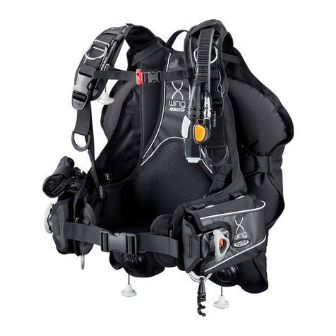
Zeagle Buoyancy Compensator User manual

Buoyancy Com pen sa tor
Owner’s Man u al

Introduction
1
Thanks for Choosing Zeagle!
We value your decision to invest in a Zeagle Buoyancy Control
System. Please have your authorized Zeagle Dealer familiarize you with
the operation and care of your new Zeagle Buoyancy Compensator*
(BC) and go over your Owner’s Manual with you. Have your Dealer sign
the appropriate line on the service record at the end of this manual, after
he has performed this service. Before you use your BC for the first time,
be sure your Dealer has performed the Dealer prep check list. Please
save and refer to this Owner’s Manual from time to time to enable you to
fully understand and benefit from this fine product.
SCUBA Diving is an extremely enjoyable pastime when done
with proper training, good equipment, and knowledge of both your equip-
ment and your diving environment. This Zeagle Buoyancy Control
System is intended for use only by individuals practicing safe div-
ing principles.
*Buoyancy Compensator (BC) and Buoyancy Control Device (BCD)
are synonymous for the same piece of SCUBA diving equipment.

Contents
2
Introduction .................................................................. 1
Warranty Information .................................................... 3
General Information and Specifications ...................... 4
Function of the Zeagle System ..................................... 7
Fitting and Assembly ................................................... 9
Double Tank Mounting Options .................................. 12
Pre-dive Assembly and Inspection ...............................15
Donning Procedures .....................................................19
Diving with the Zeagle System .....................................20
Emergency Procedures ................................................21
Maintenance .................................................................23
Available BCD Accessories ..........................................24
Service Record ............................................................25

3
Warranty Information
LIMITED LIFETIME GUARANTEE TO THE
ORIGINAL OWNER
Your BC is guaranteed against defects in materials and workman-
ship. This guarantee does not cover damages from accident,
abuse, neglect, alterations, improper usage, normal wear & tear or
failure to provide reasonable care. To validate your warranty you
must fill out and return your warranty registration by regular mail
or e-mail, within 30 days of purchase. All warranty claims will be
handled through Zeagle, or an authorized Zeagle Dealer.
Owner’s Responsibilities
• Zeagle Systems, Inc. requires that the end user of this system be
certified by a nationally or internationally recognized SCUBA certific-
ation agency and adequately trained in its use by a certified SCUBA
instructor with thorough knowledge and experience in the use of
Zeagle Systems, Inc. equipment.
• An annual inspection performed by an authorized Zeagle Dealer is
required for the safe operation of this system.
• Your Zeagle BC is NOT a personal flotation device and should
not be used as a life jacket. The BC does NOT guarantee a
heads up position of the wearer at the surface.
• All emergency procedures should be practiced periodically in shal-
low water (10 feet or 3 m) to maintain preparedness in the event an
actual emergency should occur.
• The owner is ultimately responsible for completing the Warranty
Registration by filling out the form included with the BCD and mailing
it to Zeagle Systems, Inc., or by going to the Product Registration
page at www.zeagle.com. One of these methods must be completed
within 30 days of purchase.
• For assistance with preparation, questions or service, contact your
local authorized Zeagle Dealer or Zeagle Systems, Inc.

4
General Information and Specifications
This Buoyancy Compensator's Owner's Manual contains
important safety, maintenance, and operation information.
Read this manual thoroughly before diving.
Important information on the assembly, operation, and mainte-
nance of your BC is designated throughout this manual with the
"IMPORTANT" graphic and the symbol shown above.
This owner's manual also uses the following "WARNING"
graphic and symbol to designate that special attention needs to
be given to the manual, otherwise, a potentially hazardous situa-
tion which, if not avoided, may result in injury or death.
SCUBA diving is an adventuresome activity and some risks
are involved. Please be sure that you and your dive partner
have current certifications and follow all of the recommend-
ations of your certifying agency and that all equipment
is used and maintained according to the manufacturer’s
recommendations. Failure to follow these guidelines can
result in serious injury or death.

Tank Pictogram
19 XX
MAX liters
5
General Information & Specifications
SCUBA Cylinder Selection and Configuration
The maximum single and double cylinder size specifications (in liters) for
the BC is found on a tank pictogram on the warning label. This label is
found on the BC, inside the vest. If the double cylinder pictogram has a
"XX" in it, then the BC has been designed for single cylinder use only. If
the single and double cylinder pictograms have numbers in them, then
the BC has been designed for either single or double cylinder use. The
number in the pictogram indicates the largest cylinder size recommend-
ed, in liters.
Cylinder capacity is the volume of the SCUBA cylinder. When ex-
pressed in cubic feet, the volume is given for compressed gas. When
expressed in liters, the volume is given for the actual volume of the
cylinder based on the interior dimensions of the cylinder (water capac-
ity). Zeagle Systems, Inc. maximum recommended cylinder capacity is
120 ft3 (19 liters). Once again, if you have a question, consult your local
authorized Zeagle Dealer.
Failure to comply with the following information may result in an im-
proper buoyancy configuration. You must maintain neutral buoyancy
while diving to prevent injury or death.
Your over-all buoyancy depends on a combination of the buoyancy of all
your diving equipment added to your own body's buoyancy. The Zeagle
System is designed to work with a variety of tank sizes and configura-
tions.
Cylinder dimensions and capacity are two quantities
which are important to understand when configuring
your equipment. Cylinder dimensions are the actual,
outside dimensions of a SCUBA cylinder (also called
the tank). Zeagle BC's are designed specifically for
SCUBA cylinders which have a maximum diameter
of 8 in (20.3 cm) and maximum height of 31 in (78.7
cm). Consult your local authorized Zeagle Dealer if
you have any questions regarding cylinder dimen-
sions.

6
General Information and Specifications
Operating Temperature Range
Table 1.0
180 N
(rounded down to nearest 10 N)
prEN1809
44 lbs / 19 kg
BUOYANCY
Total
Air -4o to +122o F -20o to +50o C
Water +28o to +104o F - 2o to +40o C
Surface Buoyancy of BC's
Your BC's buoyancy, has been rated by Zeagle Systems, Inc. Buoyancy
figures were measured in fresh water at sea level, and were rounded
down to the nearest pound. For buoyancies listed in the metric system,
buoyancy is measured in multiples of 10 Newtons, then rounded down to
the next lowest multiple.
The buoyancy of your BC is printed on a label, located on the bladder
assembly, as shown on page 8. A typical label for a BC will look like the
example below. This particular label indicates that the bladder assembly
is rated at 19 kg (44 lbs) buoyancy.
Special Instruction in cold water diving methods, and the specific
use of this product is required prior to cold water diving (tempera-
tures below 10o C / 50o F). This instruction is beyond the scope of
this Owner's Manual. Diving without this instruction could result in
injury or death. Consult your SCUBA instructor for this instruction
prior to using this product in cold water.
Shelf Life
The shelf life for a new, unused BC when deflated and stored in a dry
place at room temperature, with no exposure to ulraviolet (UV), light is
seven years. Refer to page 23 for Storage and Post Dive BC Cleaning
information.

7
Function of the Zeagle System
The Zeagle Buoyancy Control System
The function of the Zeagle buoyancy control system is to add to your
diving enjoyment. It is designed to provide you with a comfortable way
of “wearing” your SCUBA system, a resting platform while on the surface,
and an easy means of controlling your buoyancy while diving.
Vest
The vest portion of the system should fit so that it wraps partially around
the front of the diver. See the Illustration on page 14. You should be able
to tighten the waist strap so that the vest fits quite snugly around the
waist, in order to prevent the BC from shifting during the dive. If you can
draw the two sides of the vest together and the fit is still not snug, you
need a smaller size vest. If the Vest is uncomfortably tight when the fully
extended strap is fastened, you need at larger vest. The ZENA lady's
BCD is different from other models, in that the vest portion is fastened to
the body of the BCD with two adjustable straps and is closed by a front
zipper. The ZENA is worn so that the top strap is at the narrowest part of
the waist, above the hips.
Side Panels (Cummerbund)
The side panels should fit around the waist (top of the hip) NOT over
your rib cage or diaphragm, with at least a four inch overlap on the touch
fastener (Velcro) closure. The side panels are attached using six (6)
plastic screw fasteners, and can be adjusted by moving the side panels
to a different set of grommets on the vest section. See the Illustration
on page 9. It is imperative that the BC not be worn too high on the
body as this will create an undesirably high center of gravity and could
restrict the ability of your diaphragm to move freely, resulting in discom-
fort or shortness of breath. Side Panel Extenders are available.
Shoulders
Length of the shoulder strap depends on personal comfort and the length
of your torso. Take into consideration different suits you may be wear-
ing with the system, and be sure to allow enough length so the pack
may be worn low as described above. The sternum strap should be just
above the breast line as shown on page 14. You should easily be able to
reach the quick release buckles. The sternum straps have high and low
attachment loops. The BCD leaves the factory with the sternum straps
attached to the higher loops. If this position puts the strap too close to
the neck or the strap is covering a Dry Suit inflator, then the strap can be
moved to the lower attachment points.
8
Function of the Zeagle System
The Winglet Side Release Buckles
must be attached to the vest.
Surface Buoyancy
Label Location
Do NOT dive with the two winglet side release buckles detached!
Bladder Assembly
The bladder assembly attaches to the vest section via four stainless
steel slotted fasteners sewn to inner edge of the bladder assembly. Each
of these slotted fasteners slides over the two Single-Tank Bands. This
fastenes the Bladder to the Tank Bands. If the BC is to be used with
double tanks, then the single tank bands are removed and the optional
double tank straps (p/n 7281M) slide through the webbing slots at the
back of the vest just as the removed single tank bands did (see cylin-
der band illustration on pages 10 thru 13). The stamped metal ends of
the straps are threaded through the eye of the metal tabs on the Blad-
der Cover (see illustration below). There are two plastic buckles on the
Bladder Cover Winglets, which clip over the weight pockets to hold the
buoyancy forward. Do not dive with the two forward small side release
buckles detached! The shoulder straps should pass through the collar
at the top of the bladder assembly.
Shoulder strap goes
through the collar
The Tank Bands and the optional dou-
ble tank straps go through the same
backplate webbing slots.
Optional double-tank Straps are
required IF Double Tanks are
mounted to the BC.
p/n 7281M (2 required)

9
Adjusting the Side Panels
1. Using two coins, unscrew the plastic barrel-screw fasteners.
2. Move the side panel to different set of grommets on vest and re in stall.
Fitting and Assembly
3. Note that one extra plastic barrel-screw is installed in an unused
grommet hole when the BCD leaves the factory. This extra screw can be
used if one is lost.
NEVER breathe from the bladder assembly. The bladder as-
sem bly was not designed as an auxiliary air source and may
contain harm ful con tam i nants, which if inhaled, may cause
in ju ry or death.

10
Illustration “A”
Non-Slip Plate
(Standard System Only)
(Single Cylinder Band Assembly)
Fitting and As sem bly
Illustration “B”
Threading The Stan dard
Single Cylinder System
Note: Tank bands expand and lengthen when wet. For this reason, you will get a tighter
fi t if you make your initial adjustments with tank bands that have been wet for at least 20
minutes.
1. Thread the lower cylinder band through the non-slip plate and then under the bottom
. center backplate straps as shown in Illustration “A.”
2. Thread the upper cylinder band under the top center backplate straps on BC as shown
. in "A".
3. After threading the bands through the BC, thread the bands through the buckle as per
. Illustration “B”.
4. Threading instructions are also embossed on the side of the plastic buckle.
5. After Looping the webbing through fi nal slot in buckle, check to be sure that your
. cylinder is lined vertically on the BC. “Cam” the buckle over for extra tension.
6. Lock the buckle by engaging the Velcro material on the tank band.

11
There are only minor differences on a twin cylinder model. The rubber
“non slip” plate should be completely installed on the bottom band oppo-
site the touch fastener (Velcro) material on the band, before inserting the
band under the webbing on the pack. The bands go under the vertical
webbing on the back plate. If your system has only two pieces of vertical
webbing, it is not a twin cylinder model and should not be used with twin
cylinders. If you are setting up a double pack for single cylinders, please
note that the single size cylinder bands only go under the center 4 inches
(10.2 cm) of vertical webbing on the back plate and the rubber plate is
installed as illustrated on pages 10 and 12.
Threading The Standard & Quick Release
System On A Twin Cylinder Back Plate
Fitting and Assembly
Standard System
Optional Quick Release System
• An alternate method of attaching twin cylinders with steel bands is by bolting
through the back plate grommets.
• Optional band extension used only with quick release band for twin cylinder use.
• Extension strap should be adjusted at cylinder buckle hook end for proper cylinder
size.
Back Plate Grommets
Optional Band Extension

12
Quick Release fully closed
Fitting and Assembly
Mounting Optional Backplate for use with Double Tanks
Backplate Available in: Black Anodized Aluminum p/n 519-BP01A
Stainless Steel p/n 519-BP01S
Titanium p/n 519-BP01T
For Ranger, Ranger LTD, Tec,
Tec-Pac, 911 and SAR BCDs.
May require modification of
built-in Lumbar Pads.

13
Optional Double Tank Bands and Mounting Systems
For Ranger, Ranger
LTD, Tec, Tec-Pac,
911 and SAR BCDs.

14
Proper Fit
The Zeagle Personal Fit System allows the diver to size each component
of the buoyancy system independently, for a true custom fit. For proper
performance, please be sure that your system fits as described below.
Put the BC on (before attaching it to a SCUBA cylinder) and adjust the
shoulders and waist as follows.
1. Loosen the shoulder straps before
donning. Put it on like you would a
jacket. If your system is equipped with
cummerbund side panels, stretch the
elastic by extending each side panel as
far as possible before wrapping it around
you and fastening the Velcro.
3. Fasten the sternum strap. It should
be just above the breast line. If you
are wearing a dry suit, be sure that the
sternum strap does not obstruct the
drysuit inflator hose or valve. There are
two sets of loops for the sternum strap.
If the sternum strap is too high, the strap
can be moved to the lower loops.
2. The system should be worn low with
the bottom of the vest at the top of your
hips. Once the cummerbund side panels
are secure, fasten the waist strap and
tighten it snugly.
4. Adjust the shoulder straps.
Fitting and Assembly

15
Adjust the BC so that it does not restrict your breathing. Restriction of nor-
mal breathing while wearing your BC could result in injury or death. Before
each dive, check all bands, straps, clips, and/or waist panels for proper
adjustment.
Pre-dive Assembly and Inspection
Over Pressure Valve (OPV)
The over pressure / dump valve is typically located on the lower front of
the bladder assembly. Some models have two OP Valves. As its name
implies, the OP Valve prevents over inflation of the bladder. The valve
automatically releases air when the internal bladder pressure exceeds
the valve's spring pressure. The valve will automatically close when the
internal bladder pressure becomes less than the valve's spring pressure.
This valve may also be used to "dump" air when you are diving, by pull-
ing the knob / string that is attached to the valve. The OP Valve should
be inspected before every dive for proper operation.
Remote Exhaust Valve (RE Valve)
Your BC may be equipped with a remote exhaust valve. If it is, it is
located on the upper left, just behind the shoulder, on the bladder assem-
bly. The RE Valve allows you to "dump" or exhaust air manually as you
adjust for neutral buoyancy. The RE Valve operates by simply pulling on
the power inflator mechanism and corrugated rubber hose.
The RE Valve should be inspected before every dive for proper op-
eration. Also, inspect that both threaded caps on the RE Valve, are
tightened securely. The exhaust cap must be tightened a minimum
1/12 turn (3/8 inch) after it first contacts the body. The RE Valve was
designed to be serviced. Without proper tightening of these caps,
they may loosen over time and be lost.
Power Inflator/ Oral Inflator Mechanism
Your BC may also be equipped with a power inflator/oral inflator mecha-
nism. This unit consists of an Oral Valve Mouthpiece, Oral Valve But-
ton, and Pneumatic Inflation Valve (PIV) and connects directly to the
RE Valve via a steel cable (inside the corrugated hose). The PIV oper-
ates over a pressure range of 6.5-13.8 bar (95-200 psi). To inflate the
BC using the PIV, attach a low pressure hose to the quick disconnect
(QD) fitting and depress the PIV button. To inflate the BC using the oral
inflator, depress the Oral Valve Dump Button and breathe into the Oral
Valve Mouthpiece.
CHECK ALL MECHANISMS BEFORE EVERY DIVE FOR
PROPER OPERATION AND LEAKS.

16
Pre-dive Assembly and Inspection
Weight System Inspection
Check to see that weight release system is secure.
Ripcord ™ release system - check bottom of weight pockets to be sure
they are held closed by the ripcord. If the Ripcord has been pulled, re-
thread the system. (Refer to the re-threading section on following page).
Check to see that weight release system is secure.
ZIP Touch™ fastener pocket system - Check to see that the Velcro
touch fastener material fl ap on the bottom of each weight pocket com-
plete ly overlaps and is secure.

17
Pre-dive Assembly and Inspection
• Return the Ripcord handle to the secure position.
• Pull the cord through for the right side weight pocket.
• Start with the loop closest to the Ripcord handle.
• Each white nylon loop is threaded through three grommets. The
cord is then threaded through the end of the white loop.
• Thread the cord under the webbing that is between the grommets.
• Repeat for all nylon loops.
• Finish by pushing the cord between the pocket and the vest.
• Repeat on the opposite pocket.
Cord
If the Ripcord is not completely secure, re-thread using the following
procedure.
Nylon Loops
Cord
Re-threading The RipcordTM System
Check to see that weight release system is secure.
Trim Weight™, Pull-Out Pocket ™ Velcro Touch Fastener System
- Check to see that the touch fastener material fl ap on the bottom and
sides of each weight pocket completely overlaps and is secure.
Trim Weight™ Pull-Out™

18
Pre-dive Assembly and Inspection
Loading the Zeagle Integrated Weight System:
Weights can be loaded after the system is donned as shown, or the
weights can be loaded before the system is donned. Considerations in-
clude the amount of weight and the distance to enter the water. Ask your
buddy for help in either case. To load the weight system:
• Unfasten the buckles securing the bladder assembly winglets to the
side of the vest to allow easy access to the weight pockets.
• Load the Ripcord™ or Ziptouch™ pouches through the zippered
opening on the pocket top. Be sure the zipper is fully closed after
loading.
• Pull-Out™- load the pouch though the Velcro Touch Fastener open-
ing. Close the opening and load the pouch into pocket according to
illustration.
• Refasten the buckles securing the bladder winglets to the side of the
vest.
(Important! This is required for proper BC performance)
Pull-Out™
Zip Touch™
Ripcord™
Pocket Pouch
Pouch
Pocket Pocket
Pouch

19
Donning Procedure
Diving equipment is heavy! To avoid injury or fatigue and to
become familiar with each other's equipment, have your buddy
assist you! Take this opportunity to be sure your buddy under-
stands how your weight release works.
Be sure you have read and performed the Proper Fit page in the Fitting
and Assembly section of this manual first.
• Open the cylinder band buckles and loosen the bands.
• Align the system so that the top of the bladder assembly is even with
. the cylinder valve (slightly higher or lower may be required depending
. on the diver’s size and the type of tank, but this is a good starting .
. point).
• Make sure that the two sets of bands are in vertical alignment with .
. your tank and not twisted to one side.
• Pull the bands snug and close the buckles. Secure the loose end of
. the bands on the Velcro touch fastener.
• Connect the regulator to the cylinder valve and finish assembling the
. system per manufacturer’s instructions.
• Be sure you are familiar with the low pressure inflator system on . .
. your Zeagle BC. Inflate the system and check for leakage.
• Weights can be installed in the weight pockets before the BC is . .
. donned or after. It may be easier to add your weights after you have
. the system on to avoid lifting the tank and weights together. Con-. .
. siderations include the amount of weight and the distance to enter . .
. the water. Ask your buddy for help in either case.
• Loosen the shoulder straps.
• Have your buddy balance the system while you put it on like a . . .
. jacket.
• Remember, the system should be worn low with the bottom of the .
. vest at the top of your hips
• Fasten the side panels and/or the waist band.
Extend the cummerbund side panels as far as possible before wrap-
. ping them around your body. Be sure to get the waist tight.
• Fasten the sternum strap and adjust it. If you are wearing a drysuit,
. be sure that the sternum strap does not obstruct the drysuit inflator .
. hose or valve.
• Adjust the shoulder straps.
• Fasten the split saddle strap if your system is so equipped.
Table of contents
Other Zeagle Diving Instrument manuals

Zeagle
Zeagle Envoy Octo 320-3110 User manual

Zeagle
Zeagle Flathead VI User manual

Zeagle
Zeagle N2ition User manual

Zeagle
Zeagle 1BCD User manual

Zeagle
Zeagle OCTO+ MK2 User manual

Zeagle
Zeagle Octo-Z User manual

Zeagle
Zeagle Tiger performance T-310SSL User manual

Zeagle
Zeagle N2ition User manual

Zeagle
Zeagle N2iTion3 User manual

Zeagle
Zeagle Octo-Z 320-7200YL User manual