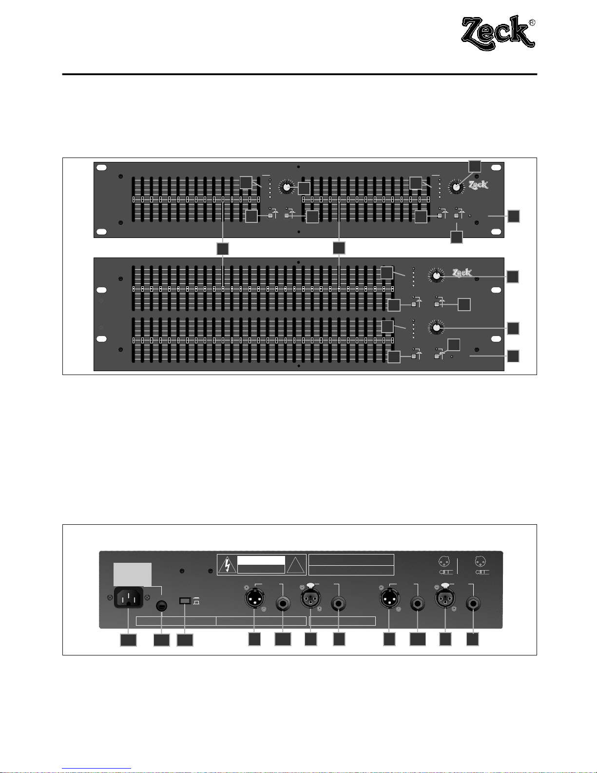
3. Bedienelemente
Die beiden Kanäle des GF Equalizers sind absolut identisch
und unabhängig voneinander ausgeführt. Die folgenden Erläu-
terungen beziehen sich daher nur auf einen Kanal.
EQ in
Zum Aktivieren des Equalizers muß sich der 'EQ in' Schalter in
eingerasteter Stellung befinden, was die rote Kontroll-LED
durch Leuchten anzeigt. Ist der Schalter nicht gedrückt, so
befindet sich der Equalizer im Bypass-Zustand (LED dunkel)
und alle Bedienelemente auf der Vorderseite sind deaktiviert.
Im Bypass-Zustand sind alle Ein- und Ausgänge des Gerätes
durch ein Ruhekontakt-Relais direkt miteinander verbunden, so
daß selbst bei Stromausfall keine Unterbrechung des Signal-
wegs eintritt.
'Gain' Regler und Aussteuerungsanzeige 'Headroom'
Das Eingangssignal des GF Equalizers gelangt zunächst in
eine Vorverstärker-Stufe, wo der Signalpegel mit Hilfe des
'Gain' Reglers verstärkt oder abgeschwächt werden kann. Die-
ser Regler ist nur bei aktivem Equalizer ('EQ in') aktiv. Befinden
sich alle Fader und der 'Gain' Regler in eingerasteter Mittelstel-
lung, so wird das Signal durch den Equalizer weder verstärkt
noch abgeschwächt und hat denselben Pegel wie bei nichtakti-
vem Equalizer (Bypass).
Die Aussteuerung des Signals kann mit Hilfe der 'Headroom'
Aussteuerungsanzeige kontrolliert werden. Diese Anzeige mit 5
LEDs zeigt nicht einfach nur den Eingangspegel an, sondern
berücksichtigt auch den jeweils maximalen Signalpegel inner-
halb der einzelnen Bandpaß-Filterstufen. Sobald ein Pegel an
einer Stelle im GF Equalizer den maximal zulässigen Spitzen-
wert überschreitet, leuchtet die 'Clip' LED rot auf. Die Zahlen
neben der 'Headroom' Anzeige zeigen die verbleibende Aus-
steuerungsreserve bis zum Übersteuern an.
Fader
Jeder Fader ist mit der ihm eigenen Regelfrequenz bezeichnet.
Durch Verstellen eines Faders wird aber nicht nur genau diese
Frequenz beeinflußt, sondern auch Frequenzen innerhalb eines
Bereichs ober- und unterhalb der Mittenfrequenz, genannt
Bandbreite. Diese Bandbreite ist für alle Fader konstant und
wurde so festgelegt, daß sich zwischen dem Bereich zweier
Fader ein optimaler Übergang ohne Einbrüche oder Spitzen im
Frequenzgang ergibt. Die Fader erlauben einen Einstellbereich
von ±12dB Verstärkung bzw. Abschwächung. Als Richtlinie ist
es hilfreich sich zu merken, daß eine Anhebung von 6dB eine
Verdoppelung und eine Abschwächung von 6dB eine Halbie-
rung des Pegels bedeuten. Der Pegel eines Eingangs-Sinus-
signals von 1kHz und 1Volt könnte somit mit Hilfe des 1kHz-
Faders zwischen 0.25V und 4Volt eingestellt werden, wobei
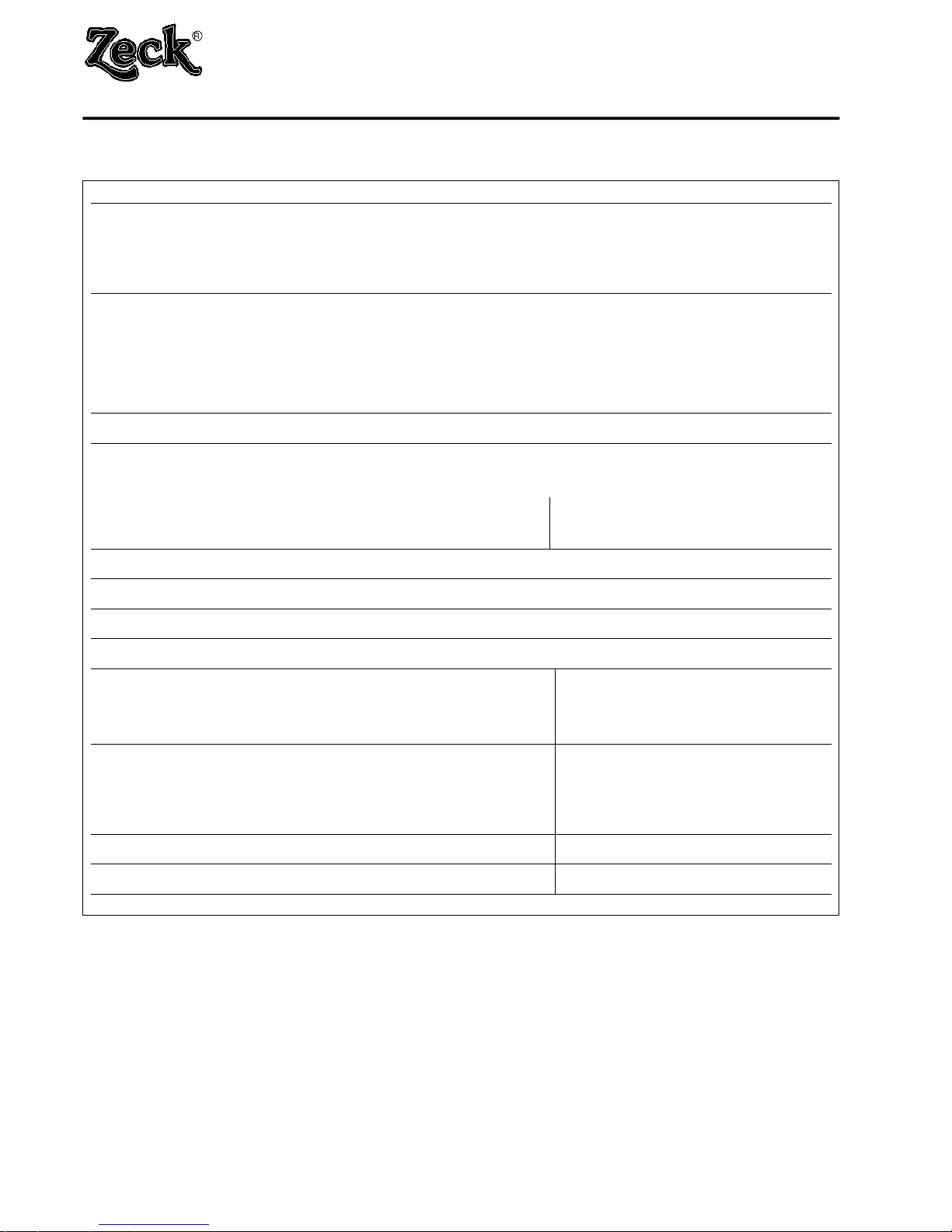
0dB 'keine Verstärkung' bedeutet. Die Nennfrequenzen der
Fader sind nach der ISO-Norm festgelegt, wobei der Abstand
zwischen zwei Faderfrequenzen beim GF215 2/3 einer Oktave
entspricht und beim GF230 1/3 einer Oktave. Die folgende
Tabelle zeigt den Zusammenhang zwischen den Nennfrequen-
zen der einzelnen Fader, den entsprechenden nächstliegenden
Musiknoten und dem Frequenzbereich:
GF 215 GF 230 Note
25 Hz 25 Hz G2
31 Hz H2
40 Hz 40 Hz D#1 Bass
50 Hz G1
63 Hz 63 Hz H1
80 Hz D#
100 Hz 100 Hz G
GF 215 GF 230 Note
125 Hz H
160 Hz 160 Hz d#
200Hz g tiefe Mitten
250 Hz 250 Hz h
315 Hz d#1
400 Hz 400 Hz g1
500 Hz h1
630 Hz 630 Hz d#2 Mitten
800 Hz g2
1 kHz 1 kHz h2
1.25 kHz d#3
1.6 kH 1.6 kHz g3
2 kHz h3
2.5 kHz 2.5 kHz d#4 Präsenz
3.15 kHz g4
4 kHz 4 kHz h4
5 kHz d#5
6.3 kHz 6.3 kHz g5
8 kHz h5
10 kHz 10 kHz d#6 Höhen
12.5 kHz g6
16 kHz 16 kHz h6
20 kHz d#7
Low Cut
Der 'Low cut' Schalter aktiviert ein internes Hochpaßfilter, das
alle Frequenzen unterhalb 40Hz mit einer Flankensteilheit von
18dB/Oktave abschneidet. Hierdurch hat man die Möglichkeit,
unerwünschte Tiefstfrequenzen von Beschallungsanlagen fern
zu halten.
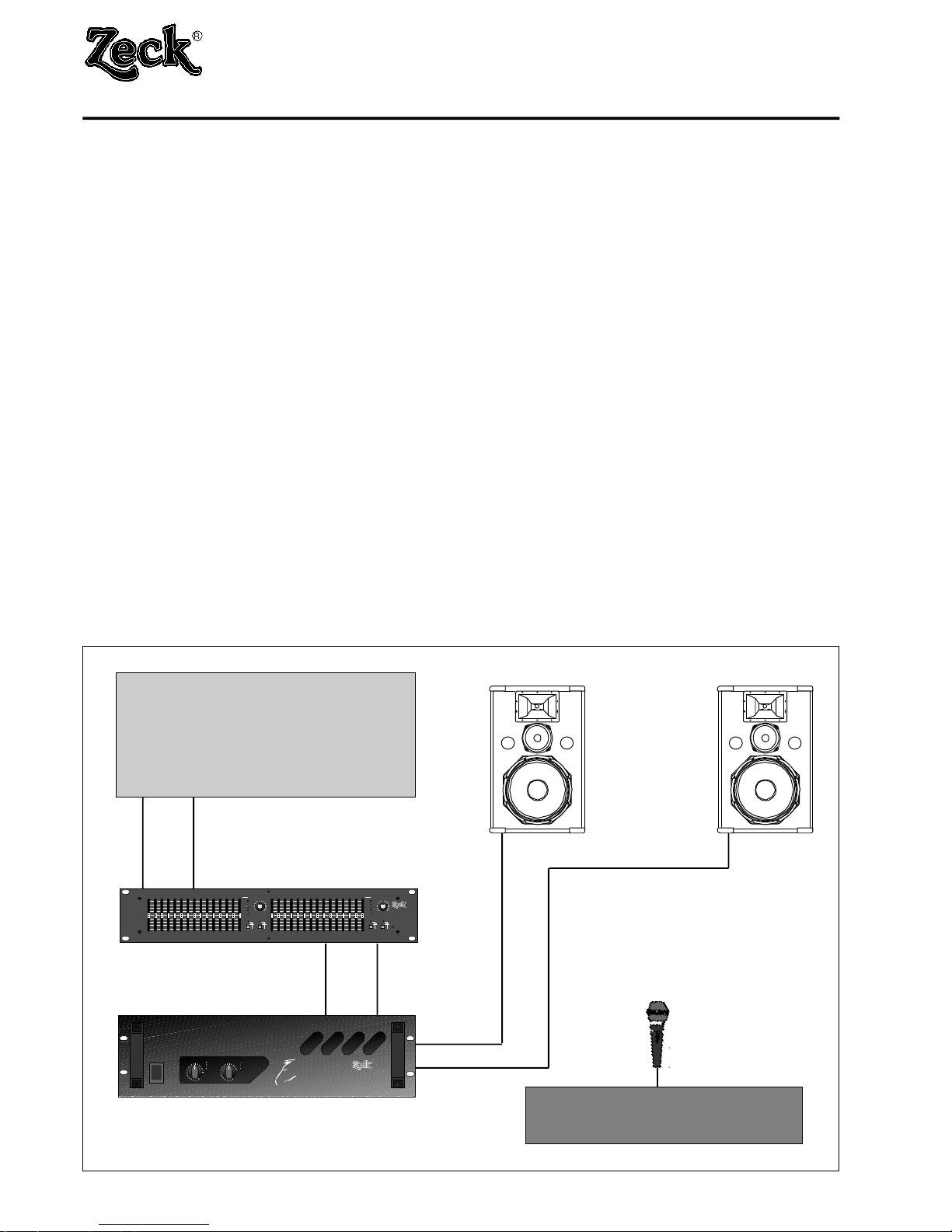
4. Benutzung des GF Equalizers
Was ist ein grafischer Equalizer ?
Die Bezeichnung Equalizer ('Angleicher'), oder kurz EQ, hat
ihren Ursprung in der Forderung, daß eine Beschallungsanlage
einen linearen Frequenzgang aufweisen soll, d.h. alle Frequen-
zen vom Zuhörer mit der gleichen Lautstärke empfunden wer-
den. Aus verschiedenen Gründen sind Beschallungsanlagen
alleine oft nicht in der Lage, dieser Forderung gerecht zu wer-
den, da sie ohne Korrekturmaßnahmen keinen linearen Fre-
quenzgang aufweisen. Ein graphischer Equalizer stellt ein sol-
ches Korrekturinstrument dar, mit dem die Lautstärke einzelner
Frequenzen verstärkt oder abgeschwächt werden kann. Dazu
wird das eintreffende Signal in mehrere (im Falle des GF 215 in
15 und beim GF 230 in 30) Frequenzbänder aufgeteilt, deren
individuelle Lautstärke durch die Fader eingestellt werden
kann. Die Fader zeigen hierbei durch ihre mechanische Stel-
lung den eingestellten Frequenzgang wie bei einer Grafik an,
daher der Ausdruck 'grafischer' Equalizer. Ein Equalizer kann
aber noch mehr als nur Frequenzgänge linearisieren: Auch zur
Feinabstimmung von Instrumentalklängen oder zur Rauschun-
terdrückung kann der GF Equalizer benutzt werden. Hierzu
werden unten noch weitere Anwendungsbeispiele gegeben.
Einstellen des 'Gain' Reglers
Sowohl der 'Gain' Regler als auch die Fader haben Einfluß auf
die Aussteuerungsanzeige des GF Equalizers, weshalb der
'Gain' Regler erst nach Erreichen einer endgültigen Einstellung
der Fader (s. unten) eingestellt werden sollte. Wird der Equali-
zer hinter einem Mischpult betrieben, so sollte zunächst auf
diesem das maximal zu erwartende Ausgangssignal eingestellt
werden und der 'Gain' Regler am Equalizer so eingestellt wer-
den, daß dessen 'Headroom' Anzeige ca. 3 bis 6dB Aussteue-
rungsreserve anzeigt. Nachdem am Equalizer der gewünschte
Frequenzgang eingestellt wurde, wird mit Hilfe des 'Gain' Reg-
owner's manual GF equalizers
7
owner`s manual GF equalizers © 1994 Zeck Audio