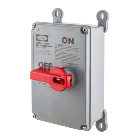
Zenith ZTSDH Series User manual

••
43R-50018
Revised March.
1996
\-
(
J721zENITHI
-
CONTROLS,
INC.
OPERATION
AND
MAINTENANCE
MANUAL
AUTOMATIC
TRANSFER
SWITCH
-
DELAYED
TRANSITION
(Mechanically
Held)
ZTSDH
SERIES
1600
THRU
3000.AMPS
...
MODEL
NUMBER
~~--~----------~1
<;ERIAL
NUMBERI
.__
--------------~1
ZENITH
CONTROLS.
INC...
830
W-.
40th St.. Chicago. IL
60609
(312)247-6400:
FAX.
{~12)247....:7805
. -

A.
POWER
PANEL
31
L
410£R
4C~C9
~
2091!
3061!
32
30~~
EL
~
307R
B. CONTROL PANEL
TORQUE
REQUIREMENTS
FOR
ELECTRICAL
CONNECTIONS TORQUE.REQUIREMENTS
FOR
FIE"LD
CONNECTIONS
All
current
carrying
parts
use
compression
washers
and
should
be
torqued
to
the
values
presented below.
Caution:
DO
NOT
OVER-
lORQUE
WASHERS; follow
the
given
torque
values.
Torque
Requirements
(inch-lb.
except
denoted
by
+
are
ft.-lb.)
Compression
Bolt Socket Set Washers
Size
Grade_5
Head Screw 1 2
%-20
75 120 52 60 67
o/,6-
16 157 225 105 159
170
%-16
+23 412 165 +23 +26
%-13
+57 1030
366
+56 +59
Lug
Bolting
Torque
Bolt
Dia (in.) Torque
(ft
.
-lb)
Wire
Connection
Tightening
Torque
Wire
Cond.
Screw Driver
Size Torque
AWGorMM
· (inc::h-lb.)
%or
Jess
6
o/,s
11
·%
19
7,1,6 30
%·
40
5
,4 or more 55
~
NOTICE
TIGHTENING TORQUES
FOR FIELD WIRING
TERMINALS
Socket Size
Across Flats,
Inch
Tightening
Torque
Pound-Inches
Ya
45
%2
100
3j,6
120
7
/32
150
% 200
s;,s
275
% 375
1h
500
9j,6
600
18-16
AWG 19
14-8
19
6-4
36.
1

PARTS LIST
IMPORTANT:
Model number
and
serial number d switch must
be
included
w~
oil orders for replacement parts.
If
possible,
also
specify line
vologes.
drawing number ond dote d installation.
When
ordering mechanical ports
not.
shown on the ports list. circle
the
part on the photograph ond return with
the
ports list.
When
ordering electricol components not shown on the ports list. refer
to this port
by
its
I~
description in
the
wiring diagram.
A.
POWER
PANEL
PARTS
'
PART
NUMBER
BY
AMPERAGE
T
TAG
DESCRIPTION
E 1600 2000
3000
..
NL,1,2,3
S-1126F
(2}
S-1126F
(2)
S-1126F
(2)
1 EL1,2,3 Coble Connections at Rear Optional Optional Optional
T1.2.3
(8)
600
MCt.C-2
(8)
600
MCt.C-2
(8}
600
t.CCU-2
2 Stationary Contact Assembly Kit
23P-1594
23P-1594
23P-1434Z
3 Arc Grid Assembly Kil
ZJP-1171
23P-1171 23P-1171
4 Moveable Contact Assembly Kit
23P-1400 23P-1400
23P-1344
5
~/CNO,CEO/a
Main
ATS
Operating Coils
Voltage Systems
No Vots
Ph
Wire
Coil Volts Poles
-1
120 t 2
120
2 SPO
SPO
SPO
120/240
2
K-2151
K-2151
K-2151
-2
1 J
240
J
K-2151
K-2151 K-2151
-3
240
3 J 24{) J
K-2151
K-2151 K-2151
-.c.
120/208
3
.c.
208
3.4
K-2151
K-2151
K-2151
-s
480
3 J
480
J
K-2160
K-2160
K-2160
-6
575
3 J
575/600
J
K-2195
K-2195
K-2195
zn/480 J
K-2160
K-2160
K-2160
-7
3 4
480
4
K-2160
K-2160
K-2160
-8
120/240
2 4
2.C.O
4
K-2151
K-2151 K-2151
-9
240/416
J
.c.
416
J
K-2193
K-2193
K-2193
OPERAllNG
COIL
HARDWARE
KIT
••
6 SN/SNO
CN
eut-OU. Switch
23P-1401
7 SE/SEO
CE
ru-out Switch
23P-1401
8 AJ Emergency Position
AI.Jx.
Contact
(OTY
1)
ZJP-1404
(OTY
2)
23P-1405
9 M Normal Postion
AI.Jx.
Contoct
(OTY
1)
23P-1402
~(OTY
2)
23P-1403
10
OS
Oisconned Switch Operator
L-4009,
Contact
Block
L-1020
11
RN,RE,RNO,REO
Rectifier
23P-147J
(24-0V),
2JP-1582
(600\1)
Nomepl~
(Not Shown)
Cortains
switch
irtormotion: voltage, amperage, frequency rating, number d
phases, seriul number, system voltuge und model number.
CABINET
DOOR
TAG
OESmiPTION
PART
NUMBER
Lt
l2
ATS
Emergency ·
Poslion
lndicc:tor
ATS
Normal Position
lndic<Jtor
Green
lens
(N()I"I11al)
Red Lens (Emergency)
Bulb
Socket
Normal/
Emergency
Namepkte
Emergency Bulb
Normal
Bub
PS-5048
PS-5047
PS-5046
V-1502
..
PS-5105
PS-5105
TS
Test Switch
Operator.
Momentoly
eormct Block N.C.
NomePI<Jbe
Cormct Mounting
BQse
L-1025
L-1029
v..:1so3
PS-3473
43R-5001
REV
03/96
2

0.
ATS CONTROL PANEL (SSRCP) CHART 1·
(TO
POWER
PAt.E:L
...
c.
..........
--
-
-
:SNII£
.IUMI'OIS
~CAlC
·-
Bl rn;
ti!J
.!::-'
0
AA
~
.IUM,.(RS
IS£[
CH&ItT I I
·::::11:1:1
Jl
.12
J3
.k
.1:1
Jo;
.1'7
.Ia
J•
JIO
.Ill
JJ
~~~~rT~-rr.tl-~rTIIw-~
Jumper
Connects
Points Remove When
Accessories Used
J1
23,23A
81
J2
23A,238
82
J3
238,23C
83
J4
23C,
23Z
JIN,
TS,
C/D
JS
23Z,27
T,
YN
J6
25,
25Z
T3,
R4
J7 28,
28Z
Sl,
C,
C/0
JS
28Z,
29
PI
& U
jg
33A,
33Y
ER1,2,3,J1E
J10 33Z,37 w
J11
35,35Z
R4,
W3
ATS CONTROL-PANEL (SSRCP) STANDARD ITEMS
TAG
XN,XE
DESCRIPTION
Control Transformers
(See Note 1)
VOLTAGE 50/60 HZ
120V
208V
240
or
480V
..
PART NO.
K-3068
K-3070
K-3071
416V K-3089
B-1, 2, 3 Phase Relays
120V
K-1185
Solid State 208
or
240V I K-1186
(See Note 1) 480V K-1188
VFSM
Voltage Frequency Sensor
120V/60Hz
K-1192R
CR Control Relay 120V K-1204
RT Bypass T Relay 120V K-1204
J1.J11 Jumpers PS-5067
.ccN,CCEO
Power
Relays,
energize
CN
&
CEO
Solenoids
120V
K-1120
Cc:E,CCNO
Power Relays,
energize
CE
&
CNO
Solenoids .
120V
K-1120
(OPTIONAL ITEMS)
...
TAG
DESCRIPTION VOLTAGE PART NUMBER
T
Time
Delay
to
Normal.
Timer
Solid State 120V
.1
Sec. to 9990 Hrs. (Adj.) OSA·A·T
u Engine Cool Down.
Timer
Solid State 120V
.1
Sec.
to
9990 Hrs. (Adj.) . OSA·A·U
w Time Delay Emergency,
Timer
Solid State 120V
.1
Sec. to 9990 Hrs. (Adj.) OSA·A·W
PI · •
Time
Delay Engine Start. Timer 120V(.5 to 6 sec. Adjustable) K-1201
P2
Optional (Mounted below SSRCP) . 120V (300 Sec. Adjustable) K-1061
Notes:
1.
If
-6 voltage system (5751600V) is supplied, then XN, XE i:; K-3087 and B1.2. 3
is
K-1185 (120V) supplied with XB
(575;600V/120V) 3 phase transformer assembly. B1, 2. 3 mounted below SSRCP.
2/95

Solid
State
Time Delay
Accessories
T, U, W
Solid
State
Timers
Adjustable
in
Seconds,
Minutes
and
Hours
(Plug-In Style}.
To select a time unit, operate the pushbuttons
of
the rightmost
thumbwheel switch until the desired time unit is shown in win-
dow. The time unit can be selected by pushing the plus (
+)
bot-
tom button orthe minus(-} top button. The desired time is specified
by
operating the three thumbwheel switches in the middle of the
front panel.
Close
Differential
(ARSM) Relay
Adjustment
The
voltage points at which the relay operates are adjustable.
When the relay pulls in, an audible click is noticeable, and the
LED will come on.
Setting
the
Relay:
If
the
relayshould be set with a variable voltage supply(Variac):
1.
Turn
pick-up control fully clockwise.
2.
Turn
drop-out control fully counterclockwise.
3.
Set
Variac pick-up voltage to desired level.
4.
Very
slowly
rotate pick-up adjustment counterclockwise until
relay picks up. (LED will energize}.··
5.
Set
Variac drop-out voltage to desired level.
6.
Very
slowly
rotate drop-out adjustment clockwise until relay
drops
out (LED de-energizes). ,
Verify settings
by
raising voltage until relay picks up, then lower
voltage until relay drops out, making sure that relay operates at
desired voltage levels.
ez!ZENITH}
a.,
.....,
••c.
CtNC
........
•ucar.ue
..
-oca
'ICI..T.lC(
-
-;.~:,~si
,. t
--
..
6
..
II
TUCI'II'l'T
~0
s:;::.,:c~~u•
..
=
g_..
..........
,,
l.,..,,to~ac
-v-.x
l40••c
....
__
..,
VOLTAGE/FREQUENCY SENSOR (VFSM) ADJUSTMENT
The
pickuppointmaybe adjusted between 80-95% ofrated voltage
by
rotating the offset screw located on the back
of
the relay.
Counter-clockwise rotation increases pickup voltage. Clockwise
rotation decreases pickup voltage.
I
\
·t
~
~
INCREASC:
0
PIC:<
UP
8
4

-2
Tl,
2,3,TN
LO~
N'_f.2,3,NN
NORMAL
SOURCE
EL
I,
2,3
,EN
EMERGUICY
-~URCE
_,
lEGEND •
2 2
2
~
/c 3r
~
W!F.£ CONNC::ilCN
-JO
-II
-:12
-13
-14
-1:1
-16
-17
-18
-19
-2~
-c:.
-·
-22
-·23
-24
-23
-26·
.
-7
~··
i,
-2.
-29
-:;
30
-31.
-.32
-:33
..
-34
-33
...:·36
-"37
-38
-39
-40
-41
-42
-·ot3
-3
_(
\
-~
-6
-7
-8
-9
MECHANICALLY ACTUATED
NoRMAl.
POSITION
CONTACTS
•
r.----,
·IA4
'l
I
I~
I
1 : o I
·~·
1 : o I
•
...._.1
!(t-~o·~
23
Ol
.
~
-WI.R£
CtU.WN
TE.'i-
21
@;::
JJ
Mltl.:.t_
E~Cl<
-~----<~
yoo-------~---:--§j
"i"-
WIRE
C~l
OISCCN.-.:ErT
20
I
I~
30
I .
.;;.
~~.:t.ACCES!ORI~S
g:D~o--
.....
-_-_--,;.-T-1__;:;;.;:;.._-a....,..,__,
/~
___
j_j_
.
===
C]
lF
-""
@-----4f
MECHA.'IICALLY ACTUATED
VOLTAGE RELAYS
,27
XC:--.
a.ERGENC't
CONTf;OL
TRANSFORIAER
EMERGENCY
POSITiml
CONTACTS.
(/.3-;i
I • I
I
~
I
I : I
.I
o,;.._o
I
1
"fb-
I
L •
..,..
:_
_
_,~E.
S~"'.;)t
CH·- SOLENOID
CPIL.
Ti'.:.NSFC:RS ATS
fROM
NEUTRAL
TO
..
"ORM. POSITION.
CE-
Slll~NOIO
COIL ,
TRANSFERS
#.TS
fROM
N(UTR:.
L
TO
E!o!ER.
POSir.CN.
CNO-SOLENOIO
COIL,
TRANSfERS
ATS
• fROM NORMAL TO NEUTRAL
POSilON
Cf:O-SOL(NOtO
CCIL,
TR-"SSF::RS
loTS
FJ'IOM
EMERG.
TO
NEUTR#.L
PCSITlQII.
RN
-
CN
RECTIFIER
10£
-CE
RECTIFIER
• RtiO
-CNO
RECTifiER
REO•
CEO
RECTII'IER
Bl
82
83
TS
CR
-44
-4:1
-46
-47
-48
-!"9
-·3_0
~~
lr-~~~~-~----~--~~~
..
~---~~23~A---~-~2~38~---2~3C
23Z
27
Jl
J2
J3
~
28
28Z
~
J7
29
.-------
DT
24
CR
25
2:z
;sEo
N.o.l
r.s.~r
r-c
L--o---111·
---c.o,___;go;»~~i'""c~"
~
CCN
.16 : o-!-<-
CE
L-----~
25A
SEE
NOTE
VFSM
3A
33Y
..
T-
TIME
DELAY
ON
RETRANSFER,
28
CR-
CONTROl..
RELAY,~7,33,39,43
'I'N-
'puSH
SUTTON
TO BYPASS
T.
L
~-
NORMAL
POSITON
LIGHT
U-
ENGINE
OVER-RUN TIMER,34
PI -tO.USTASlE
TIME
OCLAY
TO EfiGNE
I
START,
35,
55
SH
MECH.AHICA.U.Y
AC'Il1ATED
COIITACl'S)
SE0
001U'.AL
POOITION)
•
OT- TIME DELAY
IN
NEUT.
TO
NORMAL,33
CCN • POWER
REL~Y,
EtiEP.GIZES
-
SOLENOIO
CN,
11
CCED-FOWER RELAY,
Et.ERGIZES
SClDJCIC
CEO,I5
VFSM-
EMER.
VOLTAGE
Fi'!EOUENCV
SENSITIVE RELAY,
43
W - TtME
CEl.AY
10EMER.
TP.ANSFER,
44
RT-
BYPASS
T CONT.lCT
IF
EMERGENCY
F.liU>,
29,45,47,50
SH
SlO
ME<EAHICA.U.Y
ACl'UATED
COl<TACl'S
(EMERGENCY
POSITION)
Ll
-
E!~En
POSITION LIGHT
OW·
TIME
CEL.lY_
lt.l
tJE!JT.
TO
£~JE."!~50
CC£-
POWER R£l.AY, ENERGIZES
SOLENOID
CE, 16
CCNO- PO'NfR RELAY, f;NERGIZES
SOLENOIO
Cf.:O,I3
EHG.START
CCHT:.cT
Fr!OM
PI
rlll
•
12.
!V.
13
----
......
""''"'''"~o
o,.,._,r,

-1
0 5"2.
-2
-4 so
-5
:-:6
~7
8
9
10
11
'c-1.2
.
'----:-{---'
)~~-"1'---i
~13
i_14
NOTE:
23
24
ATI!
12.
J---+-__j_,}f------:r:~-~-=-=-=-=-=-=-,::--t------o-(f--\LIT}---~f'---t
IDS
I
~-4~-------4~~.~
.,.,.
LNA~
Normal
La~p
Available
LEA-
Emergency
Lamp
Available
RNH-
Relay
Normal
Hold
3,27,29
AA-1,2,3-
Auto
Limit
Switch
6,
8,
1+
BR-1,2,3-
Bridge
Rectifier
CBN-
Normal
Solenoid
8
CBE-.;Emerc;rency
Solenoid
9
AI-1,2-3,Isolate
Limit
Switch
10,22,\4
.
ATR-
Auto/Test
Relay
11,17:
LIT-
Lamp
Inhibit
Transfer
11
LDS-
Lamp
Disconnect
switch
"INHIBIT"
position
. 13
CBC-
Crank
Solenoid.
14
AT-1,2-
Test
Limit
Switch
~18,23
.
~BE-
Lamp
Bypass
Emergenc~l9
LBN-
Lamp
Bypass
Normal. 20
LAI---c-Lamp
ATS
Isolate.
22 ·
LAT/TEST- Lamp
Ats
Test
pos~23
AUTO-
Lamp
ATS
Auto
pos.
25
AB4-1,2-
Bypass
Normal
8,18
AB3-1,2
3
4-
Bypass
Emergency
9,17,1
1, 29
WIRE
NUMBER
E12
BECOMES
WIRE
NUMBER
12
AFTER
THE
TEST
PLUG
(TP).
600
-Jz.·ao
AMP
(ATS)
BYPASS WI
SSRCP
31

-1
-2
-3
-4
-5
-6
-7
-8
-9
-11
-12
-13
-14.
-)5
-16
-17
-18
-19
-20
-21
b-·zz
-23
-24
-25
_26
-27
-28
-29
-30
-31
-32
-33
-34
-35
-3S
-37
-38
-39
-40
-43
NLI,2,J
AND
NN
NORHAL
EL1,2,3
AND
EMERGENCY
SOURCE
CABLE
CONNECTIONS
SOURCE
CABLE
CONNECTION
NLI
20
UiiD-
TJ,2,3
liND
TN
LORD
CABLE
CONNECTIONS
~
t!J
MECHANICALLY
ACTUATED
NORMAL
POSITION.
CONTACT
IONS
IF
REQUIRED
21
T1 :
'(j
.1
I
-·-
-·-GI
IJ]J.
-o-
~:
OS
I I
I I
I I
OS-DISCONNECT
SHITCH
FOR
SERVICE
CN-TRRNSFER
TO
NORMAL
SOLENOID
CE-TRANSFER
TO
EMERGENCY
SOLENOID
UNDER
Ll
5 480 3 3
0
--
EMERGENCY
CONTROL
XE
TRANSFORMER
.
3 7
27U480
3
CON
4
Vo-
31
30
32
L
VOLTAGE
RELAYS.
28 28Z
~
J7
J6
33
Jll
SEE
NOTE
NEUTRAL
IF
REQUIRED
•
•
w
MECHANICALLY
ACTUATED
EMERGENCY
POSITION
CONTACTIONS
NO.
OF
NO.
OF
VOLTS
160HZI
PHASES
HIRES
..
3
120,240
3
120,208
·4
3
9
.240,416
3 •
I-
T
liE
lELA!
011
RETRAIISFER
28
CR-CGIITRIL.RELAT
,z7.32,36.39
TN
-PUSH
IUTION
TO
BYPASS
l2-
IOIIRL
USIIIOI.
llUI
U -
UIIIE
"fR-RQI
I
UfR
,33
PI-IU[
IEUI
10
U&JI[
SIIRI,34,36
$1-
IECIII!Cilll
ICIURIU
COIIICI
CCI-PUER
R(LIJ.
EIERIIZES
IRUSF£1
U
IIRIIL
SGLEIGID
, 11
HSI-UEUUU
YDLII&[
liD
FI[IIUCT
SUS
Ill
RELIT
.39
I -
TilE
IEUT
II
IRUSFER
IUERIUCTi,40
Rl-
ITPI$$
I
UlliCI
UP
..
EIUIUCJ
fllLQR£
29.4!.44
SE
-I£0WUcN..J..
Y
ACTUATED
CONTZIICTS
Ll_
EMERGEJ«:Y
POSIT
lilt
LICHT
CCE.:...
POIIEA
RELAY
•
ENERGIZES
TRANSFER
TO
EHEACEN:Y
so.ENOID
·-
. ' (
NOTEz
LOCATED
ON
MER
PANEL
21
4

OPERATION
OF
AUTOMATIC
TRANSFER
SWITCH
OPERATION:
When
the
normal
line
(NL)
falls
to
the
preset
dropout
point,
or
if
any normal
( phase
fails,
the
nhase.relay(s)
(adjustable)
will
drop
out
disconnecting
the
CR
and
signaling
the
generator
to·
start.
~en
emergency
line
(EL)
voltage
and frequency reach
at
least
90%
of
rated
value,
tbe
VFSM
relay
is
energized.
The
RT
relay
is
now
energized
to
operate
the
CCNO
relay
through
the
CNO
cutout
switch
causing
the
main
transfer
coil
CNO
to
operate.
The
load
is
now
transferred
to
the
OPEN
position.
The
SNO
limit
switch
operates
to
disconnect
the
CCNO
relay
and
CNO
transfer
coil.
The
transfer
switch
is
now
locked
mechanically
open.
SNO
is
now
activated.
This
energizes
the
DW
timer.
After
time
setting
has
lapsed,
DW
will
energize
CCE,
which
will
ener~ize
main
transfer
coil
CE.
The
load
is
now
transferred
to
the
emergency
line
supply.
The
SE
limit
switch
operates
to
disconnect
the
CCE
relay
and
CE
main
transfer
coil.
The
transfer
switch
is
now
locked mechanically
in
Emer~ency
position.
When
tbe
normal
line
voltage
restores
to
the
preset
value,
the
phase
relay(s)
(B1,2,3)
operate
to
energize
the
normal
restoration
timer
T.
After
the
time
setting
has
lapsed,
the
timer
contact
closes
to
energize
CR
relay.
The
CCEO
relay
is
now
energized
through
the
SN
and
SEO
limit
switches,
causing
the
main
transfer
coil
·cEO
to
operate.
The
load
is
now
transferred
back
to
OPEN
position.
The
SEO
limit
switch
operates
to
disconnect
the
CCEO
relay
and
CEO
transfer
coil.
The
transfer
switch
is
now
locked mechanically open.
SEO
is
~ow
activated,
energizing
DT
timer.
After
time
setting
has
lapsed,
DT
will
energize
CCN
which
will
energize
main
transfer
coil
CN.
The
load
is
now
transferred
to
the
norma.l
line
supp1.y.
The
SN
limit
switch
operates
to
disconnect
the
CCN
relay
and
CN
main
transfer
coil.
The
transfer
switch
is
now
locked·into
normal
position.
INSPECTION
CONTACTS-
The movable and
stationa~
contacts
are
a
vital
part"~f
the
ATS
and
must be
kept
clean.
To
inspect
the
ATS
contacts,
disconnect
all
power
sources.
Examine
the
contacts.
Any
surface
deposits
must be removed
with
a
clean
cloth
(DO
N6T
USE
EMERY
CLOTH
OR
A FILE).
After
the
movable and
stationary
contacts
are
wiped
clean
(no
discoloration
or
deposits),
reconnect
power
source.
CURRENT
CARRYING
PARTS
-
An
easily
detected
but
abnormal
condition
is
the
discoloration
of
current
carrying
parts
(particularly
copper).
Discoloration
appears as darkened
material
or
finishes.
Any
discolored
parts
should be
cleaned.
WARNING:
ANY
MAINTENANCE
SHOULD
ONLY
BE
DONE
WILE
THE
POWER
IS
OFF.
If
the
discoloration
persists,
contact
the
factory.
----
LUBRICAT.ION
The
cams
of
the
ATS
are
lubricated
with
Super
Lube
PTFE
grease,
the
gears
with
Dow
Chemicals "Molykote" (321R
or
GN
paste).
These
lubricants
provide
adequate
lubrication
for
a
clean
and
properly
maintained swithces
lifetime.
Should
debris
contaminate
the
mechanism,
clean
and apply
additional
lubricants.
Mobiltemp
SHC-32
is
~ed on
isolating
contacts.

FIELD
NOTES
(
\
MODEL
NO:
______________________________________________
_
SERIAL
NO=----------------------------------------------
DATE
SHIPPED=--------------------------------------------
START-UP
DATE=--------------------------------------~--
DRAWINGS
SUPPLIED:_·--------------------------------------
TEST
AND
MAINTENANCE
NOTES:
OBSERVATIONS
TESTED
NOTES
DATE
i.

PURPOSE
Zenith
automatic transfer
switches
are
used
to
provide
a
~~
1uous
source
of
voltage
for
lighting
and
power
circuits
b, .Jtomatically
transferring
the
lighting
or
power
load
from
the
normal
source
to
an
emergency
source
of
voltage
when
the
normal
voltage
fails
or
drops
in
voltage.
This
manual
is
supplied
to
provide
complete
information
on
the operation,
installation
and
maintenance
of
the
ZENITH
~TSD\-\
series
mechanically
held
transfer
switch.
In
addition
a
complete
wiring
diagram
is
provided
with
each
transfer
switch.
The
instruction
manual
and
the
wiring
diagram
should
be
kept
in
a
safe
place
to
serve
as
complete
reference
information
on
this
critically
important
piece
of
equipment.
Described
in
this
manual,
are
the
new
1.TSDH
series,
1600
thru
?>OQ.O
ampere
sizes,
featuring
a
new
concept
in
transfer
switch
design.
For
details
of
operation,
accessories,
a~d
wiring
se~
·wiring
diagram
and
operational
sheet
supplied
with
:the
switch.
. · - -
WARNING
The
power
voltage
present
in
this
equipment
is
dangerous
to
life.
When
operating
or
adjusting
this equipment with
doors
open,
special
care
must
be
taken
to
avoid
contact
with
terminals
carrying
this
voltage.
CONTACT
REPLACEMENT
Contact
replacement
is
usually
not
necessary
for
many
years
on
the
average
transfer
switch.
When
replacement
is
necessary,
all
contacts
are
easily
removed.
Both
the
main
contacts
and
all
control contacts
are
easily
visible
from
the
front
of
the
panel,
for
fast
visual
inspection.
INSTALLATION
A
good
installation
is
as
necessary
as
a
good
transfer
switch.
This
switch
is
designed
for
floor
mounting.
Floor
mounted
cabinets
must
be
well
braced
and
protected
from
damage.
Be
sure
that
the
cabinet
is
not
mounted
directly
under
any
water
pipes
which
may
sweat
and
drip
water
into
the
cabinet.
Be
sure
cabinet
is
fully
cleaned
of
dirt
and
concrete
dust
before
operation.
Enough
room
should
always
be
allowed
to
open
the
cabinet
doors
fully,
so
normal
visual
inspection
of
all
parts
is
possible.
Before
installing
the
switch
and
before
energizing
the
circuits,
check
the
switch
for
shipping
or
installation
damage.
The
following
may
be
used
as
a test
procedure
after
installation
of
the transfer
switch:
Before
connecting
the
load
circuit,
make
sure
normal
line
contacts
are
closed,
then
energize
the
Nl circuit.
The
phase
relays
and
control
relay
will
be
energized.
Next,
energize
, the
El
circuit.
The
VFSM
relay
will
be
energized.
Operate
the test
switch
TS
to
the
test
position.
The
switch
will
transfer
to
the
El
side.
Return
the
test
switch
to
the
auto
position.
The
transfer
switch
will
restore
to
theN l
position.
The
load
may
now
be
connected
and
the
same
procedure·
followed.
A
periodic
test
of
the
switch,
under
load
conditions,
is
recommended
·to
insure
proper
operation
of
the
main
switch
and
all
accessorieS.
CHECK LIST FOR START-UP
NORMAL OPERATION POINTS TO
CHECK
IF
NORMAL
OPERATION DOES
NOT
OCCUR
1
2
3
4
Normal line fails and the engine
starts. (This can be simulated
with theTEST switch).
Engine starts, generator reaches
full voltage, switch transfers
to
emergency voltage.
Normal voltage restores and the
switch transfers back to normal.
Engine shuts down.
If engine generator does not start be sure the relay containing the engine start
contacts (marked
E)
has dropped
out
and the contacts are closed.
Be
sure the
battery is connected and the control switch on the engine
is
turned
to
automatic.
If
the
engine fires
but
does not start, contact the engine dealer.
. Check
at
-rceney
11De
tei'1111.111.U
or
aviteh
to
be
sure
the
renerator
Yolte.re
1a
up
to
the
proper
value.
Be
sure
the
nsM
relay
pulls
in.
It
110t, aheclc
ViSM
relay
adjustment
pa,e
\.
Check
to
see
that
the
ar·
relay
1s
energ1::ec!.
Check
to
see
that
the
circuit
to
the
CCNO
coil
(to
ooen Nonaal),
then
CCE
coil
(to
close
EmerpJ1C7)
1a
complete
thru
the
SE
cutout
Slliteh
•
.
Check
to
aee
that
the
nonaal
Yolt~
has
restored
to
full
value.
Check
to
see
that
the
phase
relays
have
pulled
11:.
(See
phase rela:T
al!just::ent
pa~
I;.
Check
tl:e
CR
relay
to
be
sure
that
it
1z ene%;d:ed and
!ts
r.o:::al
ccntact
1s
clcsel!.
Check
to
see
that.
the
cireuit
to
the
CCEO
coil
(to
open
::Z:.er~ney),
then
CC:I
coil
(to
close
Normal)
is
COII!llete
thru
the
SN
cutout
Slliteh.
·
Be
sure voltage
is
present
at
relay containing E contact and the relay
is
energized.
If timer U
is
used
be
sure it times
out
and
operates its end-of-cycle switch.
,_z--a·N-IT-H
. . .
~
.
~
·.
. . . .
Other manuals for ZTSDH Series
1
Table of contents
Other Zenith Switch manuals
