Zenith ZBTSH Series User manual

Revised October, 1996
INSTRUCTION
MANUAL
ZBTSH SERIES BYPASS/ISOLATION TRANSFER SWITCH
100 -400 AMPS
IMODEL
NO.
SERIAL
NO.I
L-..-=====
TABLE OF CONTENTS
Storage, Installation
.........................................
1
Cabinet (exterior, front view)
..................................
2
Parts list (electrical)
.........................................
3
Top and lower panels, front view.
Switch details
..............................................
4
Bypass and ATS Power Panels -Parts list
.....................
5
Bypass and ATS Control Panel Layout
.........................
6
Bypass and ATS Control Panel -Parts list
.....................
7
Operation of Bypass/Isolation Switch
...........................
8
Definitions and Operation Notes
...............................
9
ZBTSH Operation, Maintenance
...........................
10,
11
Troubleshooting Decisions
...................................
12
ARSM and Timer Adj., Lubrication
............................
13
Torque Requirements
......................................
14
Cabinet Dimensions
........................................
15
Control Disconnect Plugs
...................................
16
Field Notes
...............................................
17
Bypass Control Panel Schematic Drawing
......................
18
Typical Bypass and ATS Schematic Drawing
...................
19

STORAGE:
The ZBTSH should be stored in a clean dryarea. AVOID STORAGE BENEATH STEAM OR WATER PIPES.
Excessive moisture may damage the unit. The switch should only be stored on a level (horizontal) surface.
INSTALLATION:
1.
Lifting:
To lift and manuever the Bypass Switch use lifting angles. See Fig. 1 (below). CAUTION: Depen-
ding upon the model, aZBTSH weighs between
650-
700 lbs. Use adequate machineryand cables
to handle the load.
2.
Equipment
Preparation:
a)
. Check nameplate
to
assure switch system voltage and amperage is correct. Any discrepancy
should be immediately reported to a Zenith representative.
b)
. Lock open breakers to normal and emergency lines.
3.
Cabinet
Preparation:
a)
. A small amount of cabinet work is required before the cables are connected.
Cover
the
switch
and
the
controls
to
avoid
metal
fragments
from
entering
mechanical
and
electrical
com-
ponents.
Visually verify that metal filings are removed from top bus support. (Use vacuum if
necessary).
b).
Standard cable entry is through the top or bottom
of
the cabinet. Fig. 2 below shows one sug-
gested knockout order. For a guide to assist in the hole layout, refer to page 15.
4. Cable
and
Wire
Connections:
a).
To remove possible oxide, clean cable conductor with a wire brush and apply a contact oxide
inhibitor. Insert cables into appropriate lugs.
b)
. Connect all auxiliary wires for external electrical operation. Example: E-start, remote alarm lights
or buzzers, motor control contacts, etc. Allow enough slack in wires to allow movement of the
ATS to isolate position (approx. 1 ft.).
5.
Prior
to
the
Unit's
Energization:
a)
. Remove any debris incurred due to installation (cut cable strands, m'etal filings, etc.).
b)
. Inspect the unit and verify torque
of
cable and wire connections.
H
CABINET REMOVABLE
LIFTING ANGLES
TOP
VIEW
OF
CABINET
EMERGENCY
TYPICAL LAYOUT FIG. 2
Note: When lifting the switch, a
spreader must be used. The height
H must be equal
to
0/2.
FIG. I
1
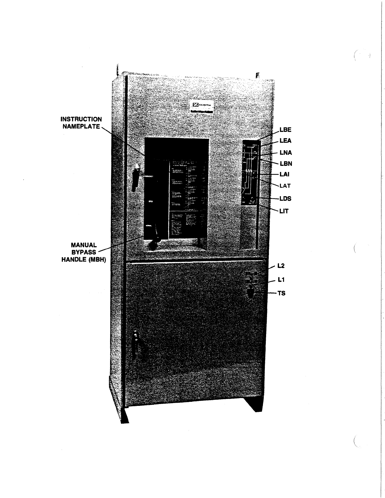
INSTRUCTION
NAMEPLATE
MANUAL
BYPASS
HANDLE (MBH)

A. CABINET ELECTRICAL PARTS
TAG DESCRIPTION PART NO.
LNA Normal Available Indicator
(G)
LEA Emergency Available Indicator (R)
LBN Bypass Normal Location Indicator
(G)
LBE Bypass Emergency Location Indicator (R)
LAT ATS Test Position Indicator
(A)
LAI ATS Isolate Position Indicator
(A)
LIT ATS Inhibit Indicator (R)
LOS ATS Disconnect Switch
"Off"
Indicator (R)
Flashing Bulb, PS-1272
COMMON PARTS BYPASS INDICATORS
Bulb Y500005
Socket PS-5046
Red Lens (R) PS-5047
Green Lens
(G)
PS-5048
Amber Lens
(A)
PS-5049
L1
L2 ATS Emergency Position Indicator
ATS Normal Position Indicator
Bulbs (Incandescent) P8-5105
Bulb Socket (Incandescent) PS-5046
Emergency Lens (Red) P8-5047
TS
Normal Lens (Green)
Test Switch
PS-5048
Operator, Momentary L-1025
Contact Block N.C. L-1029
Contact Mounting Base PS-3473
3
Rev.
11/94

~A
0B
0C
NEUT.
r--
-
~EMERG.~
BYPASS
EMERGENCY
CONTACTS
T2 LOAD T3
~
~
EN
N2
NORM.
N3
~
l.
u-
~
Ill ENGINE
START
CONNECTIONS
\
r:
AB3+4
./
AB4
t--
DETAIL 2
DETAIL
2A
DETAIL
28
DETAIL
2C
DETAIL
2D
DETAIL 2E
NYLON
ROLLER
SWITCH DETAILS
I r
AI
I
AT-I,
AT-2
\.
ZBTSH 4 POLE
4

B. BP-BYPASS AND ATS AUTOMATIC TRANSFER SWITCH POWER PANEL
TAG DESCRIPTION PART NUMBER BY AMPERAGE
Bypass 100 150 225 260 400
N1,
2,
3, N Normal }
E1,
2,
3, N Emergency LUGS P8-4418 P8-4418 P8-4418 S-1422 S-1422
T1, 2, 3, N Load
BYPASS Contact Assembly (Movable & Stationary for 3 Pole Units)
N1,2,3
Normal 46P-1104A 46P-1104B 46P-1104C 46P-1104D 46P-1104E
N (Sw. Neut. Norm.) 46P-1105A 46P-1105B 46P-1105C 46P-1105D 46P-1105E
E1,2,3
Emergency 46P-1106A 46P-1106B 46P-1106C 46P-1106D 46P-1106E
N (Sw. Neut. Emerg.) 46P-1107A 46P-1107B 46P-1107C 46P-1107D 46P-1107E
ATS Contact Assembly (Movable & Stationary for 3 Pole Units)
NL1, 2, 3 Normal 46P-1100A 46P-1100B 46P-1100C 46P-1100D 46P-1100E
N (Sw. Neut. Norm) 46P-1101A 46P-1101B 46P-1101C 46P-1101D 46P-1101E
EL1, 2, 3 Emergency 46P-1102A 46P-1102B 46P-1102C 46P-1102D 46P-1102E
N (Sw. Neut. Emerg.) 46P-1103A 46P-1103B 46P-1103C 46P-1103D 46P-1103E
Arc Grid Assy. 46P-1099
XBN,XBE
Bypass Step-Down VOLTAGE PART NO.
Transformer 25VA 120/240
K-3061
Secondary 24V 208/416 K-3063
220/440 K-3064
240/480 K-3062
380 K-3067
575 K-3065
600 K-3066
CNE Main ATS Ooerating Coils
Voltage Systems
No. Volts
Ph
Wire Coil Volts Poles PART NO.
-1
120 1 2 120 2
K-2178
-2 120/240 1 3 240 2,3 K-2189
-3 240 3 3 240 3 K-2189
-38 120/240 3 4 240 3,4 K-2189
-4 120/208 3 4 208 3,4 K-2177
-5 480 3 3 480 3 K-2176
-6 575/600 3 3 575/600 3 K-2196
-7 277/480 3 4 480 3,4 K-2176
-9 240/416 3 4 416 3,4 K-2188
-91
220/380 3 4 380 3,4 K-2188
SN
CN1
Limit Switch
SE
CE1
Limit Switch
A3 ATS Emergency Position Switch L-3002 (Detail 2)
A4 ATS Normal Position Switch
SCN/SCE CNE Limit Switches L-3079 (Detail 2a)
AA
ATS Auto Location Switch
AE1, 2 ATS Isolate/Remove Location Switch
L-3071
(Detail 2b)
PLS1,2
Position Lever Switch
AI ATS Isolate Location Switch L-3070 (Detail 2c)
AT1, 2 ATS Test Location Switch
AB3/ABE Bypass Emergency Position Switch
AB4/ABN Bypass Normal Position Switch L-5021 (Detail 2d)
NA4 Normal TRS Limit Switch
EA3 Emergency TRS Limit Switch
BTE Bypass Emergency Position Switch
BTN Bypass Normal Positiion Switch
TSE ATS Engaged Switch L-3054 (Detail 2e)
BLL
Bypass Lock Location Switch
ALL ATS Lock Location Switch
OS ATS Solenoid Disconnect Switch
Operator 2-Position Maintain L-4018
Contact Block N.C.
(1)
L-1029
Contact Block N.O. (2) L-1028
Contact Block Mounting Plate P8-3473
BPS Bypass Interlock Solenoid K-2180
TRS Transfer Release Solenoid K-2180
5 Rev. 11/94
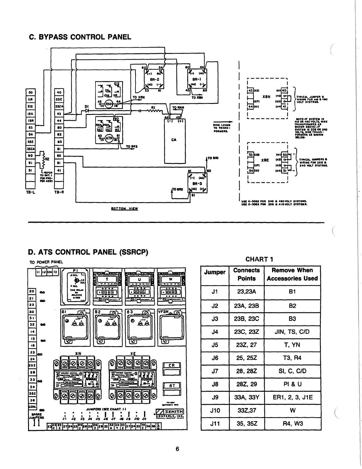
C.
BYPASS CONTROL PANEL
CA
Will
LIAOI
TO
fiiAJII•
POIIIII.L
TOIIII
BOTTOM
VIEW
TB·L
TB-R
,--------,
I XBN
,:to
I }TYPICAl.
JUII•I~
1
WUUHI
'OR
4te
a
410
I
:::
I
VOLT
IYifllll.
41
I I
~-------~
tiOTIIfP'
Sl'ITIM
IS
411
Oft
410
YOLTS.
Will
TRANSPOftlllltl
AI
SHOWN
AIOYI\
IP
lftflll
II
ZOI
ft
140
VOI..TS.WIR!TIIANS•
FOfii!MIRS
AI
SHOWN
IlL
OW·
,..-------,
I I }
XII
XBE
=~~O
-TYI'ICAL
-~•
1
~
WINING
F~
ZOI
•
:
:::
Ol
-
140
_,
IYifllll.
I I
L-----
--~
I
uu:
•·-•
•o•
140
•
•ao-.r
IYifiiiS.
1111··~
fOil
101
I 411VOLT
IYITIIII.
D. ATS CONTROL PANEL (SSRCP) CHART 1
TO
POWER
PAI\£L
JUMPERS
IIU
CHART
II
..••.
11:1.1
Jl
JZ
J:S
J4
JO , • .17
Jl
Jl
JIO
Jll
Jumper Connects
Points Remove When
Accessories Used
J1
23,23A
81
J2 23A,238 82
J3 238,
23C
83
J4
23C,
23Z
JIN,
TS,
C/0
J5 23Z,27
T,
YN
J6
25,
25Z
T3,
R4
J7 28,28Z
Sl,
C,
C/0
J8
28Z,
29
PI
& U
J9
33A,
33Y
ER1,
2,
3,
J1E
J10
33Z,37
w
J11
35,
35Z
R4,
W3
6

C.
BYPASS CONTROL PANEL (46P-1079) INCLUDES PARTS BELOW
( TAG DESCRIPTION PART NUMBER
BR1,
2.
3 Bridge Rectifier PS-5076
RNH Normal Voltage Relay Y260000
R1
Resistor RNH, 30 ohm PS-4056
R2
Resistor
LOS,
120 ohm PS-4057
01 Diode PS-4812
CA Capacitor
RNH
PS-4058
ATR Auxilary Test Relay Y260000
D. ATS CONTROL PANEL (SSRCP) STANDARD ITEMS
TAG DESCRIPTION VOLTAGE 50/60 HZ PART NO.
XN,XE
Control Transformers
(See Note
1)
120V K-3076
208V K-3070
240 or 480V
K-3071
416V K-3089
B-1,
2,
3 Phase Relays
Solid State
(See Note
1)
120V K-1185
208 or 240V K-1186
480V K-1188
VFSM Voltage Frequency Sensor 120V K-1192R
CR Control Relay 120V K-1204
AT Bypass T Relay 120V K-1204
CN1/CE1 CNE Transfer Relays (not shown) 120V K-1120
J1-J11 Jumpers PS-5067
(OPTIONAL ITEMS)
TAG DESCRIPTION VOLTAGE PART NUMBER
T Time Delay to Normal, Timer Solid State 120V
.1
Sec. to 9990 Hrs. (Adj.) K-1230
u Engine Cool Down, Timer Solid State 120V
.1
Sec. to 9990 Hrs. (Adj.) K-1230
w Time Delay Emergency, Timer Solid State 120V
.1
Sec. to 9990 Hrs. (Adj.) K-1230
PI
Time Delay Engine Start, Timer 120V (.5 to 6 sec. Adjustable)
K-1201
P2 Optional (Mounted below SSRCP) 120V (300 Sec. Adjustable)
K-1061
Notes:
1.
If -6 voltage system (575/600V) is supplied, then XN,
XE
is K-3087 and B1,2, 3 is K-1185 (120V) supplied with XB
(575;600V/120V) 3 phase transformer assembly. B1,
2,
3 mounted below SSRCP.
7
Rev. 11/94
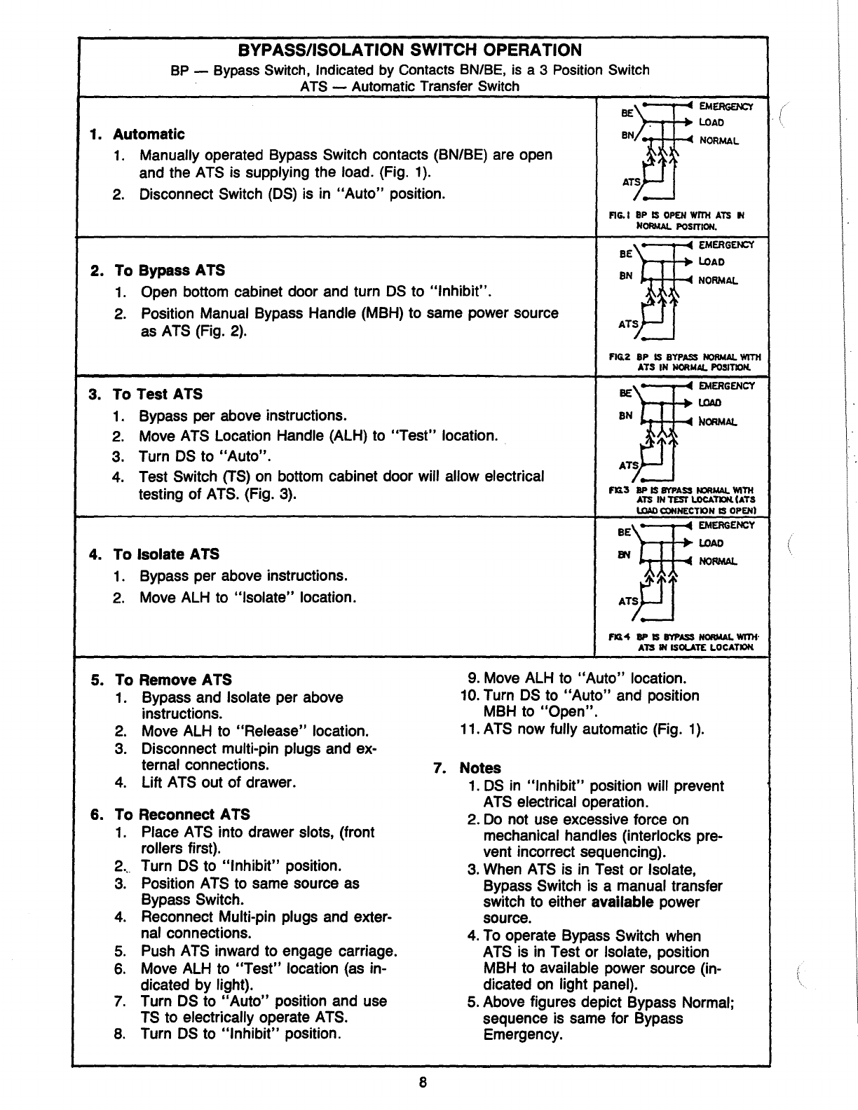
BYPASS/ISOLATION SWITCH OPERATION
BP-
Bypass
Switch,
Indicated
by
Contacts
BN/BE,
is
a 3
Position
Switch
ATS-
Automatic
Transfer
Switch
-:.
EMERGENCY
BE
,._,...p-_._+
lOAD
1. Automatic
BNJ_~~:"-
~
NORMAL
1.
Manually operated Bypass Switch contacts (BN/BE) are open
and the
ATS
is
supplying the load. (Fig.
1).
AT
2.
Disconnect Switch
(OS)
is
in
"Auto"
position. -
FIG. I
BP
IS
OPEN
WrrH
ATS
N
NORMAL
POSITION.
-:.EMERGENCY
BE
lOAD
2. To Bypass ATS
BN,/;_(
~J ~
~
NORMAL
1.
Open bottom cabinet door and turn
OS
to "Inhibit".
2.
Position Manual Bypass Handle (MBH) to same power source AT
as
ATS
(Fig.
2).
·-
FIG.2 BP
IS
BYPASS
NORMAL
WITH
ATS
IN
NORMAL.
POSITION.
3. To Test ATS
1.
Bypass per above instructions.
---.-
.....
~
EMERGENCY
BE
..,_,...p-_._+
LOAD
BN
L
-.c
~ORMAL
2.
Move
ATS
Location Handle (ALH) to
"Test"
location.
3. Turn
OS
to "Auto".
.l_
4.
Test Switch
(TS)
on
bottom cabinet door will allow electrical
Fn3
8P IS
BYPASS
NJRioiAL.
WITH
testing of
ATS.
(Fig.
3).
ATS
IN
TESI'
lOCATXlN.
CATS
l.OAO
CCNNECTION
IS
OPEN)
4. To Isolate ATS
1.
Bypass per above instructions.
2.
Move
ALH
to "Isolate" location.
5. To Remove ATS
1. Bypass and Isolate per above
instructions.
2.
Move
ALH
to "Release" location.
3.
Disconnect multi-pin plugs and ex-
ternal connections.
4.
Lift
ATS
out of drawer.
6. To Reconnect ATS
1.
Place A
TS
into drawer slots, (front
rollers first).
2..
Turn
OS
to "Inhibit" position.
3.
Position
ATS
to same source
as
Bypass Switch.
4.
Reconnect Multi-pin plugs and exter-
nal connections.
5.
Push
ATS
inward to engage carriage.
6.
Move
ALH
to
"Test"
location
(as
in-
dicated by light).
7.
Turn
OS
to
"Auto"
position and use
TS
to electrically operate
ATS.
8.
Turn
OS
to "Inhibit" position.
BE'ij:
EMERGENCY
LOAD
BN
NOIWAL.
·~
Fn4
8P
IS
IM'ASS
NORMAL
WITH·
ATS
IN
ISOLATE
LOCATIOK
9.
Move
ALH
to
"Auto"
location.
10.
Turn
OS
to
"Auto"
and position
MBH
to "Open".
11.
ATS
now fully automatic (Fig.
1).
7. Notes
1.
OS
in
"Inhibit" position will prevent
A
TS
electrical operation.
2.
Do
not use excessive force
on
mechanical handles (interlocks pre-
vent incorrect sequencing).
3.
When
ATS
is
in
Test or Isolate,
Bypass Switch
is
a manual transfer
switch to either available power
source.
4.
To
operate Bypass Switch when
ATS
is
in
Test or Isolate, position
MBH
to available power source (in-
dicated
on
light panel).
5.
Above figures depict Bypass Normal;
sequence
is
same for Bypass
Emergency.
8
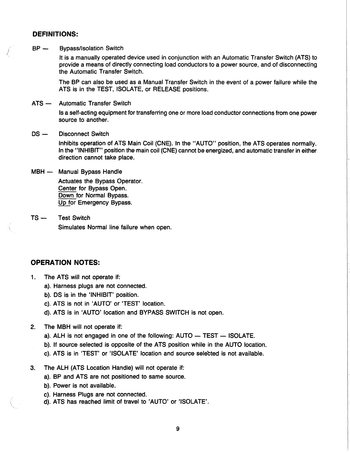
DEFINITIONS:
BP
-Bypass/Isolation Switch
) It
is
a manually operated device used
in
conjunction with
an
Automatic Transfer Switch (ATS) to
provide a means of directly connecting load conductors to a power source, and of disconnecting
the Automatic Transfer Switch.
The
BP
can also be used as a Manual Transfer Switch
in
the event of a power failure while the
ATS
is
in
the TEST, ISOLATE, or RELEASE positions.
ATS -Automatic Transfer Switch
Is
a self-acting equipment for transferring one or more load conductorconnections from one power
source to another.
DS-
Disconnect Switch
Inhibits operation of ATS Main Coil (CNE).
In
the
"AUTO"
position, the ATS operates normally.
In
the "INHIBIT" position the main coil
(CNE)
cannot be energized, and automatic transfer
in
either
direction cannot take place.
MBH -Manual Bypass Handle
Actuates the Bypass Operator.
Center for Bypass Open.
Down for Normal Bypass.
~or
Emergency Bypass.
TS-
Test Switch
Simulates Normal line failure when open.
OPERATION NOTES:
1.
The ATS will not operate if:
a).
Harness plugs are not connected.
b).
DS
is in the 'INHIBIT' position.
c).
ATS is not in 'AUTO' or 'TEST' location.
d). ATS is in 'AUTO' location and BYPASS SWITCH is not open.
2.
The MBH will not operate if:
a).
ALH
is
not engaged
in
one of the following:
AUTO-
TEST-
ISOLATE.
b).
If source selected is opposite of the ATS position while
in
the AUTO location.
c).
ATS is in 'TEST' or 'ISOLATE' location and source selected
is
not available.
3.
The ALH (ATS Location Handle) will not operate if:
a).
BP
and ATS are not positioned to same source.
b).
Power is not available.
c). Harness Plugs are not connected.
d). ATS has reached limit of travel to 'AUTO' or 'ISOLATE'.
9
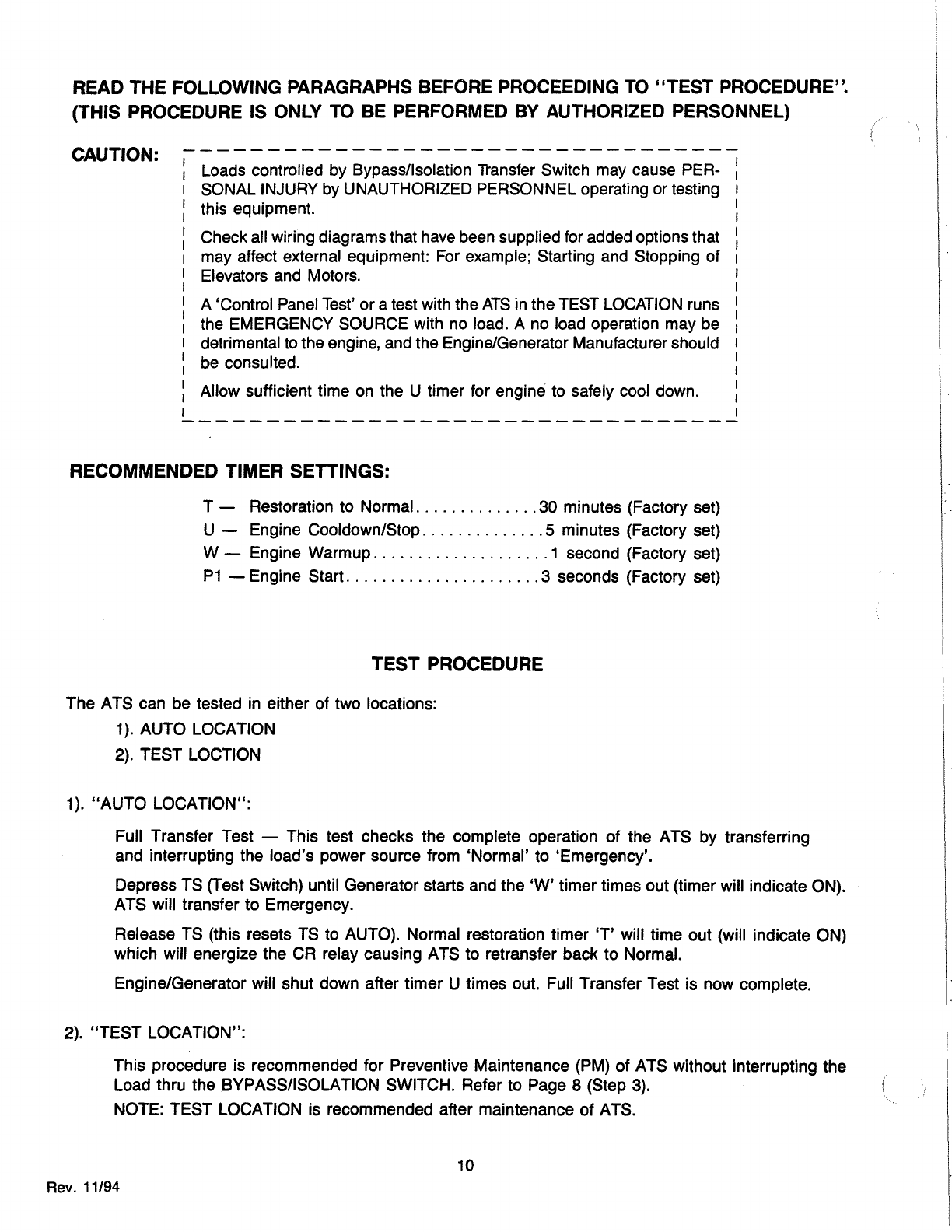
READ THE FOLLOWING PARAGRAPHS BEFORE PROCEEDING
TO
''TEST PROCEDURE''.
{THIS PROCEDURE IS ONLY
TO
BE PERFORMED
BY
AUTHORIZED PERSONNEL)
CAUTION: Loads controlled by Bypass/Isolation Transfer Switch may cause PER-
SONAL INJURY by UNAUTHORIZED PERSONNEL operating or testing
this equipment.
Checkall wiring diagrams that have been supplied for added options that
may affect external equipment: For example; Starting and Stopping of
Elevators and Motors.
A 'Control Panel Test'
or
a test with the
ATS
in the TEST LOCATION runs
the EMERGENCY SOURCE with no load. A no load operation may be
detrimental to the engine, and the Engine/Generator Manufacturer should
be consulted.
Allow sufficient time on the U timer for engine to safely cool down.
RECOMMENDED TIMER SETTINGS:
T - Restoration to Normal
..............
30 minutes (Factory set)
U - Engine Cooldown/Stop
..............
5 minutes (Factory set)
W - Engine Warmup
....................
1 second (Factory set)
P1
-Engine Start.
.....................
3 seconds (Factory set)
TEST
PROCEDURE
The ATS can be tested in either
of
two locations:
1
).
AUTO LOCATION
2). TEST LOCTION
1).
"AUTO
LOCATION":
Full Transfer Test -This test checks the complete operation
of
the ATS by transferring
and interrupting the load's power source from 'Normal' to 'Emergency'.
Depress TS (Test Switch) until Generator starts and the
'W'
timer times out (timer will indicate ON).
ATS will transfer
to
Emergency.
Release TS (this resets TS to AUTO). Normal restoration timer 'T' will time out (will indicate ON)
which will energize the CR relay causing ATS to retransfer back
to
Normal.
Engine/Generator will shut down after timer U times out. Full Transfer Test is now complete.
2).
"TEST
LOCATION":
This procedure is recommended for Preventive Maintenance (PM) of ATS without interrupting the
Load thru the BYPASS/ISOLATION SWITCH. Refer to Page 8 (Step 3).
NOTE: TEST LOCATION is recommended after maintenance
of
ATS.
10
Rev.
11/94
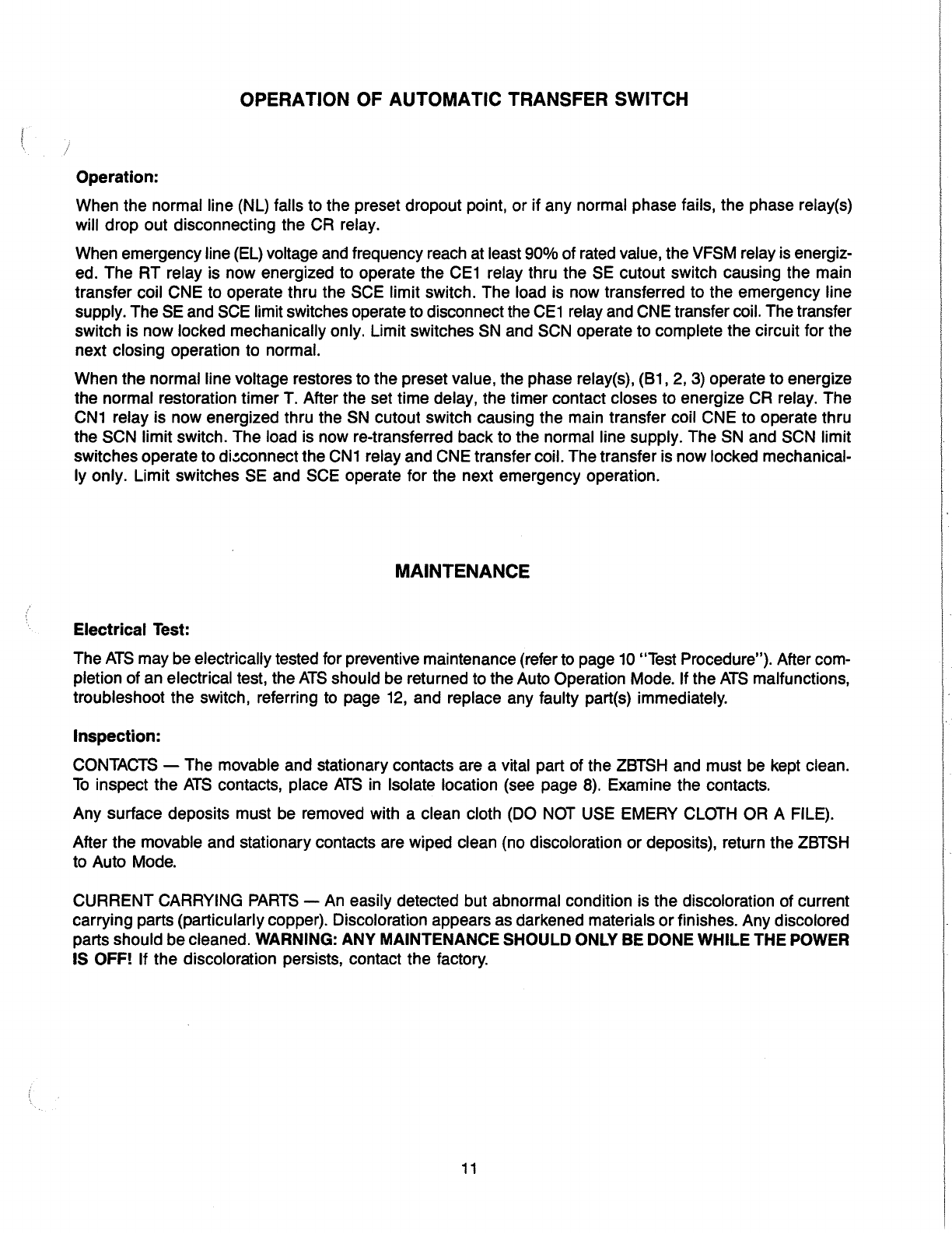
OPERATION OF AUTOMATIC TRANSFER SWITCH
Operation:
When
the
normal line (NL) falls to
the
preset
dropout
point,
or
if
any
normal phase fails,
the
phase
relay(s)
will
drop
out
disconnecting
the
CR
relay.
When emergency line (EL) voltage and frequency reach at least
90%
of
rated value, the VFSM relay is energiz-
ed.
The
RT
relay
is
now
energized to operate
the
CE1 relay thru
theSE
cutout
switch
causing
the
main
transfer
coil
CNE
to
operate
thru
the
SCE
limit
switch.
The
load is
now
transferred
to
the
emergency
line
supply.
The
SE and SCE limit switches operate to disconnectthe
CE1
relay and CNE transfer coil. Thetransfer
switch is
now
locked
mechanically
only. Limit switches SN
and
SCN operate to
complete
the
circuit
for
the
next
closing operation
to
normal.
When
the
normal
line voltage restores to
the
preset value,
the
phase
relay(s),
(81,
2, 3) operate
to
energize
the
normal
restoration
timer
T.
After
the
set
time
delay,
the
timer
contact
closes
to
energize
CR
relay.
The
CN1 relay is
now
energized thru
the
SN
cutout
switch causing
the
main
transfer
coil
CNE
to
operate
thru
the
SCN
limit
switch.
The
load is
now
re-transferred
back
to
the
normal line supply.
The
SN
and
SCN limit
switches
operate
to
di~connect
the
CN1 relay
and
CNE
transfercoil.
The
transfer
is
now
locked mechanical-
ly
only.
Limit
switches
SE
and
SCE
operate
for
the
next
emergency
operation.
MAINTENANCE
Electrical Test:
The
ATS
may
be
electrically tested for preventive maintenance (referto page 10 "Test Procedure"). After com-
pletion
of
an electrical test,
the
ATS
should
be
returned to
the
Auto Operation Mode. If
the
ATS
malfunctions,
troubleshoot
the
switch, referring to page 12,
and
replace any faulty part(s) immediately.
Inspection:
CONTACTS -The movable
and
stationary contacts are a vital
part
of
the
ZBTSH and
must
be kept clean.
To
inspect
the
ATS
contacts, place
ATS
in Isolate location (see page 8). Examine
the
contacts.
Any
surface
deposits must be removed with a clean cloth (DO NOT USE EMERY CLOTH
OR
A FILE).
After
the
movable and stationary contacts are wiped clean (no discoloration
or
deposits), return
the
ZBTSH
to Auto Mode.
CURRENT
CARRYING
PARTS-
An easily detected
but
abnormal condition is
the
discoloration
of
current
carrying
parts (particularlycopper). Discoloration appears as darkened materials
or
finishes.
Any
discolored
parts
should
be
cleaned. WARNING: ANY MAINTENANCE SHOULD ONLY BE DONE WHILE THE POWER
IS OFF! If
the
discoloration persists, contact
the
factory.
11

PROCESS
INORMAL OPERATitjG CONDITIONS I
l
URN
..
T$""
SWITCH
0
TEST
IUNTIL
TRANSFER
TO
EMERGENCY!
W
BEGINS
TIMING
RT
I N RGI
I.
ATS
TRANSFERS
TO
EMERGENCY
AND
MECHANICALLY
LOCKS.
2.
LIMIT SWITCHES SE, A3
ARE
DE-ACTIVATED
3.
Ll
IS
ENERGIZED
T BEGINS TIMING
CR
ENERGIZED
I.
ATS
TRANSFERS
TO
NORMAL
AND
MECHANICALLY
LOCKS.
2.
LIMIT SWITCHES SN,
A4
ARE
ACTUATED.
3.
L2
IS
ENERGIZED.
4,
U
BEGINS
TIMING.
TABLE
3
"TROUBLE
SHOOTING"
DECISIONS CORRECTIONS
CHECK
IF
ENGINE
START CIRCUIT IS
RECEIVING E·CONTACT
CLOSURE.
I.
CHECK
SE
LIMIT
SWITCH.
2.
CHECK
FOR
DEFECTI'VE
CCE.
1.
RELEASE
TS
SWITCH.
-,..:~--------412.
WAIT
FORT
TO
COMP'LETE
TIMING.
3.
TURN
1)$
TO.
ON.
I.
CHECK
SN
LIMIT
L-.:..=::.....----------·
2.
~mroEFECTIVE
CNI.
1.
CHECK
OS
SWITCH.
2.
CO<ECK
SOLENOID.
3.
REPEAT TEST
I.
CHECK
DEFECTIVE U.
I.
CHECK
DEFECTIVE
ENGINE
START
DEVICE.
12

New Solid State Time Delay
r--
-::-
-.
-:-."
I
',
\
---
_
..
'~-
Accessories T, U, W
Solid
State Timers
Adjustable
in
Seconds, Minutes and Hours (Plug-In Style).
To select a time unit, operate the pushbuttons of the rightmost
thumbwheel switch until the desired time unit
is
shown
in
win-
dow. The time unit can be selected by pushing the plus
(+)bot-
tom
button or the minus(-) top button. The desired time
is
specified
by operating the three thumbwheel switches
in
the middle of the
front panel.
Setting of the timer at 000 will result in
an
infinite delay. The
min. setting for OSA-A timers is 1
/,
0 of 1 second
as
shown. See
instructions.
0.1
I
0 0 1
Sec.
Close Differential (ARSM) Relay
Adjustment
The voltage points at which the relay operates are adjustable.
When the relay pulls in,
an
audible click
is
heard, and the LED
will come on.
Setting
the Relay:
If the relay should
be
set with a variable voltage supply (Variac):
1.
Turn pick-up control fully clockwise.
2.
Turn drop-out control fully counterclockwise.
3.
Set Variac pick-up voltage to desired level.
4. Very
slowly
rotate pick-up adjustment counterclockwise until
relay picks up. (LED will energize).
5.
Set Variac drop-out voltage to desired level.
6. Very
slowly
rotate drop-out adjustment clockwise until relay
drops out (LED de-energizes).
Verify settings by raising voltage until relay picks up, then lower
voltage until relay drops out, making sure that relay operates at
desired voltage levels.
LUBRICATION
The cams of the ZBTSH are lubricated with Super Lube PTFE grease, and gears with Dow Chemicals
"Molykote"
(321
R or GN paste). These lubricants provide adequate lubrication for a clean and properly main-
tained switch's lifetime. Should debris contaminate the mechanism, clean and apply additional lubricants.
Mobiltemp SHC-32
is
used
on
isolating contacts.
LUBRICATION MAINTENANCE CHART
Date Inspected Date Lubricated Lubricant Used (Cams) (Gears)
13
Notes
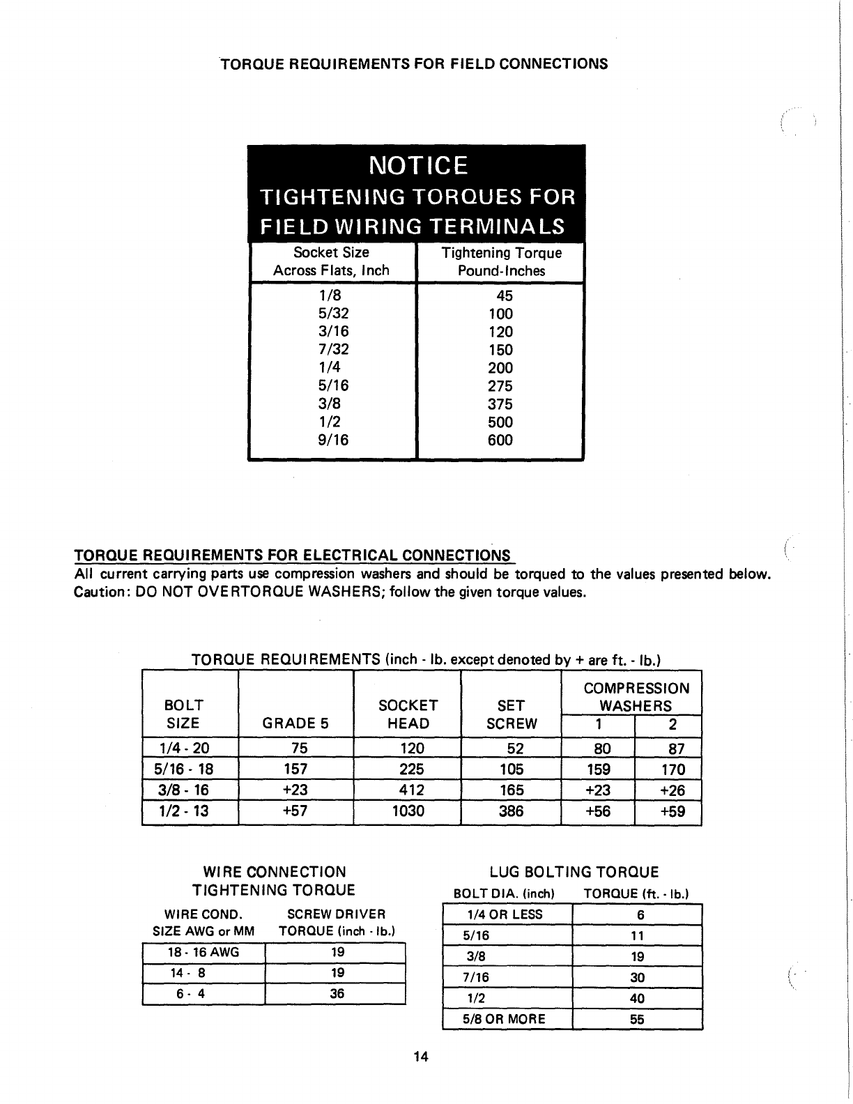
TORQUE REQUIREMENTS FOR
FIELD
CONNECTIONS
NOTICE
TIGHTENING
TORQUES
FOR
FIELD
WIRING
TERMINALS
Socket
Size
Across Flats, Inch
1/8
5/32
3/16
7/32
1/4
5/16
3/8
1/2
9/16
Tightening Torque
Pound-Inches
45
100
120
150
200
275
375
500
600
TORQUE REQUIREMENTS FOR ELECTRICAL CONNECTIONS
All
current carrying parts
use
compression
washers
and
should
be
torqued to the
values
presented below.
Caution:
DO
NOT OVE RTORQUE WASHERS;
follow
the
given
torque
values.
TORQUE REQUIREMENTS
(inch-
lb. except denoted
by+
are
ft.-
lb.)
BOLT
SIZE GRADE 5 SOCKET
HEAD SET
SCREW
COMPRESSION
WASHERS
1 2
1/4-
20 75 120 52 80 87
5/16-
18
157 225 105 159 170
3/8.
16
+23 412 165 +23 +26
1/2.
13
+57 1030 386 +56 +59
WIRE CONNECTION LUG BOLTING TORQUE
TIGHTENING TORQUE BOLT DIA. (inch) TORQUE (ft.
-lb.)
WIRE COND.
SCREW
DRIVER
SIZE
AWG
or
MM
TORQUE (inch
-lb.)
{-
.
\
1/4
OR
LESS
6
5/16
11
3/8
19
7/16 30
1/2 40
5/8
OR
MORE
55
18-16AWG
19
14-
8
19
6-
4 36
14

.\
INSIDE
IU:NOVA!l.E
f..FT
AHCLI;S
IYPASS tNEfiCENCY
HOfiNAL
AVAILAILE
IYPASS
NOlltNAL
ATI
ISOLATE
ATS
TIJT
DISCONNECT
SWITCH
INKIIIT
POSITION
..L~~~!==;;;;;;;;;;~~;;;;~~·u
"'"'"t
~roT
Ill.
CONT
..
OL
fiANEL
OF
CAIINET 00011•
LUG
CONFIGURATION
t)•POLEI
3 POLE
ZBIIH
~liD
• I c D E
"f
G
~ZZI5PI
F-1510
79
oiZll.
liO
llll
12
1114
llll
-ISPI
F-1510
79
oiZll.
liO
llll
12
1114
llll
DISCONNECT
SWITCH
NfHIIIT
POSITION
ATI I<IOIIT
,}1~~~~~~~1
...
CCIIIUOI.
PANE~
CAll
NET
DOOft.
INitD£ 01'
Lz•
A·A
---====-
CONFIOURATlON
4 POLE
ZBIIH
~
•
~ZZioU'I
79
f'oWI
_..,.,
79
f'oWI
LUG
I
oiZll.
oiZll.
Sf:£
•••
.IWU.
IITYPE
I
ENCLOSUit£
ztALL
DtN
:t
Ye
31"
Willi•
WIA£
IEHCMNG
RADIUS.
!EE
1•1
'J
11
01Ai
4
1~~:!:~D
HOLES
lWU.
IJTTPE
I
ENCLOSUA£
ZIALL
DIM
:!,
Ye
31.Willt'"
WIAE
IEHDtNO
RADIUS.
c F
D G
N
12
1114
llll
U'"
N
12
Ullo
llll
•
15 REV. 8/93
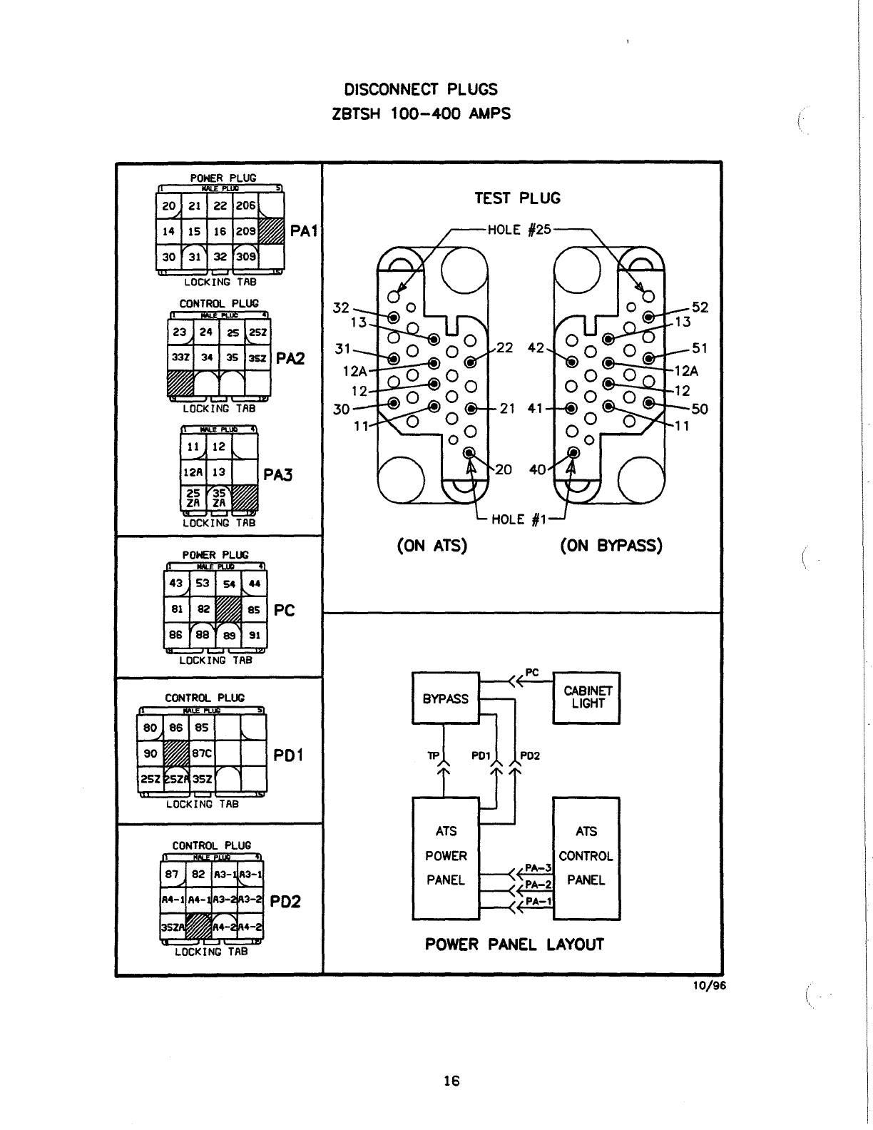
DISCONNECT
PLUGS
ZBTSH
100-400
AMPS (
PA1
LOCKING
TAB
TEST
PLUG
22
42
21
41
{ON ATS) {ON BYPASS)
PC
LOCKING
TAB
CABINET
LIGHT
ATS
ATS
CONTROL
PANEL
POWER
PANEL
LAYOUT
CONTROL
PLUG
10/96
(
16

FIELD NOTES
(
MODELNO:
--------------------------------------------------------
SERIALNO:
______________________________________________________
_
DATESHIPPED:
-----------------------------------------------------
START·UPDATE:
__________________________________________________
____
DRAWING
SUPPLIED:
-----------------------------------------------
TEST
AND
MAINTENANCE
NOTES:
DATE
TESTED
PROBLEMS
NOTES
17

2
3
4
7
•
•
10
ll
1Z
13
14
15
ENGINE
START
CIRCUIT
BYPASS CONTROL SCHEMATIC
PERMIT
CIRCUITS
25Z
ATR
25ZA
~r--=o
NORMAL
TRANSFER
PERMIT
CIRCUIT
IN
AUTO
AND
TEST
POSITIONS
35Z
ATR
35ZA
~~
EMERGENCY
TRANSFER
PERM
IT
CIRCUIT
IN
AUTO
AND
TEST
POSITIONS
LNA
-
NORMAL
AVAILABLE
LIGHT
LEA
-
EMERGENCY
AVAILABLE
LIGHT
RNH
-
NORMALLY
HELD
RELAY
01
-
DIODE
R1
-
RESISTOR.
RNH
C -
CAPACITOR.
RNH
BR-1.2.3 -
BRIDGE
RECTIFIER
AA-1
-
BTN
-
BTE
-
BPS
-
AA-2
-
ALL
-
AT-2
-
LIMIT
SWITCH.
ATS
AUTO
LOCATION
LIMIT
SWITCH.
BYPASS
TRANSFER
NORMAL
IMBH
MOVEMENT
TO
NORMALl
LIMIT
SWITCH.
BYPASS
TRANSFER
EMERG.
IMBH
MOVEMENT
TO
EMERGENCYJ
BYPASS
SOLENOID
LIMIT
SWITCH.
ATS
AUTO
LOCATION
LIMIT
SWITCH.
ATS
LOCK
LOCATION
LIMIT
SWITCH.
ATS
TEST
LOCATION
LAT
-LIGHT.
ATS
TEST
LOCATION
AI
-
LIMIT
SWITCH.
ATS
ISOLATE
LOCATION
LAI
-LIGHT.
ATS
ISOLATE
LOCATION
BLL
-
LIMIT
SWITCH.
BYPASS
LOCK
LOCATION
PLS-1-
PERMISSIVE
LIMIT
SHITCH
TSE
-
LIMIT
SWITCH.
TRANSFER
SWITCH
ENGAGED
TRS
-
SOLENOID.
TRANSFER
RELEASE
NA-4
-
LIMIT
SHITCH.
ATS
IN
NORMAL
EA-3
-
LIMIT
SWITCH•
ATS
IN
EMERGENCY
LBE
-LIGHT.
BYPASS
EMERGENCY
LBN
-LIGHT.
BYPASS
NORMAL
AB4
-
LIMIT
SWITCH.
BYPASS
NORMAL
AB3-1-
LIMIT
SHITCH.
BYPASS
EMERGENCY
PLS-2-
PERMISSIVE
LIMIT
SHITCH
ATR
-
AUTO/TEST
RELAY
AT-1
-
LIMIT
SWITCH.
ATS
TEST
LOCATION
LIT
-LIGHT.
ATS
INHIBIT
OS
-
ATS
DISCONNECT
SHITCH
R2
-
RESISTOR.
LOS
LOS
-LIGHT.
DISCONNECT
SHITCH
INHIBIT
POSITION
ALH
-
ATS
LOCATION
HANDLE
LIMIT
SWITCH
X =
ATS
ATfe
~:'fPASS
OCATION
J.too
MODE
ACTUATED
~
li
~~
01-
~~
~
l-UI
i!l!:!
AA-1.2 X
AT-1.2 X
AI
XX
ALL
X X X X
TSE
X X X
AE-1.2 X X
!NA-4
X
EA-3
X
AB4
X
AB3-1.2.3 X
BLL
X X X
PLS-1.2
ACTIVATED
HHEN
lUI
IS
OPERATED
CHART
LIM
IT
SWITCHES
oNO
~NO
~
NOT
NC
ACTUATED
r---,
ILOCATEI!
I
ON
I
~
I
IITS
I
I I
~
18
---~
..
(
10/96
Table of contents
Other Zenith Switch manuals


