Zenith Tudor 21102NZ Manual

81333NZ v1.12 09.21 Tudor Installation Instruction Page 1 of 8
Installation & Operating Instructions
Zenith Tudor
Single point open outlet (vented) under-sink water heaters
Model: 21102NZ, 21052NZ
Solo* Hero*
Accessory Tapware for Under-Sink Tudors
(sold separately)

Page 2 of 8 81333NZ v1.12 09.21 Tudor Installation Instruction
WARNING
!
Before installing, ensure that the following are available:
a) sufficient space to position the heater so there is 270 mm clear access under the heater
(over-sink models) or 270mm above (under-sink).
b) standard 10 amp 240 volt power outlet within 1500 mm of the heater
c) cold water supply with a minimum working pressure of 100 kPa and a maximum working
pressure of 350 kPa.
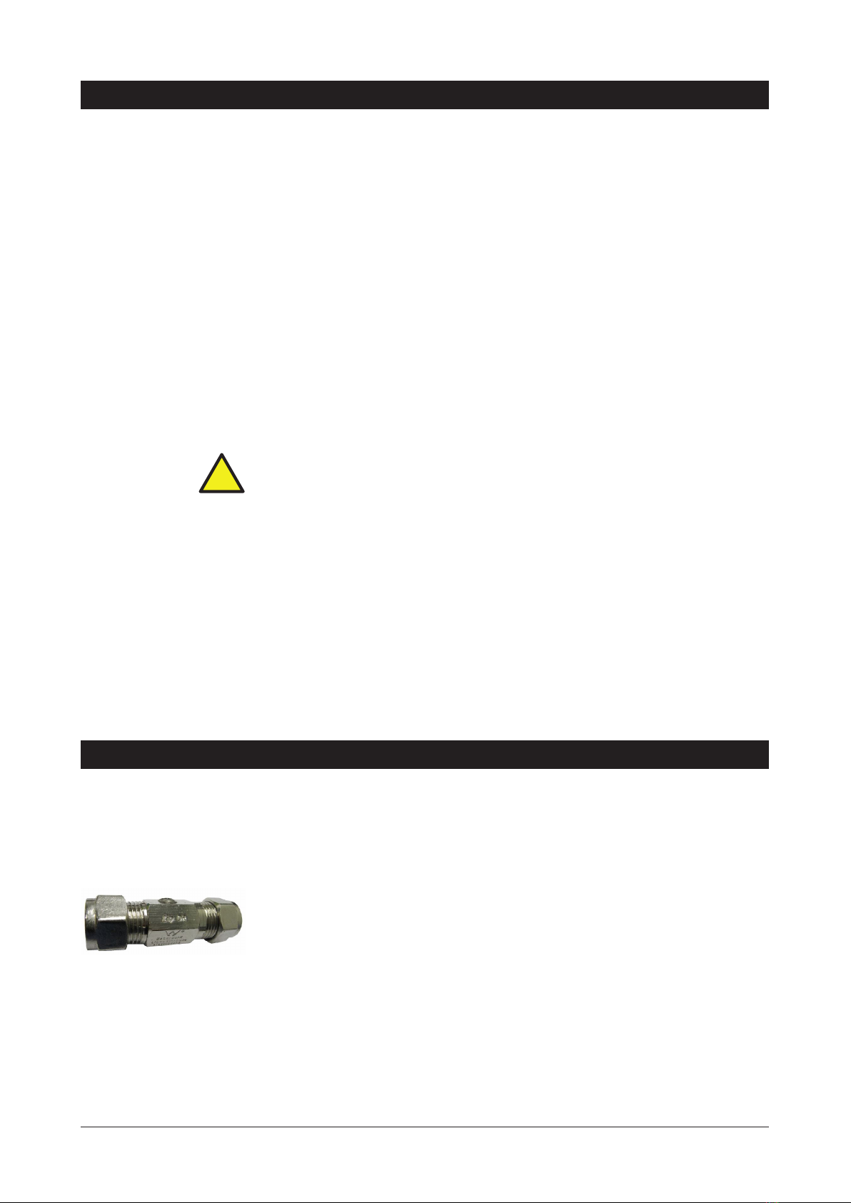
d) Isolating valve (not supplied)
If the pressure may exceed 350 kPa, a 350kPa pressure limiting valve (not supplied) must
be installed in the cold water supply line.
A double check valve (not supplied) is required to comply with the backflow requirements of
AS/NZS3500.1
Under-sink models must be installed beneath approved vented mixer taps requiring a single
mounting point on a sink, or tub. (Not recommended for basins).
Please read all installation requirements, installation procedures and precautions before
installing any Zenith Tudor water heater.
Never attempt to install the appliance without reading all of the applicable instructions.
For continued safety of this appliance it must be installed, operated and maintained in
accordance with the manufacturer’s instructions.
This appliance may deliver water at high temperature. Refer to the plumbing code of
Australia (PCA), local requirements and installation instructions to determine if additional
delivery temperature control is required.
The appliance is recommended for sinks and tubs; not recommended for basins.
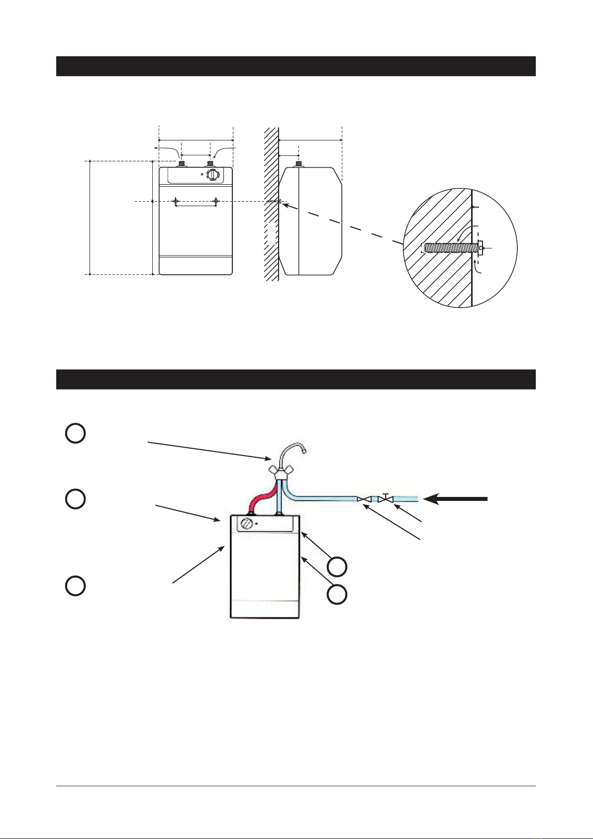
Zenith Tudor water heaters are open outlet (vented) water heaters and must not be
installed in the same way as mains pressure type water heaters.
The outlet from any Zenith Tudor water heater must be connected directly to an outlet
spout on the sink and must not be obstructed by a tap or valve or in any other way.
The water flow is controlled by a cold water tap connected before the water heater. Cold
water pushes hot water out of the tank when the cold water tap is turned ON. Any such
cold water tap should be labelled HOT.
This water heater must not be connected to more than one outlet.
All plumbing connections must be made in accordance with AS3500.
The appliance is intended only for indoor use and should never be installed outdoors or be
exposed to the elements of nature.
Over-sink and under-sink models are NOT interchangeable.
The appliance is unsuited for use by children or infirm people or those without experience;
unless they have been given supervision or instruction by a person responsible for their
safety. Children should be supervised to ensure they do not play with the heater.
If the power supply cord is damaged it must be replaced by a Zenith Service Provider or a
qualified electrician.
Do not remove the cover of the heater under any circumstances without first isolating the
heater from the power supply.
Do not turn the power ON unless the appliance is filled with water.
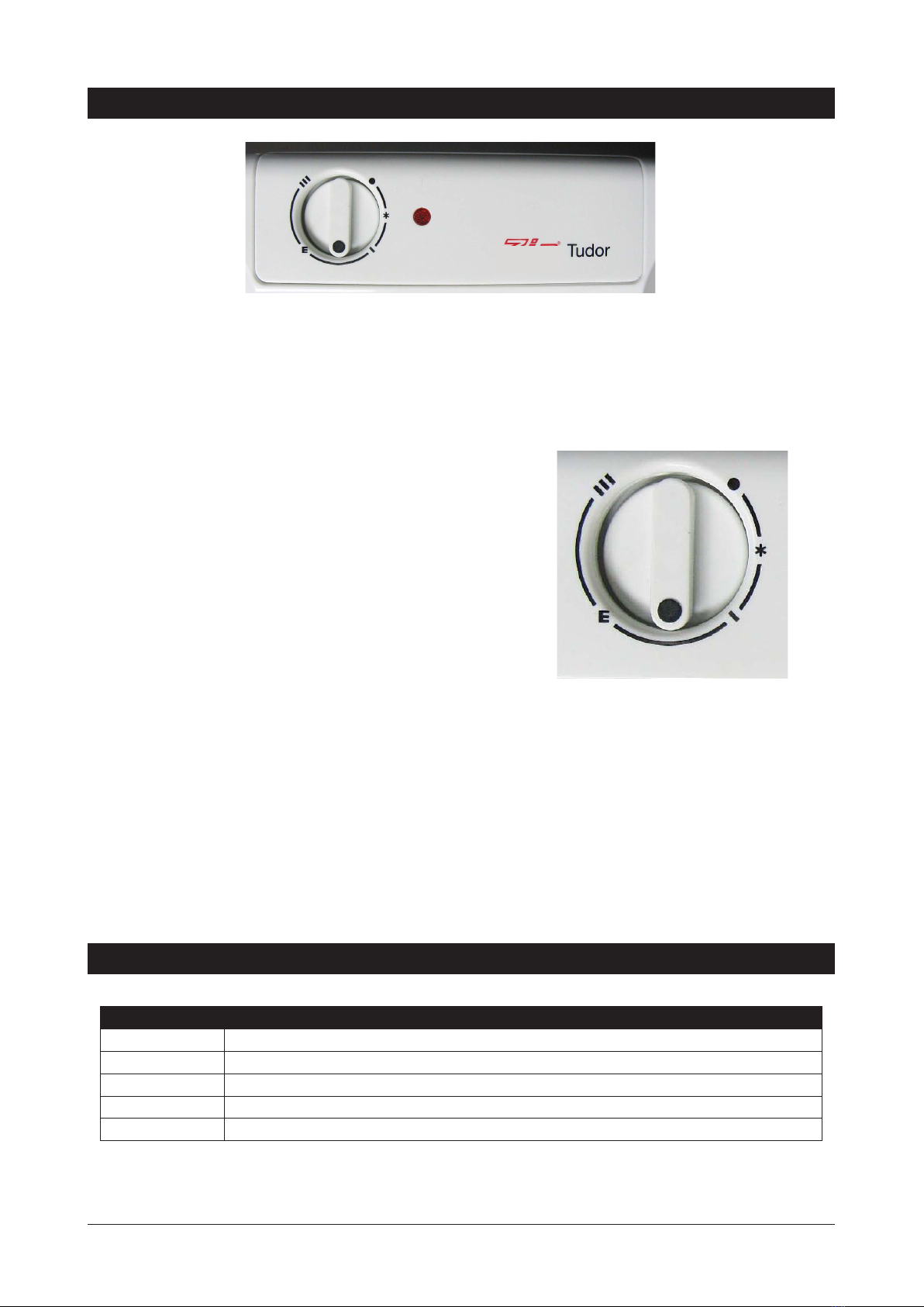
Outlet temperature should be set to no greater than 50°C without due regard to regulations
governing the storage temperature of hot water.
The appliance must not be cleaned by a water jet.
Installation requirements

81333NZ v1.12 09.21 Tudor Installation Instruction Page 3 of 8
Step One - Tapware
Note: Instructions for correct assembly and installation of Tudor tapware is included
in the tapware box. Pay close attention to these instructions.
Under-sink models must be installed with approved vented tapware. It is advisable
to fit the tap to the sink before mounting the heater to the wall beneath the sink.
1. Install the Restrictaflow valve provided, with the isolating valve (not supplied),
into the main cold water supply line. The Restrictaflow is adjustable and
must be set to deliver no more than 6Ltr/min (Max.) NOTE: Do not fit the
Restrictaflow valve to the tank (See P.5 diag)
2. Flush water supply pipes thoroughly to remove any silt or fines.
3. Fasten the tap body to the sink using the bolt & plate system provided.
4. The hose with a WHITE band on it connects to the tap hole with NO marking.
5. The hose with a RED band on it connects to the tap hole with a RED marking.
6. The hose with a BLUE band on it connects to the tap hole with a BLUE
marking.
7. Ensure that the flexible tubes are firmly attached to the base of the tap body
and in the correct sequence. Refer tapware installation sheet.
Do not dismantle the assembled tap body during installation. Mixer taps are factory
tested and sealed to provide optimum performance.
To adjust water temperature delivered by Solo and Hero mixer taps, see instructions
on page 7. Such adjustments should be made only by a qualified technician.
Step Two - Positioning
Water heaters should be installed as closely as possible or directly below the outlet
tap, with a clearance of 270 mm above the heater.
This unit must not be positioned in an area that may be cleaned by a water jet.
Step Three - Fastening
It is not necessary to remove the case of the heater during installation.
The heater must be wall mounted with two fixing screws as shown in the diagram
on page 5. Fixing screws must have the strength to support the filled heater.
The fixing screws are to protrude 4 mm from the wall as shown in the diagram on
page 5 so as to fit into keyhole slots provided on the rear of the heater.
NOTE: Failure to correctly fit the Restrictaflow valve (provided) will void the warranty
Installation
Model Weight (kg)
Empty Full
5 Litre
under-sink 3.5 8.5
10 Litre
under-sink 4.0 14.0

Page 4 of 8 81333NZ v1.12 09.21 Tudor Installation Instruction
Step Four - Connecting
The inlet and outlet water connections are located on the top of the heater.
All Zenith Tudor water connections are via 15 mm compression fittings and must
be made strictly as shown in the diagrams.
Under-sink models must be installed with approved vented tapware regulating
the incoming water supply which displaces the hot water from the heater so it
discharges through the open vented spout incorporated into the tap mounted on
the sink or tub.
The use of tapware other than approved vented tapware may result in
pressurising the heater water tank, causing damage.
Each heater is equipped with a 1600 mm power cord and plug and should be
connected to a standard 10 amp power outlet located adjacent to the heater.
When correctly installed the plug must be accessible.
NOTE: Do not turn the power ON until the heater is filled with water and air
is purged from the heater.
Step Five - Commissioning
Fill the heater tank and purge air from the heater by turning the water supply ON
and running water through the “hot” mixer tap, until water flows smoothly. Turn
the water supply OFF and turn the power supply ON. The heater will then run
through its heating cycle.
During the heating cycle, drips fall from the delivery spout or tap.
Dripping will cease when the heating cycle is completed and the stored water
temperature has reached the level set by the user.
Flow restrictor
If replacing an existing open vented water heater, an isolating valve must be
fitted to the incoming water supply. A Restrictaflow valve set at 6 litres/minute
(maximum), must be fitted to the outlet side of the isolating tap (see diagram on
page 5).
NOTE
• It is essential that the tapware is the “Open Vented” type.
• If the aerator on the end of the tap is too restrictive, it must be removed.
• The installation requirements from page 2 are also applicable.
NOTE: Failure to fit the recommended Restrictaflow valve will void the warranty
Restrictaflow valve
Retrofit instructions for open vented heaters
Installation
!

81333NZ v1.12 09.21 Tudor Installation Instruction Page 5 of 8
Cold Water Supply
Isolation Valve (not supplied)
Restrictaflow (see page 4)
Connecting (see page 4)
Commissioning - before turning
power on (see page 4)
Fasten heater to wall
(see page 3)
Position heater < 1 metre from tap
(see page 3)
Install approved vented tapware
(see page 3)
WIDTH
255 (5L)
310 (10L)
HEIGHT
390 (5L)
455 (10L)
100 70
DEPTH
215 (5L)
265 (10L)
140
COLD
IN
HOT
OUT
UNDER SINK INSTALLATION
III
III
II
EE
**
ZIPZIP
TTudor
udor
140 (5L)
180 (10L)
250 (5L)
275 (10L)
SIDE VIEWFRONT VIEW
FIXING HOLES
WALL
Wall fixing details
4 mm
gap
Anchor
Bolt
Screw
Head
Wall
Installation
Quick installation guide
1
2
3
4
5

Page 6 of 8 81333NZ v1.12 09.21 Tudor Installation Instruction
Control Panel
Water Temperature
Zenith Tudor water heaters are fully automatic, and may be left switched ON under the control of the variable
thermostat.
Nominal operating temperature can be varied from about 30°C to about 80°C.
Temperature should not be set to less than 50°C without due regard to regulations governing the storage
temperature of hot water.
Economy Setting
The economy setting “E” will maintain stored water temperature
at approximately 50°C. At the “E” setting, the temperature control
locates into a set position and a slight resistance will be felt when
rotating the temperature control beyond that setting. This measure
is to help ensure that higher temperatures are only selected
deliberately.
Frost Protection
If the heater is located where ambient air temperature could fall below 5°C when the heater is not in use, the
“anti freeze” setting on the temperature control will maintain stored water temperature over 5°C to prevent
freezing and damage to the water heater.
The same protection does not extend to connecting pipework or fittings.
Safety Cut-out
Should the heater over-heat, a manually resettable safety cut-out will automatically turn the heating element
OFF. The cut-out must be reset by a Zenith Service Provider or a licensed electrician. Users should never
reset the cut-out without qualified assistance.
ANTI-
FREEZE
ECONOMY
HIGH OFF
LOW
Operation
Spare parts
Part no Description
90836NZ Element kit (pre-August 2019)
90852NZ Gasket-New Style Element Kit Tudor 2010
90854NZ Thermostat Kit Tudor 2010
90855NZ Thermal Cut-Out Kit Tudor 2010
93865NZ Kit Zenith Mixer Tap V Arc CH Celsius Style Bright Chrome

81333NZ v1.12 09.21 Tudor Installation Instruction Page 7 of 8
Knob removed to show screw
Thermostat spade connectors
In order to help preserve our environment we ask that you dispose of
this product correctly. Please contact your local city council for collection
centre details
Service
End of life disposal
Cleaning
Never use strong, corrosive or abrasive cleaning materials. Wipe clean
the outer surfaces with a sponge or soft cloth using a mild soap and
water. Domestic dish washing liquid detergent is most suitable.
This appliance may only be serviced by a suitably qualified technician.
Disconnect from power and turn water supply OFF before attempting any kind of
service work.
Removing the case
1. Remove temperature control knob by gripping it and pulling towards you.
2. Remove the single retaining screw located beneath the temperature control
knob.
3. Remove the four case screws: two at top, two at bottom.
4. Carefully lift off the case.
To replace the case, perform the above procedure in reverse.
Replacing a thermostat
1. Remove the front cover.
2. Disconnect the two electrical terminals from the thermostat. These are
spade connectors and can be easily pulled off.
3. Remove the two screws attaching the thermostat to the plastic upright.
4. Pull the capillary out of the thermostat pocket located on the element
assembly.
5. Take the new thermostat (90421) and uncoil about half of the capillary tube.
6. Push the new capillary into the pocket ensuring that the thermostat bulb is
inserted first, before the safety cut out bulb.
7. Attach the thermostat to the plastic upright.
8. Reconnect the two electrical terminals. It does not matter which way around
the connections occur.
9. Ensure the remaining capillary coil is out of the way of any live terminals.
10. Ensure the plastic upright is located securely in the position provided.
11. Refit the cover assembly.
Tap temperature adjustment
Adjustment of a tap temperature limiter on Solo and Hero vented taps
should be made only by a Zenith Service Provider or a qualified
technician.

Page 8 of 8 81333NZ v1.12 09.21 Tudor Installation Instruction
Fault Possible cause Recommended
solution
No heat • No power
• Faulty element
• Faulty thermostat
• Faulty cutout
• Tripped overload
Check power supply
Contact Zenith
No water • No supply
• Blockage
• Faulty thermostat
Check water supply
Contact Zenith
No indicator
• Faulty LED
• Faulty connection
Contact Zenith
Troubleshooting
281737
Zenith Heaters Ltd
IRD/GST No. 95 640 729
18 Kawakawa Place, Westgate 0614 Auckland
New Zealand
zenithwater.co.nz | Ph: +(64 9) 838 8612 | Free Call 0800 558 055
Products described in this publication are manufactured under one or more
patents and further patent applications are pending.
As Zenith policy is one of continuous product improvement, changes to
specifications may be made without prior notice. Images in this booklet have
been modified and may not be true representations of the finished goods.
© 2020 Zenith Heaters Ltd.
This manual suits for next models
1
Table of contents
Other Zenith Water Heater manuals