Zenith C-9000 Maintenance manual

Zenith®Pumps
Installation,
Care and
Maintenance
Zenith
Corrosive Duty
Gear Pumps
C-9000
Gear Pumps

2
Note: Thoroughly read and understand this entire manual
before installation and operation of the pump.
Zenith®
Benefits
In 1926, Zenith Pumps was approached
by the synthetic fiber industry to design
a pump that would provide precise,
pulseless and repeatable flow while
ensuring ultimate product quality. The
options then were the same as those in
the chemical process industry today—
diaphragm, lobe, coarse gear, piston,
plunger and screw pumps. Each has
problems with pulsation, flow inaccura-
cies, multiple seal areas and slip, which
require constant calibration, high main-
tenance and extended downtimes.
Zenith Pumps met the challenge
and designed a rotary external gear
pump of unique precision and simplicity.
Manufacturing techniques were devel-
oped to hold tolerances to ±.00005",
minimizing internal clearances and
assuring accurate and precise metering.
The pump’s simplistic design of only
three moving parts – two metering gears
and a drive shaft – provided long life
and reduced maintenance.
For years, engineers have relied on
Zenith to provide precision fluid han-
dling solutions for their most difficult
pumping applications. Zenith gear
pumps can be found wherever precise,
pulseless, and repeatable metering of
fluids is required.
High Accuracy — Stable, repeatable
flows are assured even under varying
conditions of temperature, viscosity and
pressure.
Precision Construction — Ground and
lapped components allow for operating
clearances to .00015" and provide high
volumetric efficiency.
Minimum Pulsation — Unique design
offers virtually pulseless flow without
valves or flexible elements to hinder
performance.
Active Flowmeter Concept —
Unparalleled mechanical precision,
combined with the closed loop set point
accuracy, ensures an exact volume
per revolution without expensive flow
meters.
Low Cost of Ownership — With only
three moving parts and 316 stainless
steel compatible construction, the pump
provides excellent corrosion resistance
for most chemical processes.
Experience — Zenith has over 74 years
of application experience with engineers
available 24 hours a day to support your
precision fluid metering needs.
Specifications Capacities (cc/rev):
0.3, 0.6, 1.2, 2.4, 4.5, 9.0
Recommended Speed:
up to 1000 rpm
Flow Range:
up to 9,000 cc/Minute
(2.4 GPM)
Inlet Pressure:
300 psi (20 Bar) Maximum
Outlet Pressure:
1000 psi (70 Bar) Maximum
Differential Pressure:
20 to 1000 psi. (viscosity dependent)
Temperature:
-40° F (- 40° C) Minimum
350° F (175° C) Maximum
Seals:
Single Mechanical, Double Lip, or
Magnetic
Rotation:
Clockwise (CW) facing drive shaft
Port Connections:
Metric thread or SAE 61 Standard
Optional Port Adapters:
M12 X 1/4" NPT. . . . . . . . . 0.3 – 2.4 cc/rev
1/2" SAE X 1/2" NPT. . . . . 4.5 – 9.0 cc/rev
Optional Band heaters:
150 Watt, 115 VAC. . . . . . 0.3 – 2.4 cc/rev
325 Watt, 115 VAC. . . . . . 4.5 – 9.0 cc/rev

3
Quick Start:
Introduction:
1. If you are familiar with installation of Zenith pumps please read over the list of
Do’s and Don’ts on page 15.
2. Special care must be taken: The C-9000 pumps are easily damaged in handling
due to the soft metal used in their construction.
3. It is strongly recommended that you thoroughly read through this entire manual
before you begin installation or any servicing of the C-9000 pumps.
This manual was specifically written
for the 0.3, 0.6, 1.2, 2.4, 4.5, and 9.0
cc/rev C-9000 pumps. It will guide you
through the process of maintaining and
caring for your pump.
C-9000 series pumps are similar in
concept to other Zenith pumps, however
several key physical aspects differ in ways
which will affect the care and maintenance
of the product. The following literature will
discuss, in detail, how to care and main-
tain a well running and efficient pump in
order to maximize the productivity and
effectiveness of your Zenith product.
Below are a few key points which
must be considered in order to prevent
damage to the product during handling,
installation and cleaning.
Most importantly
1. Use only brass or plastic tools to pry
on the C-9000 pump components;
2. If you must hammer on the pump, use
a clean plastic hammer (no imbedded
metal chips, etc.) and tap lightly;
3. Do not perform maintenance on the
silicon carbide sleeve bearings.
4. Use force, not impact, to move
stubborn parts.
Again, the C-9000 pumps are not as
hard as the tools found in most mainte-
nance areas, and can be damaged by
common steel tools. This is one feature of
the pump that must be taken into consid-
eration in the installation, disassembly
and assembly procedures.
The specially designed bearings
require an interference fit installed at the
Zenith plant and should not be removed
by the customer. These sleeve bearings
are extremely brittle and fragile, and can
be easily broken resulting in multiple part
damage and high replacement cost. See
Figure 1. The sleeve bearings should not
need to be replaced during routine main-
tenance.
If you follow the above suggestions
and the Do’s and Don’ts list (page 15),
you will be able to maintain a C-9000
pump with little chance of damage.
Figure 1

4
Start-Up
Installation: The following is a general installation
procedure for Zenith C-9000 Series
metering pumps. The procedure may
vary slightly depending on the pump
model purchased. For special applica-
tions, considerations, or technical assis-
tance, please contact your representative
or our Applications Engineering Group.
Things to remember
1. The pump should be carefully
unpacked and inspected. If any items
are missing or damaged, the freight
carrier and Zenith should be notified
immediately.
2. Take Care! - The pump is a precision
instrument. Dropping the pump on
a hard surface or striking the pump
with a hard object can cause serious
damage to the components.
3. Treat the pump as a precision
gauging instrument.
4. Always flush the piping system before
connecting the pump.
5. Filters should be installed upstream of
the pump. For C-9000 pumps, the
fluid should be filtered to five (5)
microns, absolute.
6. Zenith C-9000 pumps must never be run
without a fluid. C-9000 pumps contain
no lubricant when shipped from the
factory. Prior to start-up, the pump
must be wetted by priming the pump
with the process fluid, or by pouring
fluid into the inlet port and rotating the
drive shaft until fluid appears at the
discharge port. The product to be
pumped can be used as this fluid,
assuming it will not evaporate prior to
the pump actually being started.
Remove seal housing plug and fill
with compatable fluid. This will ensure
that the shaft seal is lubricated.
7. Turn pumps by hand before start-up
to ensure free rotation before starting
the drive.
8. For applications above ambient tem-
peratures, if using heaters, heat the
pump slowly and evenly (including the
seal arrangement) prior to introducing
hot fluid into the pump. This prevents
thermal shock and material distortion.
9. Make sure that process fluid is in the
pump before starting. Apply positive
pressure to the pump inlet when
metering high-viscosity fluids to
prevent cavitation.
10. Install a pressure regulating valve
downstream of the pump, if necessary,
to ensure there is at least 20 psig
differential pressure at all times.
Installing the pump
Install the selected fittings into the
inlet and discharge ports, taking care not
to over tighten the fittings. Mount the
pump to the base plate using the two
mounting screw holes on the bottom of
the front plate. Align the pump shaft to
the shaft on the gear reducer using a
shaft alignment gauge, laser alignment
mechanism, or by carefully using a
straight edge to control the coupling
alignment. Jaw-type couplings are not
recommended as shaft misalignment
must be controlled to within .008 inch
parallel and to within 1° angular. For
Zenith-supplied systems (pump, reducer,
baseplate, coupling, etc.), the shaft mis-
alignment should be controlled to within
.035 inch parallel and to within 1° angular,
but these values may need to be adjusted
depending on the particular coupling
chosen for your application. When
installing the coupling end member onto
the pump shaft, do not use excessive
force. This connection should be a slip fit.
If not, increase the inside diameter of the
coupling accordingly.
If your pump was designed to use an
outer drive gear, you must grease the
outer drive gear and carefully mesh it
with the drive pinion gear. A backlash of
.005” is recommended.
1. Allow enough time for all components
of the system to reach process tem-
perature before starting the pump.
Apply inlet pressure to the pump,
allowing time to ensure that the
process fluid has entered the pump
to prevent the bearing areas from
running dry.
2. Before starting, remove all flow
restrictions downstream of the pump
to provide initial operation with the
slightest amounts of back pressure.
3. Set the acceleration rate for the pump to
be 0.3 seconds/rpm or more. Prior to
start-up, adjust the acceleration rate
of the controller to ensure initial slow
speed operation. This corresponds to
600 seconds to reach 2000 rpm, or .3
seconds/rpm.

5
Start-Up (cont.) 4. Start the pump and accelerate to 30 rpm
or to the lowest set point of speed for the
application, whichever is less. Watch the
point of discharge for evidence of
fluid. If no discharge is seen after 10
revolutions of the shaft shut down the
pump and check for obstructions in
the system and proper pump rotation.
This is assuming a connection can be
broken within a few inches of the
pump outlet port, where the flow would
be evident within several seconds. If
the distance between the pump outlet
and the point of discharge inspection
were long, more time would be needed
before flow is confirmed. This is more
risky, and damage to the pump might
result if it is run dry for more than 30
seconds.
Note: The pump will discharge a cloud of
bubbles when it is started, but this
will subside when the air is purged
from the pump. This is a normal
part of pump startup.
5. When smooth flow is seen at the dis-
charge the pump and system can be
gradually brought up to normal oper-
ating speeds and pressure. Listen for
unusual sounds when first starting the
pump and turn the pump off immedi-
ately if any are heard. Investigate for
causes of distress.
6. If, at any time during operation, the
pump does not appear to be running
smoothly, stop the pump immediately
to avoid serious internal damage.
Flushing of the product piping
Take care when flushing the pump or
downstream process equipment using
the Zenith precision metering pump as
the flushing pump. The pump must be
able to withstand the solvent or flushing
agent as well as the product, and the
operating speed and pressure during
flushing must still fall within the applicable
range for the C-9000 product.
If it is necessary to flush the system,
the following suggestions are recom-
mended to prevent pump damage:
1. Minimize the differential pressure
across the pump ports to less than
100 psi, but not less than 20 psi.
2. Reduce the pump speed to an
acceptable level, approximately
50-100 rpm.
3. Flush the pump for the shortest
allowable time, yielding effective
cleansing of the system, and no
longer than necessary.
4. Another alternative is to use a bypass
around the pump, as illustrated in
Figure 2, this will allow for high velocity
flushing of the downstream system
while minimizing risk to the metering
pump. During the flush cycle, run the
pump slowly. The fluid will pass
through and around the pump. This
will allow the system to be flushed
quickly and effectively.
5. If it is necessary to also flush the seal
housing, and the discharge pressure
is higher than the suction pressure
(during flushing cycle), connect the
seal housing drain to the suction line
(dotted line on Figure 2).
Pump
Valve Bypass
Figure 2
Care During
Operation
How does the pump work?
Fluid enters the pump through the
inlet port located in the front plate and
fills the gear pocket. As the gears rotate,
a precise amount of fluid is trapped
between the side walls of the gear
pockets and gear teeth.
The metered fluid is transported by the
rotation of the gears to the discharge side
of the pump where the gear teeth come
into mesh. This action forces the fluid out of
the gear teeth and through the outlet port
located in the front plate. The pressure
developed is determined by the pump
size, the gear clearances, pump speed,
fluid viscosity and impedance to flow.
How fast can I run the pump?
Pump speed is limited by practical
considerations. If a high viscosity fluid is
being metered and pump speed is
increased beyond a certain point, the
fluid may not be able to fill the gear teeth
spaces, and the pump will not obtain
enough fluid to maintain normal volumetric

6
Care During
Operation
(cont.)
efficiency. Lack of sufficient fluid is called
starvation or cavitation. This can be
remedied by increasing the inlet pressure
or reducing pump speed.
Pumping thin fluids requires a different
approach. Since the pump depends upon
the metered fluid for lubrication of internal
bearing surfaces, speeds are normally
limited. These bearing surfaces include the
bearing areas in the front and rear plates.
Operating a Zenith pump above indicated
speeds will accelerate wear and may cause
seizure, especially if the fluid is a poor
lubricant at operating temperatures. It is not
recommended to pump abrasive fluids with
C-9000 pump models. In certain applica-
tions, it is recommended to use a pump of
larger capacity operated at a lower
speed. Contact your representative or our
Applications Engineering Department for
assistance with this special case.
Inlet Pressure Requirement
Once the pump is installed the inlet
port pressure must be found and adjusted
to an acceptable level. It is highly recom-
mended that the inlet port pressure be at
least one atmosphere. It is, however,
acceptable to have 0.5 atmosphere or
even vacuum at the inlet assuming the
port is flooded. It is also imperative that
the pumping losses from the tank to the
inlet port be considered in this procedure.
A high viscosity fluid requires a high inlet
pressure; a low viscosity fluid requires a
low inlet pressure. Once the pump has
started cavitation will occur if the inlet
pressure is not high enough. Cavitation
may damage the pump so if it occurs
stop the pump immediately. Keep in mind
that once the inlet is flooded and the
pump is started there will be a head loss
across the inlet port of the pump. Table 1
on the next page has been included for
reference.
De-rating the Pump Performance
Pump displacement depends on four
basic variables: fluid viscosity, gear clear-
ances, differential pressure and pump
speed. The pump performance is
de-rated, or reduced from the ideal value,
due to slip of the product fluid around the
gears from the discharge side back to
the intake side.
The less viscous the fluid, the more
likely it is to flow through a given orifice.
For de-rating the pump, this orifice is the
gear clearance. Differential pressure
forces the fluid through this clearance at
a steady rate, regardless of the pump
speed. Thus, the slip flow is constant for
a given amount of time. The actual delivery
of fluid is the measured delivery minus the
slip. This means the pump displacement
is still linear. If we increase the pump
speed we increase the measured deliv-
ery, while the slip remains constant. Slip
flow is repeatable and predictable, and
pump operation can be adjusted to
compensate for this flow.
Graph 1 on the next page has been
included for reference.
Operating at elevated temperatures
Zenith C-9000 Series pumps are
designed for operating temperatures less
than 176°C. When operating at tempera-
tures above ambient, heaters should be
used, and pumps should be heated slowly
and uniformly to avoid distortion and
internal component interference.
Magnetic Coupling Pumps
In normal operation, the magnetic
poles of the outer drive magnet remain
aligned with the magnetic poles of the
inner pump magnet. The motion of the
motor is smoothly transferred to the pump
shaft. If the torque load on the pump
exceeds the magnetic coupling strength,
then the outer magnets will rotate past
the inner magnets and the magnetic poles
will misalign. The outer magnet will
increase to a no-load motor speed while
the inner magnet remains relatively motion-
less. Excessive noise and vibration can
be observed as the poles of a decoupled
magnet move past one another.
The pump should be stopped
immediately if the magnets decouple.
Continued operation of the motor with the
magnets decoupled will reduce the future
strength of the coupling. The magnets will
not properly realign until the motor has
been stopped. Before restarting the
motor, one should determine the cause of
the decoupling and remedy the problem.
Decoupling does not necessarily indicate
a pump failure. It indicates that an instan-
taneous torque requirement of the pump
has exceeded the strength of the mag-
netic coupling supplied with the system.
Without disassembly of the pump it
can be difficult to determine whether the
magnetic coupling or the pump internals
are operating incorrectly. The following is
a list of examples that could result in
magnet decoupling:
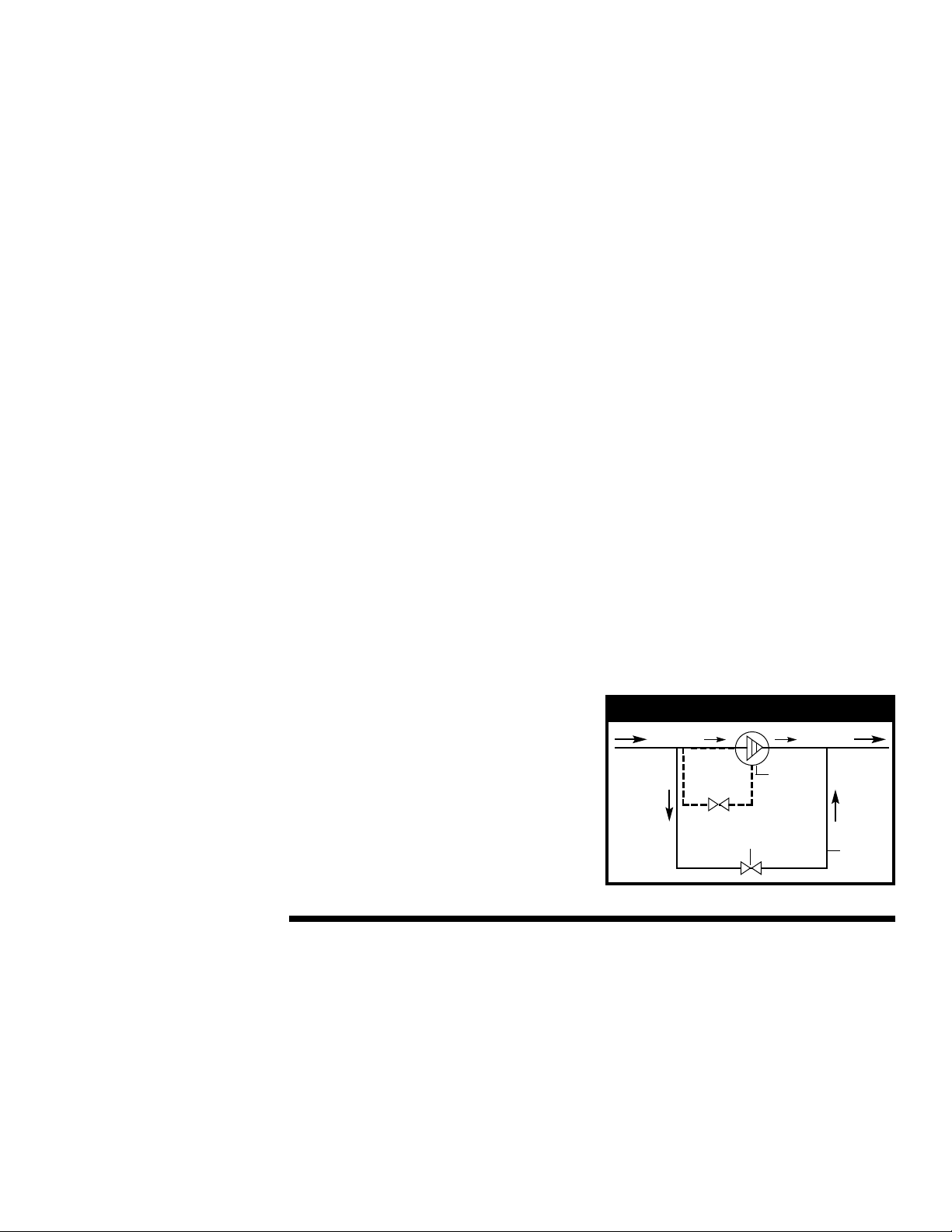
• Blockage or restriction in the
discharge side of the system

7
• Discharge pressure in excess of
nominal conditions
• Too rapid acceleration or deceleration
of the drive system
• An increase in fluid viscosity
• Foreign particles impinging upon
pump internal components
• Increased friction due to a poorly
lubricating process fluid
The decoupling characteristic of mag-
nets can be a safety feature, preventing
inadvertent pump/motor overloads.
Magnets should be chosen so that their
decoupling torque is greater than the
pump input torque. This should include
any transient, starting, and stopping con-
ditions in addition to steady state values.
The decoupling torque can vary with
different fluids, temperatures, operating
pressures, and magnet sizes. Accurate
sizing of magnets for a specific
application requires precise knowledge of
several operating conditions. Check with
your Zenith representative to see which
9000-MD system is appropriate.
General Magnetic Coupling
Precautions
Both the inner and outer magnetic
rotors are very powerful. Handle them with
caution.
Danger! Persons with cardiac pacemakers
should stay at least 8 feet from the
magnetic product at all times.
Do not position hands or fingers so
that they may become trapped between
the two magnetic rotors, or between one
magnet and a metal object.
Do not position the magnets near one
another unless assembling the pump to the
system. Both rotors should be fastened to
their respective shafts before bringing
them into proximity.
Do not place the magnets near any
electronic equipment or media that is
sensitive to magnetic fields ( computers,
diskettes, credit cards, etc.)
When storing and assembling the
magnetic coupling, make sure that no
small metallic fasteners, pieces or other
foreign objects adhere to the rotors or
barrier cap.
If the magnets de-couple, stop the
drive system for the pump immediately.
Determine the cause of the excessive
torque requirement and remedy the
problem prior to re-starting the system.
Care During
Operation
(cont.)
Key:
∆P = Pressure (psi)
µ= Viscosity (cp)
N = Speed (rpm)
0.00 0.001 0.01 0.1 1 10 100
0.10
0.20
0.30
0.40
0.50
0.60
0.70
0.80
0.90
1.00
∆P/(µ•N)
Derating Factor
0.3 cc/rev
4.5 cc/rev
9.0 cc/rev
0.6 cc/rev
1.2 cc/rev
2.4 cc/rev
C-9000 Pump Performance
Graph 1
Inlet Pressure Loss (psi) = Viscosity(cps) •Displacement(cc/rev) •Shaft Speed(rpm) •[(Specific Gravity •W1)+W2]
Note: This sizing procedure should be used as a
guideline for estimating pump type, pump size
and system requirements. Please consult Zenith to
confirm pump and system selection prior to placing
a purchase order.
Flowrate = pump capacity (cc/rev) x rpm x performance factor
WARNING
cc/rev W1 W2
0.3 4.29E-06 2.32E-06
0.6 1.93E-06 2.47E-06
1.2 1.21E-06 2.77E-06
2.4 9.34E-07 3.38E-06
4.5 3.00E-07 3.46E-07
9.0 2.24E-07 4.19E-07
Table 1

8
Cleaning,
Inspection
and Repair
REMEMBER: Zenith metering pumps
are made for exacting duty. In order to
develop high pressure and minimize slip
flow, the clearance between the metering
gears and the housing must be as small
as possible, yet large enough to allow
adequate lubrication. All parts are
machined to extreme accuracy. Critical
dimensions are held between one and
two ten-thousandths of an inch (2 to 5µ).
Consistent performance is dependent
upon proper handling.
Please handle the pumps with extreme
care and set aside a separate clean area
for pump maintenance and repair.
It is recommended that pump users
institute a program for dimensional
inspection of critical parts in order to
keep maintenance and operating costs to
a minimum. By noting the performance of
a pump immediately before removing it
from service and correlating the perfor-
mance to measured component wear,
the maximum wear limits for the pump’s
critical components can be established.
Additionally, the service life of the pump
can be predicted and downtime can be
scheduled accordingly.
If necessary, any Zenith precision
metering pump requiring maintenance
can be returned to the factory for complete
repair and overhaul. For a large number
of pumps, Zenith offers a contract repair
service, which helps to reduce repair
costs and delivery time. Zenith Pumps
also offers pump maintenance seminars.
For more information concerning Zenith
pump repair services, please contact our
Customer Service Department.
C-9000 Series
Disassembly
Instructions below assume the pump
has been removed from the system, for
example magnetically driven pumps with
adapter plates have been disengaged
from the housings.
Note: As parts are disassembled, place them
carefully on a clean surface such as a soft
cloth. See Figure 3. Do not allow them to
touch each other. Pay close attention to the
order in which parts are removed. This will
aid in the reassembly of the pump. The
numbers in parentheses refer to the part
numbers on the bill of materials.
Caution: Please review the precautions
listed on Page 7 for Magnetically
Coupled Pumps.
1. If the pump came with an outer drive
gear, remove it from the drive shaft
before starting disassembly.
2. Remove the square key (17) from
the shaft end.
3. If applicable, remove the socket head
screws (18) from the seal housing (11).
See Figure 4.
4. Lift off the seal housing (11). Take care
to also remove the o-ring (33) which
seals the housing to the front plate. The
ring may be attached to the front plate.
5. Remove the seal (51) [item 13 on
4.5 & 9 cc/rev pumps] from the seal
housing (11).
a) Mechanical Face Seal Pumps; The
ceramic seat of the mechanical face
seal may be removed from the seal
housing by pushing it out with finger
pressure. If it is stuck, use two small
Allen keys or other small pins to press
the seat from the housing using the two
access holes in the housing face. Set
screws will have to be loosened to allow
removal of the mechanical seal (13)
from the drive shaft. Some materials of
the seal (face) are brittle in nature, use
extreme caution so as not to damage
the seal or its components. Remove the
retaining ring (16) from drive shaft with
a brass or plastic tool.
b) Double Lip Seal Pumps; Press the lip
seal (51) [item 13 on 4.5 & 9 cc/rev
pumps] from the housing using finger
pressure, or by pressing on the seal
using a plastic tool.
Figure 3
Figure 4

9
C-9000 Series
Disassembly
(cont.)
C) Magnetically Coupled Pumps
If applicable, remove the screws that
secure the barrier cap to the adapter
plate. Remove the barrier cap and its
O-Ring. NOTE: There could be process
fluid contained in the barrier cap. Loosen
setscrew at the bottom of the inner rotor
with appropriate Allen wrench. NOTE:
Beware of strong magnetic forces.
Slide the inner rotor off the shaft.
Remove the square key from the
pump shaft. Remove the four socket
head screws/washers securing the
adapter plate to the pump body. Lift
the adapter plate off the pump body
and retrieve the O-Ring.
6. Now set the pump in a vice that has
soft, protective jaws made of brass,
aluminum, plastic or any material softer
that 316ss. Orient the pump with the
drive shaft pointed down. Allow the
vice to grip the pump on the port sides
of the front plate.
7. Loosen and remove the socket head
screws (19) [and 15 if applicable], from
the back of the rear plate (7).
8. Remove the rear plate (7). Always use
the pry slots to prevent scratching the
precision lapped surfaces. Use brass
or plastic tools to pry, if necessary. Take
care not to press on the gears or the
edges of the gear pocket.
Caution: Do not allow the gears to be lifted
out of the gear plate. They may drop,
causing damage to the gear teeth. See
Figure 5.
9. Remove the drive shaft (2) and the
driving gear (5). The round key (4) will
fall from between the gear and the
drive shaft.
10. Remove the retaining ring (16) from the
drive shaft with a brass or plastic tool.
11. Remove the arbor (9) and the driven
gear (5) from the gear plate (3). Note:
The driven and driving gears are
identical in most models.See Figure 6.
12. Remove both retaining rings (16) from
the arbor (9) using brass or plastic
tools. Remove the driven gear (5)
from the arbor (9). See Figure 7.
13. Remove the round key (4) from
the arbor (9).
14. Remove the gear plate (3). Always
use the pry slots to prevent scratching
the plates!
Caution: The slip-fit dowels (10) may
come off with the gear plate.
15. Remove both slip-fit dowels (10) by
turning and pulling simultaneously.
It is acceptable to lightly press the
dowels out using an arbor press.
Use a brass or plastic pin to press
against the dowel.
16. Remove the o-rings (34) from the front
and rear plates with a brass or plastic
tool.
17. Do not attempt to remove the special
bearings located in the front and rear
plates. See Figure 8.
Figure 5
Figure 6
Figure 7
Figure 8

10
0.3 - 2.4 cc/rev C-9000
18 SHCS M6x1
11 Lip Seal Housing
23 Sleeve Bearing
24 Sleeve Bearing
45 Spacer Bushing
45 Spacer Bushing
20 Rear Plate
3 Gear Plate
21 Front Plate
10 Hollow Dowel
9 Arbor
Round Key 4
Drive Shaft 2
Driving Gear 5
Rear Plate Assembly 7
SHCS M10x1 19
SHCS M6x1 15
Front Plate Assembly 8
O-Ring 33
O-Ring 34
Tandem Lip Seal 13
Dryseal
Type Plug 42
Interpret per
ASME-Y14.5M 1994
Square Key 17
18 SHCS M4x 0.7
11 Seal Housing
23 Sleeve Bearing
16 Retaining Ring
24 Sleeve Bearing
35 Dryseal Type Plug
2 Drive Shaft
20 Rear Plate
3 Gear Plate
21 Front Plate
10 Hollow Dowel
9 Arbor
Round Key 4
Driving Gear 5
Rear Plate Assembly 7
SHCS M6x1 19
Front Plate Assembly 8
O-Ring 33
O-Ring 34
Tandem Lip Seal 51
Interpret per
ASME-Y14.5M 1994
Square Key 17
4.5 & 9.0 cc/rev C-9000

11
Inspection
and Part
Preparation
After the parts have been cleaned,
they should be inspected for nicks, burrs
and stubborn residue. The gears and the
edges of the gear plate pockets are the
most likely areas to be damaged
because of the sharp edges on these
parts. An illuminated magnifier helps
during the examination.
Components should be cleaned
with a soft brush and a mild detergent
solution, or a safe, industrial solvent.
Do not use abrasives to clean the pump.
Carefully inspect for any tool marks,
nicks or scratches on the surfaces of the
plates and gears. See Figure 9. Watch for
shiny areas around nicks or scratches on
the plates. These indicate a raised area
that is present. This damaged area needs
further attention. It is acceptable to care-
fully stone a “cratered” nick with a new,
hard Arkansas or X-Fine water stone
(6000 grit or higher), but this should be
done with extreme care.
Deep marks or galling cannot be
removed by stoning. These surfaces must
be ground. Return the parts to the factory
for repair or replacement.
Any nicks in the gear teeth should be
removed by carefully stoning the parts
with a fine India oilstone or an Arkansas
stone. After all preparation has been
completed, remove the abrasive dust
and loose residue in an ultrasonic cleaner
or other suitable cleaning method.
Abrasive dust is larger in size than the
pump clearances.
Always use clean, lint-free rags or
disposable towels and compressed air to
clean components. Common paper towels
are not acceptable because they can
leave small pieces of paper and dust on
the pump parts. Use chemical brushes
to clean between gear teeth, bores and
other pump features. After all components
are clean, the pump can be reassembled.
See Figure 10.
If cleaned parts are not to be
reassembled for a period of time, they
should be carefully packed in soft paper
to prevent damage during storage. Never
allow C-9000 parts to touch each other in
storage or during cleaning. These com-
ponents can easily damage each other
if they collide by shifting around in a pan
or bin.
New and replacement parts should
always be deburred and cleaned using the
above procedures. In addition to the above
methods, new gears must be deburred
on the teeth tips and edges using 600
grit paper, as well. Roll the gear for two
revolutions like a wheel against the abra-
sive paper. Press down gently on the
gear during this process. Simulate a
motion as if you were trying to sand the
teeth off of the gear; perform only two
complete turns. Now, hold the gear and
sweep the edges of the teeth against the
paper for two revolutions of the gear.
Finally, lay the gear flat on its side and
block as discussed above. Repeat this
blocking on the other side of the gear.
Sharp edges on the gear bores must also
be broken.
Figure 9
Figure 10

12
C-9000
Series
Reassembly
Use all pages of the assembly drawing
during the reassembly process to assure
correct orientation of the parts
Note: If the pump will not turn freely after a
component is installed, then the pump needs
to be inspected further to determine where
the unwanted contact is occurring.
Caution: Please review the precautions
listed on Page 7 for Magnetically
Coupled Pumps.
Provide a can of compatible lubricant,
preferably a mineral oil or process-
acceptable synthetic lubricant such as
glycerin. If none of these materials are
available it is acceptable to use rubbing
alcohol as a substitute lubricant. Shaft,
arbor, dowels, and gears should be
lubricated prior to assembly. Take care
to remove excess fluid from between
the plate surfaces using a clean, lint-free
towel. Threads on bolts should be
lubricated with an anti-seize compound
or a molydisulfide based grease See
Figure 11. During assembly, considerable
care should be taken to prevent wedging
or jamming of close-fitting components.
Never force the parts together. They
will drop or press into place with finger
pressure if properly aligned.
1. Insert the o-rings (34) into the grooves
on the front and rear plates (8,7).
Replace these o-rings if they have
been damaged.
2. Place the front plate (8) in a vise that
has soft protective jaws. Grip the pump
on the port sides of the front plate with
the inner surface of the plate facing up.
3. Push both slip-fit dowels (10) into the
dowel holes in the gear plate (3).
4. Place the gear plate (3) on the front
plate (8) and align the dowels so they
slip into the corresponding holes on
the front plate. Make sure that the bolt
holes also line up when fitting the gear
plate on the front plate. See Figure 12.
5. Place the round key (4) on the arbor
(9) and fit the driven gear (5) on to the
arbor. Note: The driven and driving
gears are identical in most models.
6. Snap the retaining rings (16) onto
the arbor and slip the arbor into the
front plate (8).
7. Install the round key (4) into the
keyway on the drive shaft.
8. Slide the driving gear (5) onto the
drive shaft and against the retaining
ring. Take care to align the keyway in
the gear with the key (4). The key may
need to be held down to prevent it
from being damaged by the gear
9. Insert the drive shaft (2) into the front
plate (8) and insert the gear into the
gear pocket of the gear plate (3). See
Figure 13.
10. Install the rear plate (7).
Figure 11
Figure 11
Figure 13
Figure 13
Figure 12

13
C-9000
Series
Reassembly
(cont.)
11. Lubricate the threads and install the
socket head screws (19) through the
rear plate (7). Torque the screws to
50% of recommended torque (see
table page 14) using a crossing
pattern. Check for free rotation of the
gears. If acceptable, continue to
torque to total recommended torque.
Again, check for free rotation of the
gears. See Figure 14.
12. Place a seal installation tool (lip seal
version only) (52) [item 41 on .05-2.4
cc/rev pumps] over the end of the
shaft.
Note: For Magnetically Coupled Pumps no
seal installation tool is required.
Insert the smaller O-Ring into the groove
on the adapter plate, using compatible
grease to retain the O-Ring into the
groove. Install the plate with the O-Ring
facing the pump body using the four
socket head screws and sealing washers.
Insert the square key onto the pump
shaft, then slide the inner magnet onto
the shaft. Refer to certified pump
assembly drawing to determine the
correct height/placement of the magnet.
Note: This is critical to the pumps proper
operation. Secure the inner magnet by
tightening the setscrew upon the square
key. Place the larger O-Ring into the
exposed face of the adapter plate.
Lower the barrier cap into position over
the inner magnet. If applicable mount
the barrier cap by installing/tightening
the eight socket head screws.
Assembly is now complete.
13. Mechanical Seal Installation
a) Snap the retaining ring (16) onto the
drive shaft. Install the mechanical
seal (13) onto the drive shaft with the
carbon end away from the front plate.
Take care when pressing the seal onto
the shaft. The elastomer can be damaged
by the keyway or shaft edge.
b) Align the set screws with the grooves
machined in the drive shaft and tighten
the set screws.
c) Install the ceramic seat in the seal
housing (11) with the 0-ring of the
seat away from the mechanical seal.
14. If your pump contains a double lip
seal (51) [item 13 on 4.5 & 9 cc/rev
pumps] push the seal to the rear of
the seal housing. Make sure there is
no gap between the seal and the
seal housing.
15. Install the o-ring (33) into the recess
in the seal housing (11). If necessary,
use compatible grease to keep the
o-ring in place. Note: This ring may
already be in place if the pump was
previously assembled.
16. Install the seal housing (11) over the
drive shaft (2). See Figure 15.
17. Lubricate the socket head screws and
install them (18) into the seal housing
(11). Tighten to the recommended
torque remembering to use a crossing
pattern.
18. Install the square key (17) into the
drive shaft keyway.
Figure 14
Figure 15

14
Pump Bolt Size Bolt Material Recommended
Torque (lb.-in)*
M4 316 SS 20
M6 316 SS 70
M8 316 SS 169
M10 316 SS 335
M12 316 SS 580
Mounting Bolt Bolt Material Recommended
Size Torque (lb.-in)*
M10 Alloy 519
M12 Alloy 910
Trouble Probable Cause Remedy
Pump will not turn 1) Drive malfunction Verify that drive is powered.
Assure that alarm circuits are
clear. Check motor drive
current and speed settings.
2) Process conditions Check process conditions
changed for proper temperature,
pressures, viscosities and
materials.
3) Entrained particle Disassemble and clean
pump; replace any damaged
parts.
4) Possible internal Disassemble and clean
damage pump; replace damaged
parts. Consult factory.
Excessive seal 1) Worn seal face(s) Replace seal.
assembly leakage
2) Improperly Positioned Check seal and faces for
seal or faces proper position.
1) Excessive outlet Reduce outlet pressure.
pressure
Reduced pump 2) Worn gear(s) Replace worn gear(s).
efficiency
3) Process conditions Consult factory for gear
changed clearance recommendations
for new process conditions.
Trouble-
shooting
Screw Torque
Examples of malfunctions of the pump with possible causes
and remedies are listed in the following table:
*Lubricated values/if non-lubricated increase by 33%.

15
Do’s
Handle with care - The pump can be
damaged by common steel tools.
Disassemble the pump in a clean area
and keep the area clean during
maintenance.
Cover the workbench with a clean cloth
or with paper towels.
Change the towels on the bench as
necessary to ensure the area is clean
during maintenance and assembly.
Keep prying and scraping tools and
hammers used on C-9000 product
separate from those used for other
maintenance tasks
Pry only with clean, new brass or
plastic tools and pry in designated
areas only.
Tap lightly with clean plastic or rubber
hammers.
Lubricate the threads on screws and
bolts with an anti-seize compound or
with molybdenum disulfide grease.
Tighten the bolts with torque wrenches
to the specified torque.
Tighten the bolts in a crossing pattern.
Avoid touching the bearings with any
hard object.
Use the seal installation tool provided
when reassembling the pump.
Clean the pump with water and
approved liquid solvents. “Soft”
abrasive cleansers are acceptable
(kitchen and bath cleansers that won’t
scratch.)
Don’ts
Don’tpry, tap, scratch, scrape or
otherwise work on the pump or its
components with steel tools.
Don’tassume that because it is steel you
can’t damage the pump in handling.
Don’twork on the pump in a dirty area.
Don’twork on a bench which is not
covered. Hard particles imbedded in
the bench can cause damage to the
pump parts.
Don’tuse dirty or damaged tools, or
those that might have hard particles
imbedded in them.
Don’tuse steel prying tools.
Don’t pry with edges or corners of
the tool.
Don’tpry with broken or damaged tools.
Don’ttap with steel tools or hammers.
Don’tuse hammers with imbedded
particles in the hammer faces. Use
clean, new tools.
Don’tassemble the pump without
lubricating the bolt threads.
Don’ttighten the bolts without using a
torque wrench.
Don’ttighten the bolts all the way in the
first attempt, and don’t tighten them in
a circular order.
Don’tattempt to remove the bearings
from the plates. The bearings can
be easily broken and the plates
damaged in the process.
Don’tattempt to install the seal without the
seal installation tool and instructions.
Don’tclean the pump using abrasives
or by bead or sand blasting.
Don’tburn the pump out in a furnace.

FAILURE, IMPROPER SELECTION OR IMPROPER USE
OF THE PRODUCTS AND/OR SYSTEMS DESCRIBED
HEREIN OR RELATED ITEMS CAN CAUSE DEATH,
PERSONAL INJURY AND PROPERTY DAMAGE.
This document and other information from Zenith Pumps, its
subsidiaries and authorized distributors provide product and/or
system options for further investigation by users having technical
expertise. It is important that you analyze all
aspects of your application and review the information concerning
the product or system in the current product catalog. Due to the
variety of operating conditions and applications for these products
or systems, the user, through its own analysis and testing, is solely
responsible for making the nal selection of the products and
systems and assuring that all performance, safety and warning
requirements of the application are met.
The products described herein, including without limitation,
product features, specications, designs, availability and pricing,
are subject to change by Zenith Pumps and its subsidiaries at
any time without notice.
WARNING
© Copyright 1998 Zenith Pumps C-9000 C&M 10/04
Zenith®Pumps
1710 Airport Road
Monroe, NC 28110
Phone: 704-289-6511 • Fax: 704-289-9273
zenithpumps@colfaxcorp.com • www.zenithpumps.com
A Colfax Buisiness Unit
ISO 9001: 2000 Registered
Table of contents
Other Zenith Water Pump manuals