Zenty ZT-111 User manual

(844) 200-1945 | [email protected] Page 4of 31 Copyright © Zenty AV
This HDMI over IP Extender use the advanced H.264 as the compression type, which makes it
occupy lower bandwidth and transmit over the LAN more smoothly. It supports 120m over single
cat5e/6 cable at point to point, as well as point to many and many to many over Ethernet switch. The
over IP solution is widely used in various locations, like meeting room, class room, metro, airport,
home, mall advertisement etc.
•Using H.264 compression encoding, support resolution up to 1080p@60hz
•Transmit up to 120m over single Cat5e/6 cable, with 1x looping HDMI output
•With IR Remote to choose the source, with LED to show the Group ID
•Comply with TCP/IP protocol, streaming bit rate is up to 15Mbps
•Supports LPCM audio format
•Smart IP Address Setting: Dynamic Host Configuration Protocol (DHCP)
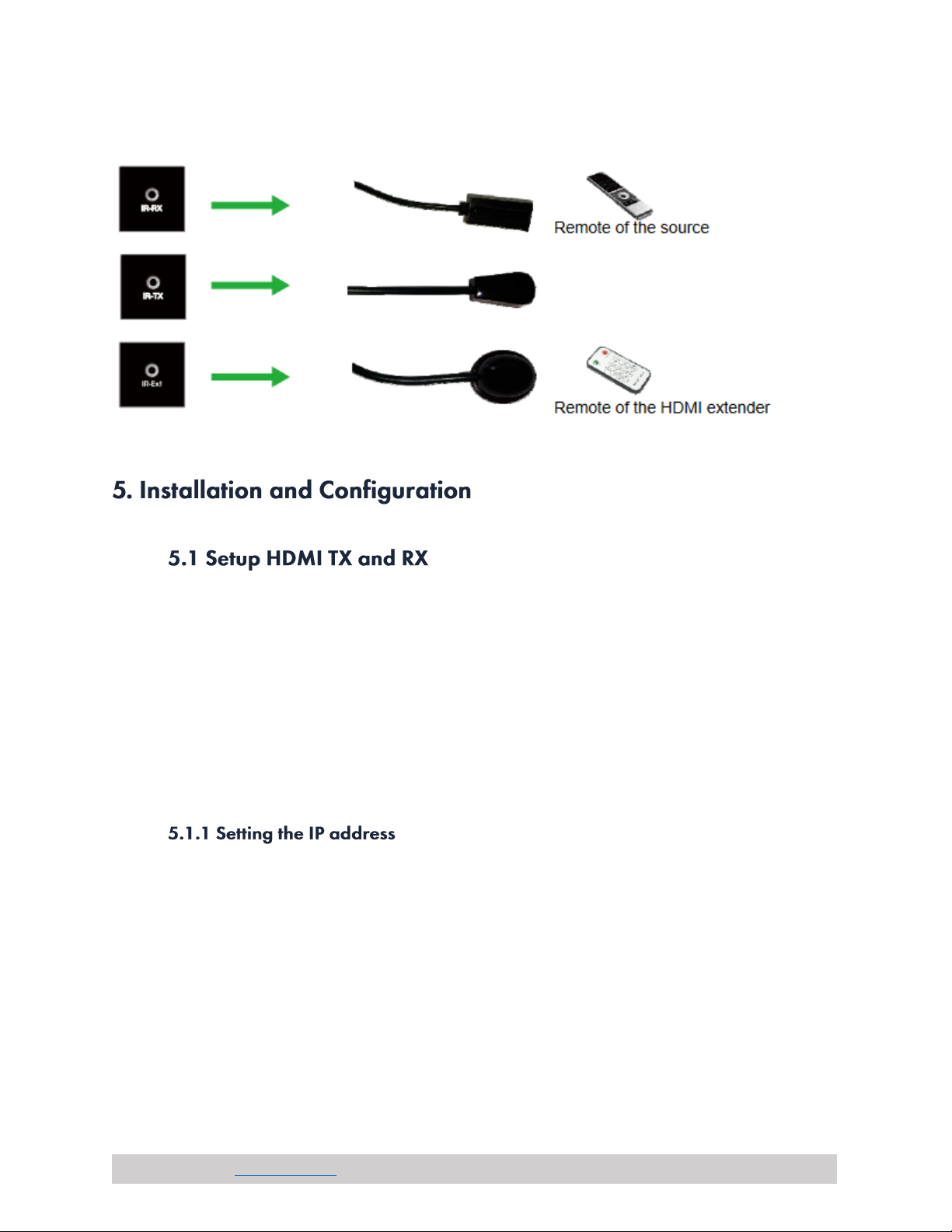
•Wide-band IR pass through to control the source (38khz to 56khz)
•By pass 2-way UART/RS232 (Up to 115200), use remote controller to select 8 group Baud
rate
•Supports one to one, one to many, many to one, many to many modes, with large cascade
•HDCP Compliant
•Support PC tool control
•DC 5V 1A power supply
Performance
Protocol
H.264 over TCP/IP
Video Format
Up to 1080P 60Hz
Audio Format
LPCM, Audio sampling rate 48kHz
Streaming Bit-rate
15Mbps
HDCP
1.4 Compliant
IR Frequency
38 ~ 56kHz
RS232 Baud Rate
Default 2400bps, 8 optional

(844) 200-1945 | [email protected] Page 5of 31 Copyright © Zenty AV
IP Setting & Group ID Setting
Default IP
Transmitter: 192.168.1.11
Receiver: 192.168.1.12
Group ID
Group 00 ~ Group 63
Request for Switch/Router
Supports IGMP, DHCP
Transmitter Connectors
Input
1 x HDMI Female Port
Output
1 x RJ45 Output | 1 x HDMI Looping Output
RS232
Phoenix RS232 Port
IR
IR TX Port (Supports 38 ~ 56kHz)
IR Ext Port (Supports 38kHz)
Receiver Connectors
Input
1 x RJ45 Input
Output
1 x HDMI Female Port Looping Output
RS232
Phoenix RS232 Port
IR
IR RX Port (Supports 38 ~ 56kHz)
IR Ext Port (Supports 38kHz)
Environmental & Power Requirements
Operating Temperature
-5° ~ 35°C (23°F ~ 95°)
Operating Humidity Range
5 –90% RH (No Condensation)
Power Supply
DC 5V/1A
Power Consumption
3W (Max)
Physical
Dimensions
Transmitter:
119mm x 79.5mm x 28mm
4.68” x 3.13” x 1.10”
Receiver:
119mm x 79.5mm x 28mm
4.68” x 3.13” x 1.10”
Net Weight
Transmitter: 0.62lbs
Receiver: 0.62lbs

(844) 200-1945 | [email protected] Page 6of 31 Copyright © Zenty AV
Frequency
Resolution
50Hz
576i
576P
720P
1080P
1080i
60Hz / 59.94Hz
480i
480P
720P
1080P
30Hz / 29.97Hz
1080P
24Hz
1080P
25Hz
1080P
VESA Resolutions
Frequency
Resolution
50Hz
576i
576P
720P
1080P
1080i
60Hz / 59.94Hz
480i
480P
720P
1080P
30Hz / 29.97Hz
1080P
24Hz
1080P
25Hz
1080P
•1 x Transmitter
•1 x Receiver
•1 x IR-TX cable
•1 x IR-RX cable
•2 x IR Ext Cable
•1 x Manual
•4 x screws
•4 x detachable mounting ears
•2 x Phoenix plugs for RS232 cable termination
•2 x Remote controller
•2 x Power adapter 5V 1A

(844) 200-1945 | [email protected] Page 9of 31 Copyright © Zenty AV
3). How to connect the IR Cable
When connecting point to point, no need to configure TX and RX.
When connecting point to many, many to point and many to many, please make sure every TX and
RX has unique IP and MAC address, every TX has unique group ID.
This over IP Extender has been assigned unique default MAC address for every TX and RX, so you
don’t have to set the MAC for the units.
You just need to set the IP address and Group ID following bellowing steps.
A). DHCP (Dynamic host configuration protocol)
If you are using a Switch that supports DHCP, please enable DHCP so that the Switch will assign a
unique IP for TX and RX, and you don’t need to change the IP for the unit’s manual.

(844) 200-1945 | [email protected] Page 10 of 31 Copyright © Zenty AV
B). Set the IP via web browser
If you are using a Switch that doesn’t support DHCP, please change the default IP for TX
(192.168.1.11) and RX (192.168.1.12) manually.
A HTTP server is embedded in each TX and RX. You can set up IP address for HDMI Extender via web
browser The default IP address of the TX is 192.168.1.11, user name: admin, password: admin.
The default IP address of the RX is 192.168.1.12
Step 1: Make sure the Transmitter and PC are in the same domain.
Access the Network Setting Control Panel in Windows and locate your Lan connection. Under
Windows 7, this can be done by clicking Start > Control Panel >Network Sharing center>Change
adapter settings > Properties >Internet Protocol Version4 (TCP/IPv4). Change the IP address field to
192.168.1.1 (0-255). After that press "OK" to save the configuration.

(844) 200-1945 | [email protected] Page 11 of 31 Copyright © Zenty AV
Step 2: Use an Ethernet Cable to connect the PC (or laptop) and the extender. the power LED for the
extender is red and the green status is blinking.
Step 3: Login in IE: 192.168.1.11 (default IP for TX) or 192.168.1.12(default IP for RX), You can
setup IP address for the TX and RX. TX requires user name: admin and password: admin
Please set IP address for each TX and each RX, IP: 192.168.1.XX (XX:1-255). All IP address for TX
and RX must be different and can’t be same as the PC’s address.)
Step 4: After selecting “Use DHCP” or reset the IP Address, click “Submit” (transmitter) or “update
DHCP” (Receiver).
Step 5: Click “Reboot”.
Step 6: Restart the extender after resting the IP Address.

(844) 200-1945 | [email protected] Page 12 of 31 Copyright © Zenty AV
Choose Group ID 00-63
1). Press “+” or “–” to change to the previous or next Group ID.
2). Press the No to change Group ID. For example, if you need change to 01, press “0”, then press
“1”.
Choose the Baud Rate
Press the Button, switch to Baud Rate mode, press “+” or “–” to change the Baud Rate.
F0 = 2400 (default)
F1 = 4800
F2 = 9600
F3 = 19200
F4 = 28800
F5 = 38400
F6 = 57600
F7 = 115200
3). How to choose the source:
For example, when the connection is:
Source (DVD1) - TX (TX1) - Gigabit Switch –RX (RX1) - TV1
Source (DVD2) - TX (TX2) - Gigabit Switch –RX (RX2) - TV2
Source (DVD3) - TX (TX3) - Gigabit Switch –RX (RX3) - TV3

(844) 200-1945 | [email protected] Page 13 of 31 Copyright © Zenty AV
The group ID of transmitters is:
TX1 (01)
TX2 (02)
TX3 (03)
If you need display Source on TV1, then just set Group ID of RX1 same as TX1: 01(see below picture).
Step 1: Make sure the Transmitter and PC are in the same domain. (Refer to 5.1.1)
Step 2: Use an Ethernet Cable to connect the PC (or laptop) and the Extender. the power LED for the
extender is red and the green status LED is blinking.
Step 3: Power on the TX or RX with 5V 1A power supply.
Step 4: Login in IE: 192.168.1.11 (default IP for TX) or 192.168.1.12(default IP for RX), TX requires
user name: admin and password: admin.
Step 5: Change the group ID at “Stream setting”, “00” means group “00” here which can be chosen
from 00 to 63.
Step 6: Click “Submit” (transmitter) or update (receiver).

(844) 200-1945 | [email protected] Page 14 of 31 Copyright © Zenty AV
When doing point to many and many to many, it requires a switch to distribute the sources. We
suggest you use the Switch that supports IGMP and DHCP. IGMP feature help to manage the group
ID which is related to switch the sources; DHCP allow the switch to assign an IP for TX and RX
automatically, please enable DHCP of the switch.
1. Connect the source device and the Transmitter unit with HDMI Cable.
2. Connect the HDMI looping output of the Transmitter to the local HDMI display.
3. Connect another HDMI display and the HDMI Receiver unit with HDMI Cable.
4. Connect the Transmitter and Receiver with Cat5e/6 cable
5. Connect the IR TX cable into “IR TX” port of the transmitter; Connect the IR RX cable into “IR RX”
port of the receiver. Then you can control the source at the RX side with IR.
6. Connect one RS-232 Cable from the PC or automation system to the RS-232 port on the
Transmitter; Connect one RS-232 cable from the Receiver to the RS-232 device to be controlled.
7. Power on Transmitter and Receiver with adapter 5V 1A.
NOTE: Insert/Extract cables gently.

(844) 200-1945 | [email protected] Page 15 of 31 Copyright © Zenty AV
1. Setting the IP address for Transmitter & Receiver and preparing the switch following the steps as
instructed above (5.1.1&5.2)
2. Connect the source device and the Transmitter unit with HDMI Cable.
3. Connect the HDMI looping output of the Transmitter to the local HDMI Display.
4. Connect the transmitter and the switch/router with cat5e or cat6 cable.
5. Connect all the Receivers and the switch/ router with Cat5e/6 cable.
6. Connect the HDMI displays and the HDMI Receiver units with HDMI Cable. 7. Connect the IR TX
cable into “IR TX” port of the transmitter; Connect the IR RX cable into “IR RX” port of the receiver.
Then you can control the source at the RX side with IR.
8. Connect one RS-232 Cable from the PC or automation system to the RS-232 port on the
Transmitter; Connect one RS-232 cable from the Receiver to the RS-232 device to be controlled.
9. Power on Transmitter and Receiver with adapter 5V1A, power on the switch with its adapter.

(844) 200-1945 | [email protected] Page 16 of 31 Copyright © Zenty AV
1. Setting the IP address for Transmitter & Receiver and preparing the switch following the steps as
instructed above (5.1.1&5.2)
2. Connect the source device and the Transmitter unit with HDMI Cable.
3. Connect the HDMI looping output of the Transmitter to the local HDMI Display.
4. Connect the transmitters and the switch/router with cat5e or cat6 cable
5. Connect the Receivers and the switch/ router with Cat5e/6 cable
6. Connect the HDMI displays and the HDMI Receiver units with HDMI Cable.
7. Connect the IR TX cable into “IR TX” port of the transmitter; Connect the IR RX cable into “IR RX”
port of the receiver. Then you can control the source at the RX side with IR.
8. Connect one RS-232 Cable from the PC or automation system to the RS-232 port on the
Transmitter; Connect one RS-232 cable from the Receiver to the RS-232 device to be controlled.
9. Power on Transmitter and Receiver with adapter 5V1A, power on the switch with its adapter.
10. Choose the source by Remote controller or Web browser as instructed
above (5.1.2)

(844) 200-1945 | [email protected] Page 18 of 31 Copyright © Zenty AV
The unit provides a path to pass through the RS232 signal, RS232 passes from TX to RX or from RX
to TX, connect to your RS232 devices, such as PC, IP Camera, Creston control panel, Smart Matrix,
printer and Scanner and so on. It works when TX, RX and your RS232 devices baud rate is the same.
The default baud rate of TX and RX is 2400 which is frequently used for most devices.
Login TX and RX with their default IP (TX: 192.168.1.11; RX: 192.168.1.12) to modify the Baud Rate
which range from default 2400 to 115200.
We provide the firmware to upgrade the units when it is necessary. Please follow these steps to
update the firmware.
Step1: Connect TX / RX to the PC with a short Cat5e cable
Step2: Power on TX/ RX with power adapter 5V1A.
Step3: Login TX or RX with their default IP (TX: 192.168.1.11; RX: 192.168.1.12) on web browser, TX
requires user name: admin and password: admin
Step4: Click “choose File” on the interface and find out the latest version firmware
Step5: Click “Upgrade”, the process will takes seconds, please DO NOT interrupt or power off the
units during the time.

(844) 200-1945 | [email protected] Page 19 of 31 Copyright © Zenty AV
It is available to recover the setting to factory setting, use a tiny pin to insert
the reset hole and hold about 10 seconds, when the unit is connected
Step 1: Make sure the Transmitter and PC are in the same domain. (Refer to 5.1.1)
Step 2: Open the PC Tool.
Step 3: Click “Start Scan”.

(844) 200-1945 | [email protected] Page 20 of 31 Copyright © Zenty AV
Step 4: Choose the TX or RX Name
Upgrade for TX:
Step 1: Click “Firmware Upgrade”.
This manual suits for next models
3
Other Zenty Network Hardware manuals
Popular Network Hardware manuals by other brands

TP-Link
TP-Link M7350 Quick installation guide

Lorex
Lorex LNK7000X Series Quick connection guide

Juniper
Juniper JSA5800 Hardware guide

Texas Instruments
Texas Instruments TPS23851EVM-001 user guide

Matrix Switch Corporation
Matrix Switch Corporation MSC-2HD2432L product manual

National Instruments
National Instruments NI WAP-3701 user manual