Zenza Bronica SQ-Am User manual

Congratulations on your choice of the Zenza Bronica SQ-Am single lens reflex camera which has been
developed to provide the user with high quality performance, simple handling convenience and extremely
useful versatility plus automatic motorized film winding and shutter cocking operations suitable for the
professional photographer.
Although the Zenza Bronica SQ-Am has been designed exclusively for motorized operations, it has, also,
been developed as a complete modular "system" camera possessing complete interchangeability with the
interchangeable lenses and accessories developed for the SQ and SQ-A models, on which the SQ-Am is
also based, and, therefore, provides the user with a very high degree of motorization in daily operations, in
addition to automatic film winding and shutter cocking actions. Although instructions following are based on
a standard combination consisting of the SQ-Am main body with Zenzanon-S 80mm lens, Film Back SQ 120
and WaistLevel Finder S, the choice of the lens, film back and finder is left to the discretion of the
photographer, who should choose those items best suited to the type of assignments contemplated.
To obtain best results from the Zenza Bronica SQ-Am, may we suggest that you read this instruction
manual through carefully, before you even touch the camera, as your pleasure in using the camera will be
even greater if you thoroughly familiarize yourself with its working parts before loading your first roll of
film.
CONTENTS
Specifications of the ZENZA
BRONICA SQ-Am.........................................
Parts of the ZENZA BRONICA
2
4
7
8
9
10
11
11
13
13
16
17
17
18
19
20
21
22
17. Interchanging Finders................................
23
18. Waist-Level Finder and
Interchanging Magnifiers..................................
23
19. Focusing Adjustments...............................
25
20. Distance Scale and
Depth of Field Scale........................................
26
21. Infrared Photography.................................
27
22. Flash Photography....................................
27
23. Multiple Exposures....................................
28
24. Mirror Lock-Up...........................................
29
25. Remote Control Operations......................
32
26. Use of External Power...............................
33
27. Interchanging Focusing Screens..............
34
28. Attachment of Neck Strap.........................
35
29. Facts about the Battery.............................
36
30. Pointers on Shooting.................................
37
31. Care of the ZENZA BRONICA
SQ-Am............................................................
38
32. Depth of Field Tables................................
40
33. Specifications of Zenzanon-S
Lenses.............................................................
41
SQ-Am.........................................................
1. Loading the Batteries.............................
2. Battery checking.....................................
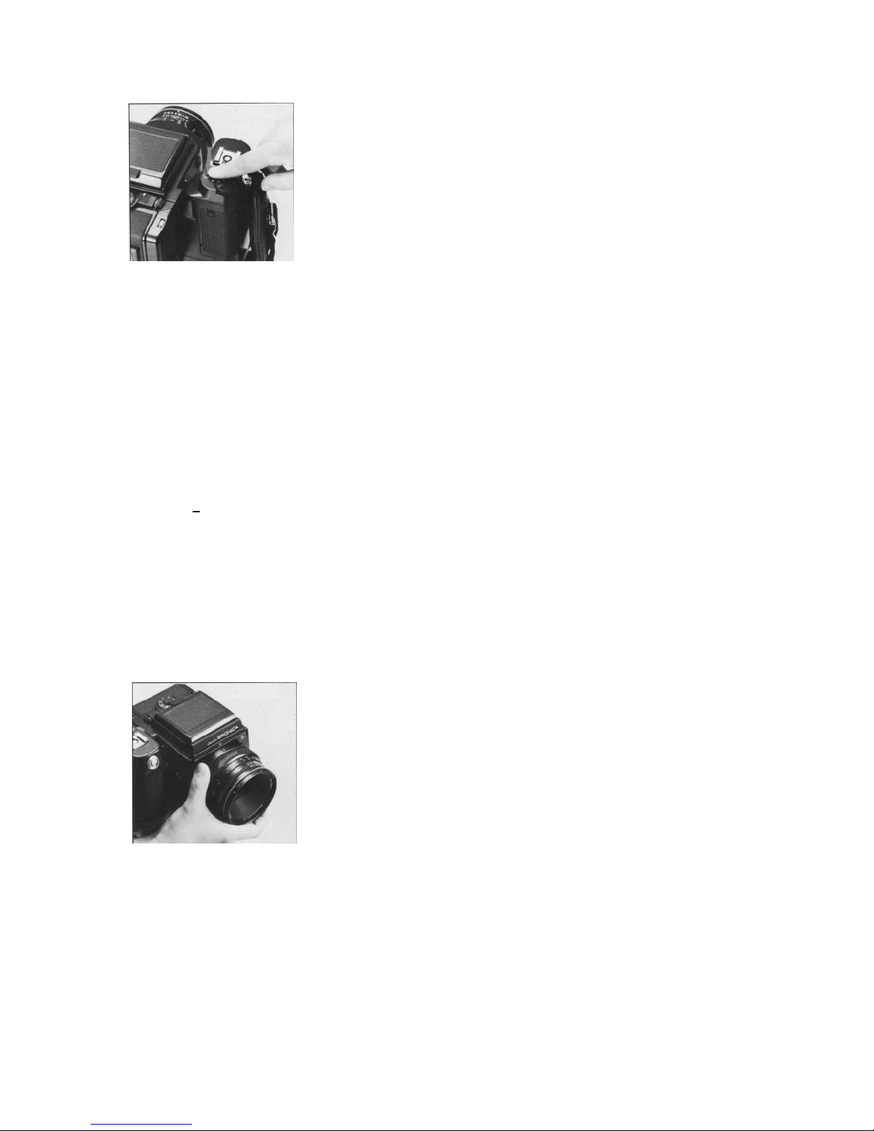
3. Exchanging Lenses................................
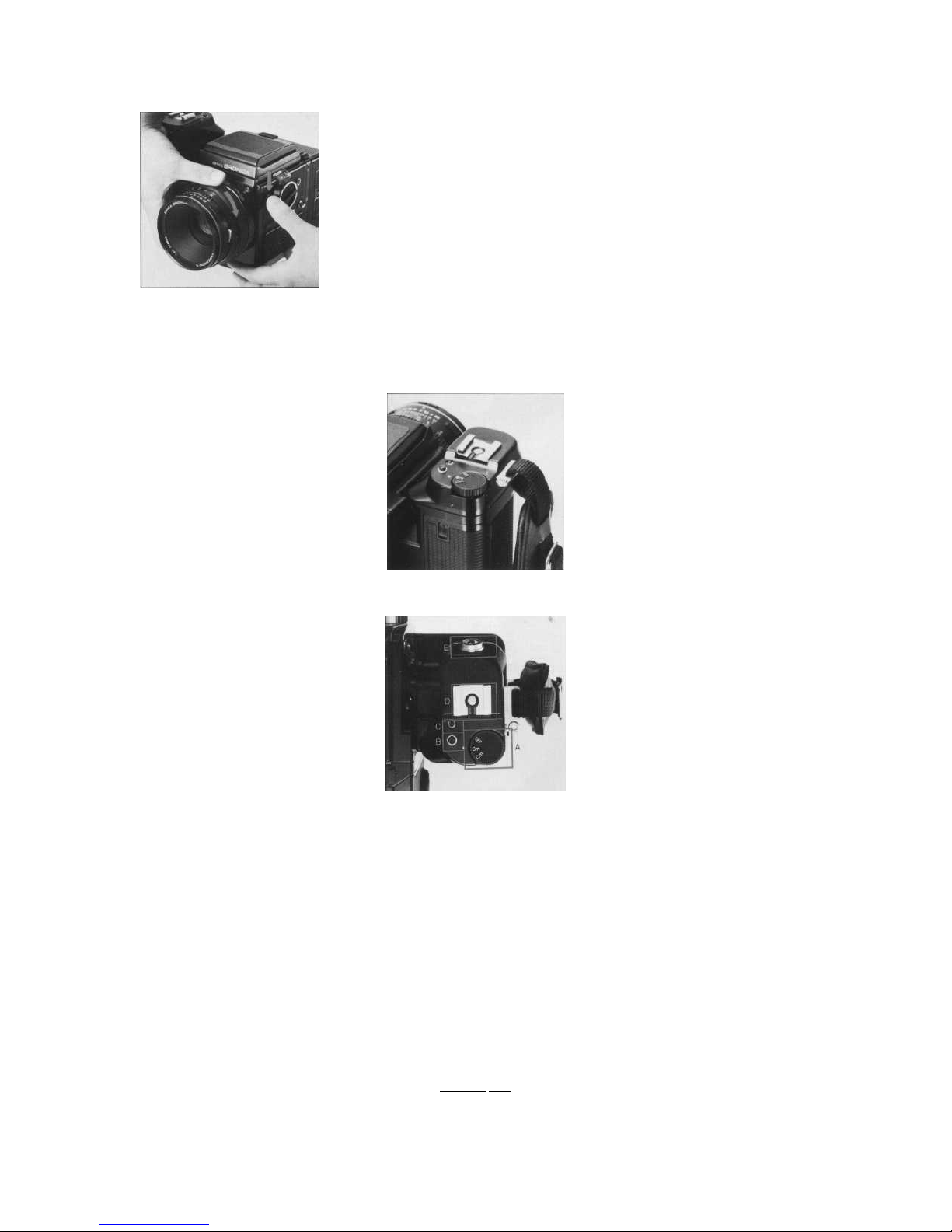
4. Functions on the Hand Grip...................
5. Shutter Release Warning LED..............
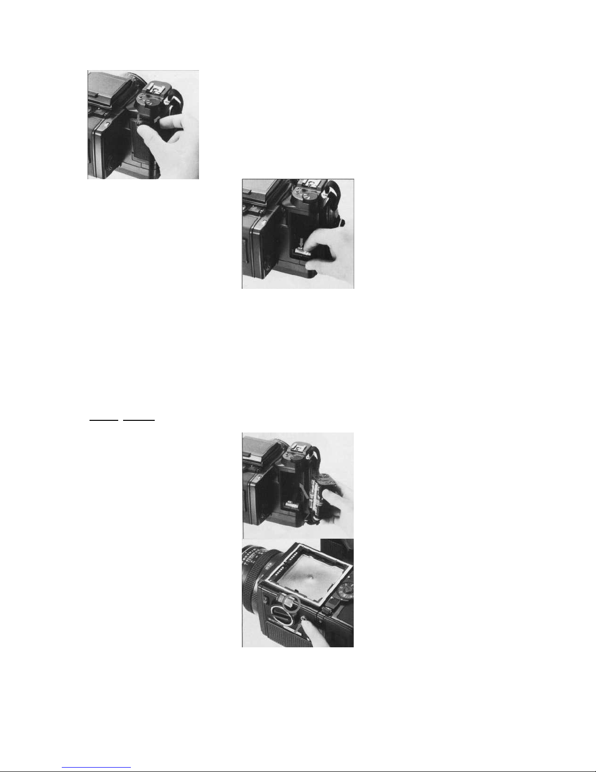
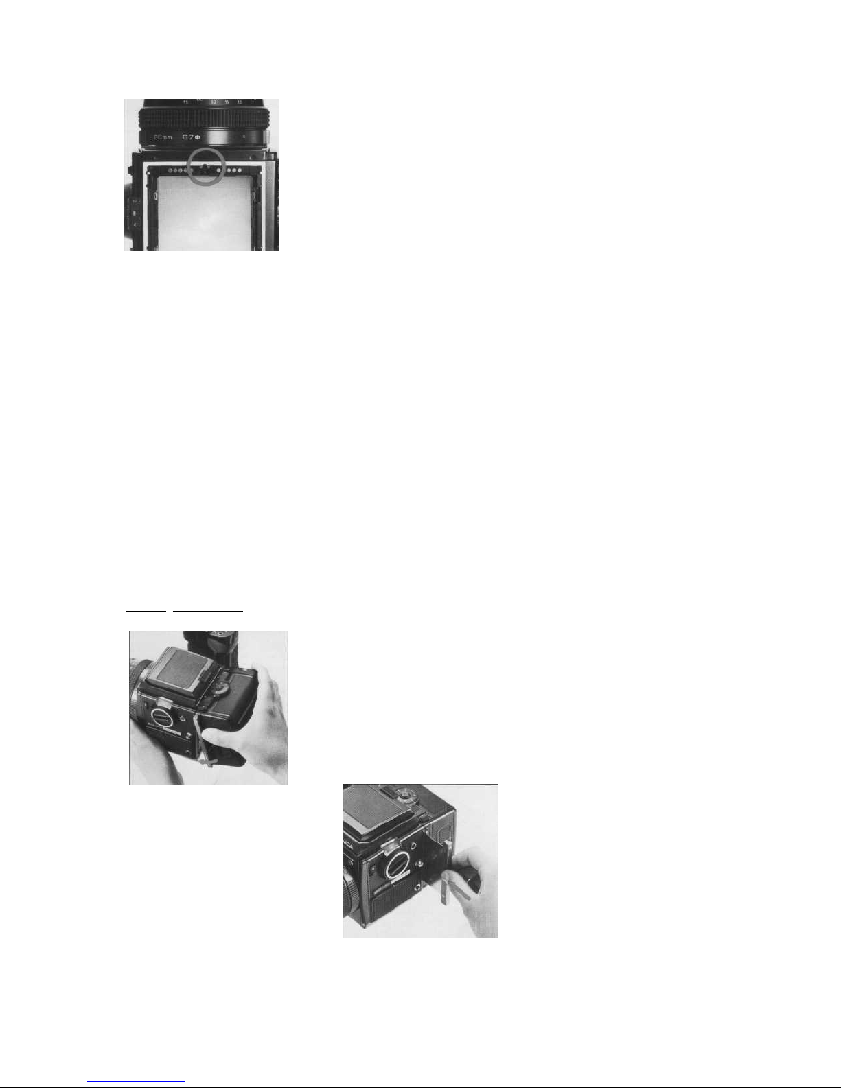
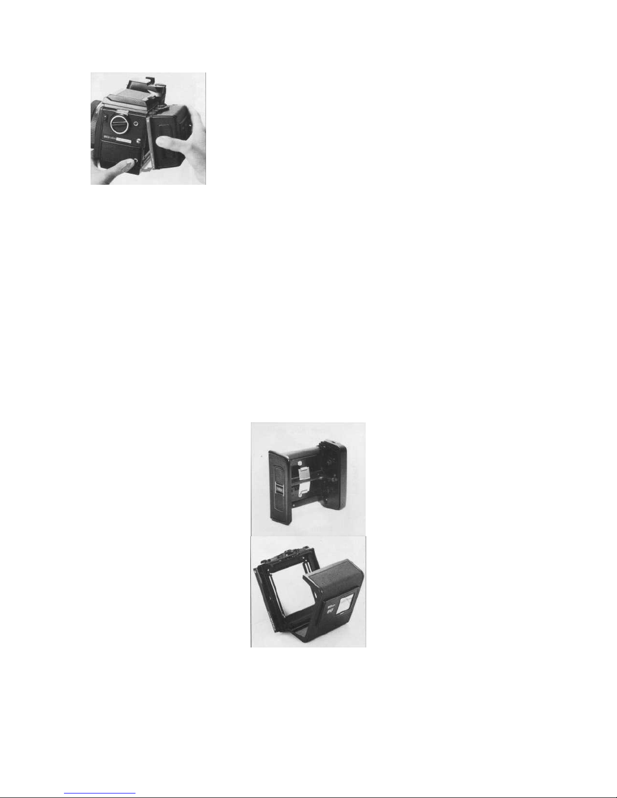
6. Attachment and Removal of
Film Back..............................................
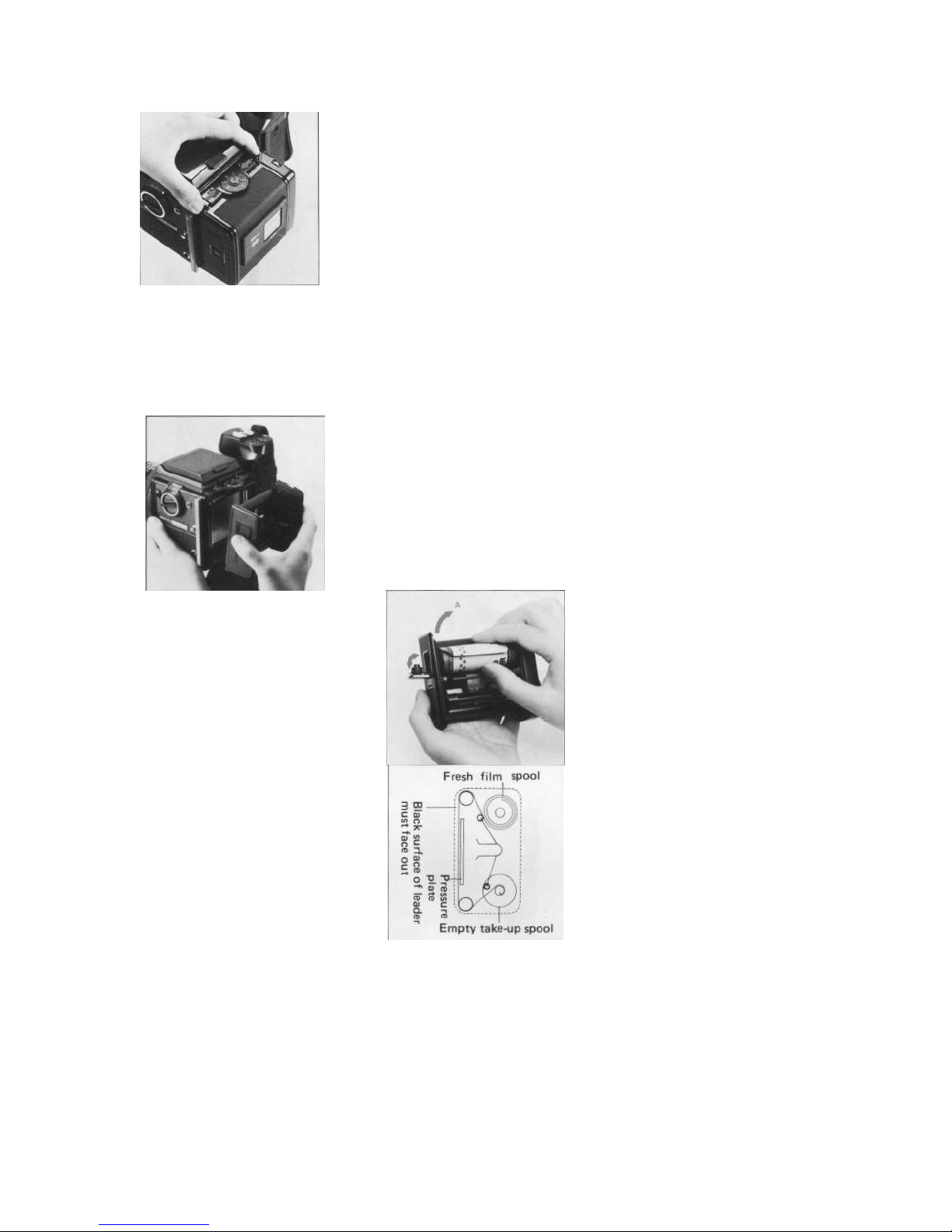
7. Construction of Film Back......................
.8. Film Loading...........................................
9. ASA/ISO Film Speed Dial......................
10. Film Type Indicator Frame.....................
11. Auto-Winding and Shutter Cocking ..
12. Exposure Counter..................................
13. Film Unloading.......................................
14. Setting the Shutter Speed Dial..............
15. Time(T) Exposure..................................
16. Setting the Aperture...............................
Specifications of the ZENZA BRONICA SQ-Am
Type
6 x 6cm format auto-winding lens shutter single lens reflex camera, with interchangeable lens,
Frame size
film back, finder and focusing screen systems.
55.6 x 55.6mm
Film
120 roll film (12 exposures);
Standard lens
220 roll film (24 exposures);
135 roll film in film cartridges; and Polaroid
®
Land Pack films.
(Exclusive film backs for each film type.)
Zenzanon-S 80mm F2.8; interchangeable type lens; six elements in four groups; multi-layer
Filter size
anti-reflection coated; 51
°
angle of view; F22 minimum aperture; and minimum 0.8m focusing
distance.
67mm diameter on 50mm to 250mm lenses; and 95mm diameter on 40mm and 500mm lenses.
Lens mount
Exclusive four-claw Bronica SQ bayonet mount.
Focusing adjustments
Helical focusing system built into each lens.
Lens diaphragm
Fully automatic instant reopening lens diaphragm action; equal-distant aperture scale gradua
Shutter
tions.
Electronic control SEIKO #0 between-lens leaf shutter; shutter speeds 8 sec. to
1/500 sec.,
Film winding
without intermediate settings, plus T (time exposure); mechanical control 1/500 second.
Motorized automatic film winding action.

Multiple exposure
Multiple exposure possible with multiple exposure lever on camera main body.
Mirror lock-up
Mirror lock-up possible with the mirror lock-up switch lever on the camera main body, with
Mode selection
two settings -
S
- Mirror returns automatically after shutter release action.
C
- Mirror stays locked up for continuous mode operation.
Mode changes with mode selector switch on the handgrip, with three settings -
OFF - All power is switched OFF and the shutter is locked.
Sm
- Single mode operation (single frame exposed).
Cm
- Continuous mode operation (consecutive frames exposed).
Film back
Exclusive film backs for 120, 220 and 135 roll films and Polaroid& Pack film.
Daylight loading interchangeable type; with 'ASA/ISO film speed dial coupling to finder with built-in
exposure meters.
Finder
Interchangeable finder system.
Focusing screen
Interchangeable type. Standard type, supplied with camera, has split-image rangefinder spot
surrounded by microprism ring and full-area matte screen. Flash synchronization X-setting (for all speeds up to 1/
500 second).
Battery checking
Red-colored LED indicator lights up at the rear end of the shutter speed scale window when the
battery check button is depressed (for checking the electronic shutter 6-volt power source).
Batteries
Single 6-volt silver oxide or alkaline-manganese battery for the electronic shutter system;
Six AA-size alkaline-manganese or NiCd batteries for the motor drive system.
Firing speed
Continuous shooting or single frame exposures at the rate of 3 frames per 2 seconds (ap
proximately) is possible with the fastest shutter speed.
Shutter speeds usable All shutter speeds can be used with auto-winding (also possible with finders having built-in ex
posure meters).
Number of frames
Approximately 500 frames can be exposed when fresh alkaline-manganese batteries are used (at
normal ambient temperature)
Others
Drive button, Over-load warning LED, Shutter release warning LED, Remote Control terminal, External
power terminal, Hot-Shoe.
Dimensions
144.5(wide) x 93(high) x 132mm(long) - SQ-Am main body only.
144.5(wide) x 109(high) x 179mm(long) - SQ-Am main body, with standard lens, Film Back SQ 120
and Waist-level Finder S.
Weight
960 grams (SQ-Am main body, without batteries)
1,925 grams (SQ-Am main body, with standard lens, Film Back SQ 120 and Waist-level Finder S but
without batteries.)
The above specifications are subject to change with or without prior notice.


111
Loading
the Batteries
A single 6 volt silver oxide battery or alkaline-manganese battery is required for the electronic control lens shutter. The
electronically-controlled shutter system will not work without loading the battery. The shutter will be mechanically
controlled when the battery is not loaded and will be released at 1/500 sec., regardless of the setting on the shutter speed
dial.
Six 1.5 volt AA-size alkalinemanganese or NiCd batteries are required for the motor drive system.
However, the performance noted in the specifications will not be possible when manganese batteries are used because of
their electrical characteristics.
*The batteries noted may be obtained at any photographic equipment or electrical applianceshop.

A. Set the mode selector switch to OFF. Then, slide the battery chamber button in the arrowindicated direction which will permit the
cover to be taken off.
The battery chamber cover is closed by, first, inserting the bottom end and then pushing the top end until it locks.
B. Taking out the upper battery holder will expose a lower battery chamber which is for the 6 volt battery of the electronic shutter.
Coincide the plus (+) and minus (-) marks on the battery with similar polarity indications in the battery chamber, when inserting the
battery, and then push it in with your finger.
* The shutter will be mechanically-controlled at 1/500 sec. when the battery is loaded with polarity marks reversed.
121
Battery
Checking

C. The six AA- size batteries for the motor drive system must be loaded in the battery holder taken out, with their polarity marks
coincided to the indications on the holder. The battery holder in which the batteries have been loaded must be inserted into the
battery chamber in the arrow- direction indicated on the holder.
A. Set the mode selector switch to Sm or Cm and then depress the battery check button. If a red-colored LED lights up at the rear
end of the shutter speed scale window, the battery for the electronic shutter is loaded properly and there is sufficient power for
operations. * If the LED does not light up, (1) Mode selector switch is on "OFF" position, (2) the battery is not loaded properly or (
3) it is completely drained and should be exchanged.
B. The batteries for the motor drive system are checked by setting the mode selector switch to Sm or Cm and depressing the drive
button to check whether there is motor drive operation or not.
3.
E
x
changing Lenses
The Zenza Bronica SQ-Am will not operate properly unless the lens is attached. Furthermore, it will not be possible to attach
or remove the lens unless both main body and lens are in the "cocked" condition, with the cocking pin on the lens positioned
between the red-colored band and green-colored dot and the cocking pin of the body set to the green dot. When the cocking
pins are not located properly for attaching the lens, simply move the cocking pin of the lens to the green dot manually, with
your finger, and press the drive button to cock the lens shutter when the cocking pin of the main body is not located at the
green-colored dot.
A. To attach the lens to the body, align the orange dot on the camera main body and the red dot on the lens, and then insert the
lens fully into its mount. Rotate in the counterclockwise direction until it stops, with an audible click, which will indicate that it is
securely locked.

B. To detach the lens, press the lens release button down and, at the same time, rotate the lens in the clockwise direction until it
makes a full stop, at which point it will be possible to detach the lens.
4.
Functions on the Hand-Grip
A. The mode selector switch has three settings, or OFF, Sm and Cm. When set to OFF, all power is switched OFF and autowinding,
lens shutter operation and the built-in exposure meter of attached finders will not function. When set to Sm, there is single
exposure operation and when set to Cm, there is continuous exposures while the shutter release button is depressed.
B. The drive button is used to set the loaded film to the first frame to be exposed, after it is aligned to the start-mark, to advance
the film for multiple exposures, etc.
C. When there is abnormal overload on the motor during film winding operations, etc., the motor will stop and the redcolored
overload warning LED will light up. Therefore, move the mode selector switch to OFF, check for the cause of the overlaed and
rectify it. Then, set the mode selector switch to Sm or Cm and it will be possible to continue shooting.
OFF, check
forthecauseof
the overload and rectify it. Then, set the mode selector switch to Sm or Cm and it will be possible to
continue shooting.
D. The accessory shoe is a hot shoe type which means that electronic flash units with proper terminals can be used without
connecting cords. However, the contact cover on the hot shoe must be removed, first, when attaching electronic flash units.
E. Depress the shutter release button gently, with the ball of the finger.
When the shutter release button is stroked gently and smoothly, it will be possible to confirm the shutter speed setting in the
viewfinder area of the AE Prism Finder S, when it is attached.
5
Shutter Release
Warning
LED

In the following cases, the shutter will not be released and a shutter release warning LED will light up, outside the screen area, in
the top center of the finder:
1 . Dark slide is inserted.
2. Lens is not attached properly. (Same with automatic extension tubes, too.) 3. Lens release button is depressed.
4. Film is not advanced. (Same when exposure counter is between "S" and "1 ".) 5. Batteries for motor drive operation does not
have sufficient power.
The film back is a film chamber that can be attached or detached freely, thus permitting free exchange of film types even during
shooting sessions.
The film back is fully coupled to the camera main body, upon attachment. Therefore, the shutter will not be released, even when
the shutter release button is depressed if the film back is attached with the film still not advanced properly, and the shutter
release warning LED will light up instead. The drive button should be used, in this case, to advance the film one frame.
On the other hand, should the drive button be depressed when a film back is attached with film advanced properly and, therefore,
in condition for photography, the film will not be advanced.
Thus, it is possible to choose the film type most suited to the shot, even midway in the roll. An ASA/ISO film speed dial is available
on the film backs and can be used for setting the film speed of the film loaded in the film back, as there is automatic
coupling when finders with built-in exposure meters are attached on the camera body. This will, of course, be very convenient
when using films of different sensitivities in the film backs.
* Make full use of the interchangeable film back. 1. Color and black-and-white, in different film speeds, can be shot, as required.
2. Continuous shooting is possible if sufficient preloaded film backs are available. 3. Don't waste unsuitable film used in a previous
session but simply load up a new film back with the required film type. 4. A Single SQ-Am can be used by many in the studio or at
home, by using additional film backs.
* Film backs are available optionally. Therefore, the type meeting the requirements of the photographer should be chosen.
161
Attachment
and Removal of Film Back

A. To attach the film back to the camera main body, simply insert the latches at the upper end of the film back into the
attachment openings at the upper end of the camera main body. Then, press the lower end of the film back against the body
until it locks securely.
*The dark slide must be withdrawn from its slit, upon attachment of the film back to the main body, as otherwise the shutter
cannot be released. Furthermore, there is danger of the film back accidentally becoming detached from the main body, should the
dark slide be r
B. To remove the film back from the camera main body, insert the dark slide into the dark slide slit, as illustrated, with the O mark
on the dark slide at the top end. Push it all the way in.
left in its slit while the camera is being carried. Therefore, make it rule to withdraw the dark slide promptly upon attaching the film
back to the main body.
C. Depress the film back release button and the lower end of the film back can be removed, as illustrated. Simply shift the film back
up slightly and pull it away.
* The dark slide cannot be withdrawn from the film back when the film back is detached from the camera main body.
7. Construction of Film Back
8.
Film Loading

A. The film back consists of a film holder and a film back frame, with exclusive film backs available for 120 and 220 roll films.
The film holder has an insert or frame for loading film, as well as a built-in film winding mechanism.
B. The film back frame has a base with a dark slide slit and a back cover with an ASA/ISO film speed dial and a film type indicator
frame. The film back frame completely encloses the film holder and shields it from outside light, as well as connecting it to the
camera main body and also coupling with the finders with built-in exposure meter.
A. To open the back cover, squeeze the left and right back cover release buttons, in the arrow-indicated directions, at the same
time and the back cover will open.
B. The film holder can be taken out for film loading, upon opening the back cover.
C. There are two spool holders on the film holder. The top one is for the fresh film spool while the bottom one is for the empty
take-up spool. The left-side shaft of spool holder can be opened by pushing the fresh film spool outward in the arrowindicated A
direction. Therefore, insert the right end of the spool on to the right-side shaft, which is fixed, and then close the left-side holder (
shaft) which will engage the spool.
* The spool holders on the left side will be locked securely, when the back cover is closed.
D. After loading the fresh film spool properly, draw out the leading end of the film and turn it across the film pressure plate (as
illustrated). Run it down and turn it over to the take-up spool. Insert the leading end into the slit of the take-up spool and wind
slightly until securely engaged.

* The inside black surface of the leader must face out when running across the pressure plate, in this case.
E. Lift up the hinged flap and rotate the manual film winder on the right side of the film holder in the arrow-indicated direction.
When the starting point, or arrow mark, on the leader is aligned with the triangular start-mark on the top left side of the film
holder, stop rotation.
F. Close the back cover, by pressing it firmly against the base of the film back, as illustrated. The back cover will automatically
close and lock. The same operation will close the back cover when the film back is detached from the main body.
G. Upon loading the film, set the mode selector switch to Sm or Cm and depress the drive button, which will place the first frame
into position for taking the picture.
The exposure counter will also change from "S" to "1" and the shutter will also be cocked.

19
ASA/ISO Film Speed Dial
H. When the film back is detached from the camera main body for film loading, the manual film winder is used for advancing the
film. The film will stop when it is in place for the first exposure, with the exposure counter also changing to "1 ". However, it will be
possible to rotate the manual film winder and, therefore, it should be rotated 2 or 3 times more, in order to take up any slack in the
loaded film.
* When loading 220 roll film in the Film Back SO 220, do not mistake the dotted line before the arrow mark for the start-mark.
* See the instructions supplied with Film Back SO 135 for proper use of the 135 roll film.
To set the film sensitivity of the film loaded in the film back, revolve the ASA/ISO film speed dial with a slight lifting action, as
illustrated, and set the film speed scale to the index. There are click-stops at 1/3rd increments, in this case. (The dial can be
revolved in either direction)
* The ASA/ISO film speed dial is automatically coupled to the finder with built-in exposure meter, when attached.
11O'
Film Type Indicator
Frame
1111
Auto-Winding
and Shutter Cocking

Upon loading the film, tear off the end flap from the empty film package and insert it in the film type indicator frame. This will help
you keep track of the film loaded in the film back, even when two or more film backs are used with different films. At the same
time, set the film speed with the ASA/ISO film speed dial, as it will come in handy when using the finder with built-in exposure
meter.
A. When the mode selector switch is set to Sm, the film will be advanced one frame and the shutter will be cocked, after which
motor operation will be suspended, each time the shutter release button is depressed and the picture taken. To take the next
picture, therefore, the finger should be lifted from the shutter release button and then used to stroke the shutter release button
once more.
B. When the mode selector switch is set to Cm, there will be continuous photography (with continuous auto-winding and shutter
cocking action), as long as the shutter release button is depressed.
* The mirror lock-up switch lever should be set to N, except when shooting with the mirror locked up. (See page 29 on Mirror Lock-
Up.)
(121
Exposure Counter
The exposure counter shows the number of frames exposed or, in other words, is an additive type. Starting from "S", the counter
on Film Back SQ 120 shows numbers from 1 to 12, while Film Back SQ 220 shows numbers from 1 to 24.
The letters "S", "12" and "24" are orange-colored while all other numbers are white.

113'
Film
Un
loading
A. After the 12th exposure of the 120 roll film (24th exposure of the 220 roll film), the film only will be advanced until the
remaining film and leader paper is wound up on the take-up spool.
Open the back cover when the motor suspends operations.
B. Remove the film holder and, while preventing the loose film from unwinding, take out the take-up spool. Seal the exposed film
and return it to its original box until development.
* Load and unload film away from direct sunlight and/or strong illumination.
(141
Setting
the Shutter Speed Dial

A. The shutter speed scale is viewed in its window over the shutter speed dial. The numbers on the scale are shutter speed
settings, with numbers 1 to 8S full numbers and numbers 2 to 500 fractions of a second. For examples, "8S" is 8 sec., "2S" is 2
sec. and "500" is 1/500 sec., but no intermediate setting between click stops are possible.
* The shutter is released at 1/500 sec., regardless of the setting when the battery is not loaded or is completely drained.
B. The numbers on the scale are color-coded in orange and white. Orange-colored numbers are full number settings of 1 second
and longer while whitecolored numbers are setting from 1/2 to 1/500 second. There is no B (bulb) setting. See the page 21 for
time (T) exposures.
1151
Time
(T)
Exposure
Time exposures are made with the time exposure lever on the lens, regardless of the setting on the shutter speed scale.
However, the lever is locked to prevent accidental movement and, therefore, must be unlocked for use.
Except when using the lever for time exposures, always shift it so that the letter "A" is visible on the lens barrel and tightly lock
its set screw to prevent accidental movement.

A. Unscrew the set screw on the time exposure lever until further revolution is not possible, which will permit the lever to be moved
freely.
B. Slide the time exposure lever and expose a red-colored "T" on the lens barrel. Depressing the shutter release button, in this
condition, will open the shutter. The shutter is closed by shifting the time exposure lever and exposing the letter
"A" once more.
•
,:,
the film will not be advanced to the next frame, in this case depress the drive button to advance the film.
the next frame, in
depress the drive button to
1161
Setting
the Aperture
A. The aperture ring is rotated, in either direction, to set the required f/number opposite the white index dot. The aperture ring
click-stops at the numbered settings. Intermediate settings are also possible.
* Intermediate settings cannot be used when the finders with built-in exposure meter are used.
B. All interchangeable lenses for the Zenza Bronica SQ-Am have fully automatic lens diaphragms which means that the focusing
screen is always viewed at the full aperture, with the brightest possible image. However, depressing the depth of field preview lever
will stop the lens diaphragm down to the preselected lens opening and permit the photographer to check the depth of field effect on
the focusing screen.
* The aperture ring must not be adjusted while the depth of field preview lever is being depressed.
17
Interchanging
Finders

I
Q' Waist-Level Finder and
Q Interchanging Magnifiers
A. The finder can be interchanged, with other optional finders, to match shooting conditions to photographic conditions. To attach
the finder, align the front end of the finder with the front end of the finder frame on top of the camera main body, as shown. Then,
gently lower the finder and, when well-seated, slide forward until it locks.
B. To detach, simply depress the finder release button, while, at the same time, sliding the finder backwards where it can be taken
up.
A. The focusing hood of the waist-level finder is opened by pushing up on the focusing hood catch at the rear end of the folded
waist-level finder.
* There is no standard finder for the Bronica SQ-Am, with the user having a choice of several finders. Instructions are based on
the waist-level finder because of its popularity.

B. The magnifier is flipped into viewing position, by simply sliding the release lever in the arrow-indicated direction. To store the
magnifier, simply push it down until it catches.
* The magnifier can be exchanged for one matching the eyesight of the user.
C. To close the focusing hood, first, push down the magnifier (if it is in viewing position). Next, press in both side frames, as
illustrated, and, at the same time, press the front frame back towards the rear. The focusing hood will automatically be folded
down.
D. The standard magnifier supplied with the waist-level finder has a power of -1 .5 diopters, which can be exchanged for others
with powers of -4.5, -3.5, -2.5, -0.5, +0.5 and +1 .5 diopters. These optional accessories should be purchased to suit the user's
eyesight, if necessary.
Simply rotate the magnifier frame in the counter-clockwise direction to unscrew.
Attach in the reverse manner.
(191
Focusing
Adjustments

A. The lens is focused on the subject, by rotating the focusing ring in either direction, while checking the effect on the microprism /
split-image rangefinder spot in the center of the focusing screen (standard type).
B. The central split-image spot splits the image into two, with the upper and lower halves separated horizontally when the lens is
out of focus. When in focus, however, the two halves will coincide with the displacement disappearing. The microprism ring
surrounding the central spot can also be used for checking the sharpness of the focused image, since the image will glitter when
the lens is not focused. The surrounding full-area matte surface can also be used for checking image sharpness.
1201
Distance
Scale and Depth of Field Scale
A. Distance scales on the Zenzanon-S lenses can be used for focusing at the required distance or finding the distance actually
focused. Simply rotate the focusing ring and set the required distance opposite the orange-colored index, which will adjust the lens
for the required distance.
B. There is an apparent zone of sharpness, both in front and back of the focused subject, which is known as the depth of field. The
depth of field scale shows the zone of apparent sharpness at any lens opening or distance and can be utilized for quickly and
simply ascertaining the depth of field. The depth of field scale is next to the distance scales and is made up of identical pairs of
apertures on both sides of the orange-colored distance index. These identical pairs of apertures indicate the distance that will be in
focus at these lens openings. For example, if
the 80mm lens is focused at a distance of 3m, it can be seen from the depth of field scale that the zone will extend from 2 to 7
meters (6 ft. to
23 ft.), when a lens opening of F22 is used.
See the depth of field table for the Zenzanon-S 80mm lens, on page 40.

121
I
Infrared
Photography
1221
Flash
Photography
In infrared photography, some adjustment must be made in the focus in order to retain sharpness on the film, because the
invisible infrared rays are longer in wave length than the visible rays used for focusing.
For infrared photography1. Use a R
filter or equivalent
with an infrared (black-and
white) film.
2. The red-colored line, next to the orange-colored distance index, is the infrared index.
3. After focusing in the normal manner, re-set the distance indicated by the orangecolored distance index to the infrared index, by
shifting the distance ring.
4. Follow instructions enclosed with the infrared film and filter and, to be on the safe side, make several bracketing shots. In
general, more exposure rather than less seems to be a safe guide.
A. Always use flash cords with a standard PC type plug. When detaching the flash cord, grip the plug firmly and pull it out straight,
instead of using a twisting action.
B. The lens shutter of the Zenzanon-S lens has a X-setting for flash synchronization, which means that electronic flash units will
synchronize at all shutter speed settings, up to the fastest 1/500 second.
This means, of course, that flash fill-in for daylight shots can also be made very easily.
A. To make multiple exposures, turn the multiple exposure lever in the arrow-indicated direction before exposing the first shot.
When the shutter release button is depressed, in this condition, the shutter will be released any number of times without advancing
the film.
Table of contents
Other Zenza Bronica Digital Camera manuals