1
1
2
2
3
3
4
4
5
5
6
6
A
B
C
D
Denna ritning är Z-Lyftens egendom och skyddad enligt internationellt gällande lag för copyright
och får ej utan Z-Lyftens skriftliga medgivande kopieras, delges eller obehörigen användas.
This drawing is property of Z-Lyften Produktion AB and is loaned subject to return upon demand. It is not
to be reproduced or used directly or indirectly in any way detrimental to the interest of Z-Lyften Produktion AB.
Drawing interpretation unless otherwise
specified.
All measures intends finished product
Title
Material
Dimension
Date
Weigh(kg)
Scale
Designer Checked by Approved by
Stock nr.
Drawing nr.
Sheet
Size
Revision
IS0 tolerances and drawing rules
Tolerance:
Surface finish:
Welding:
1
/
1
Drawn
A CARGOTEC BRAND
Used on:
ZEPRO
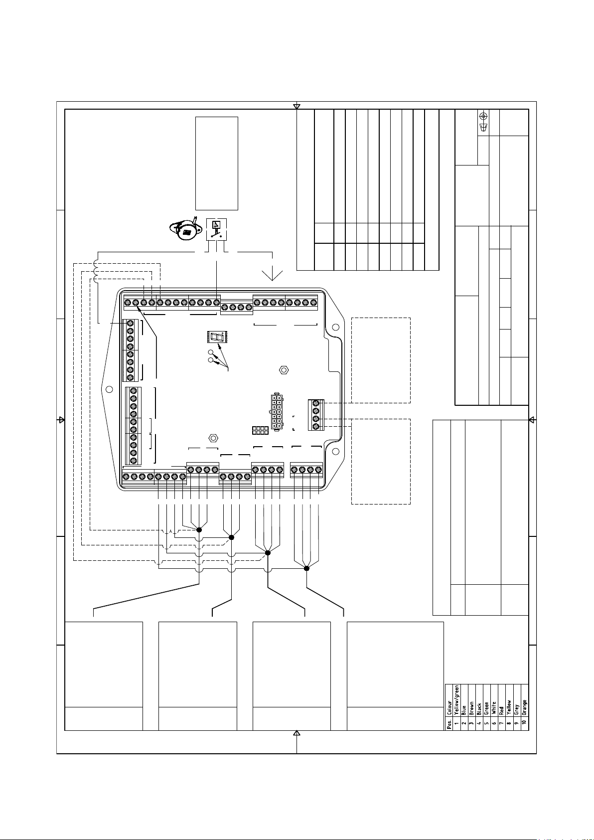
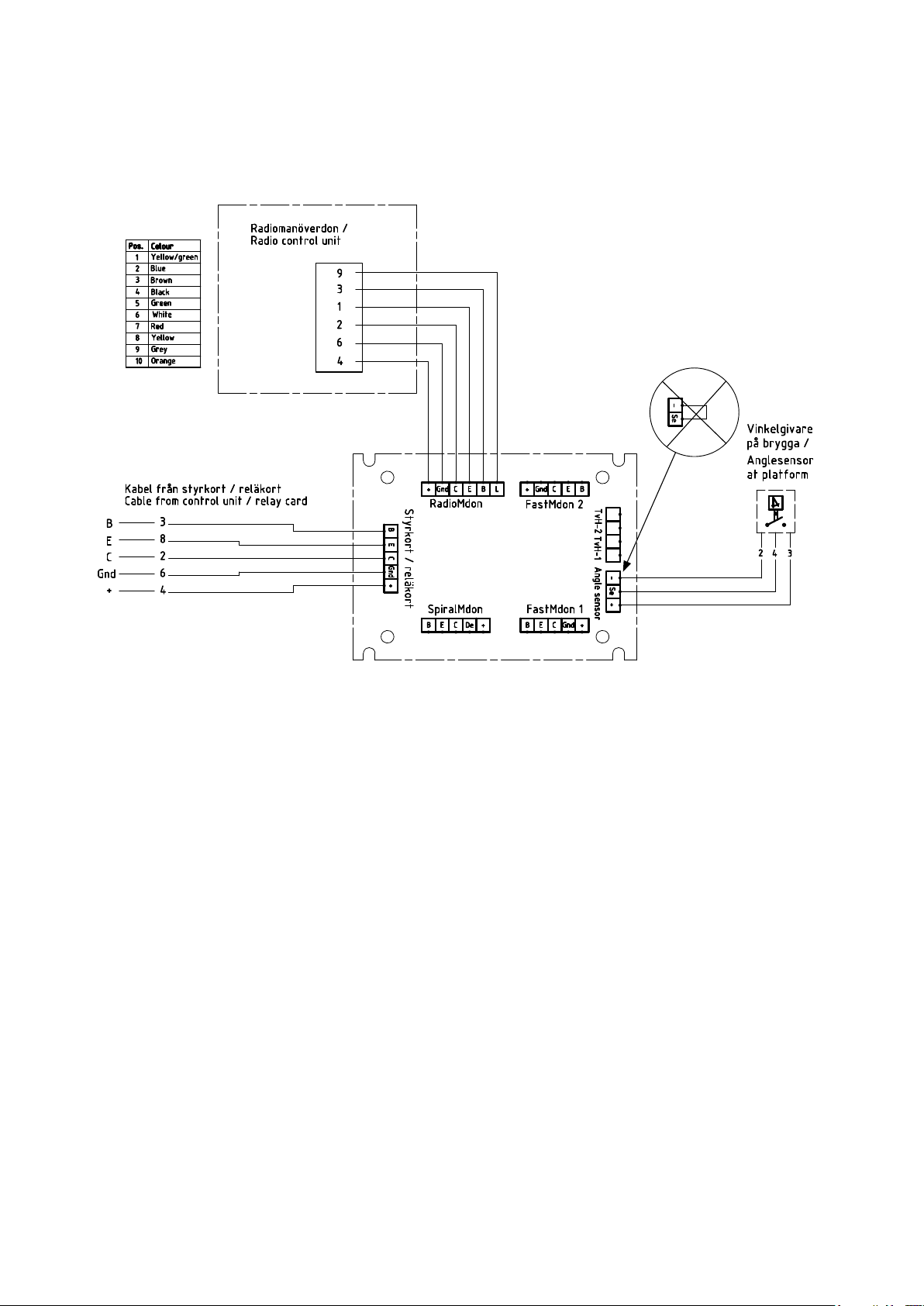
El & hydraulschema
E&H Schematic
Lyftar med 2H vinkelgivare
Lifts with 2H anglesensor
Z53534
75530TL
2016-07-04 MB MB PS PS
A2
-
--
1:1
Z-Lyften Produktion AB
-
-
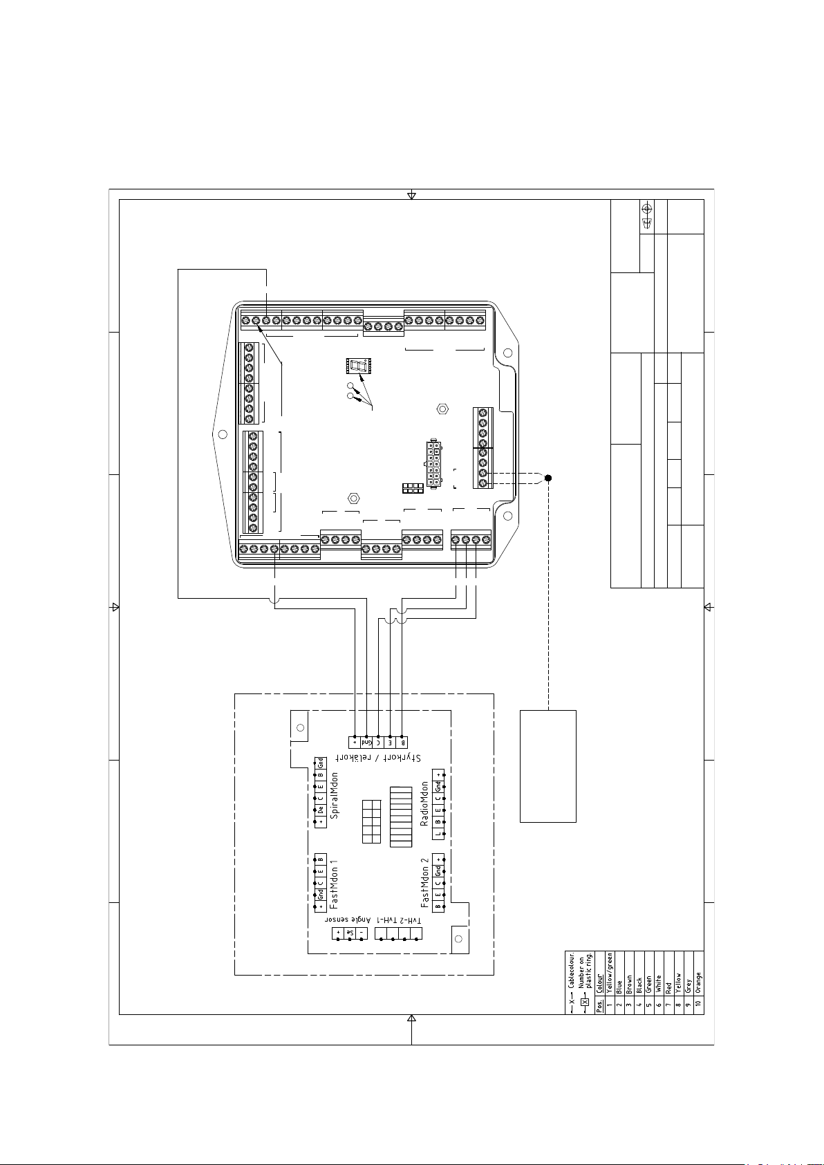
Ctrl 4
Spiral
Ctrl 3
Radio
Ctrl 2
Ctrl 1
Control Power
Sensor Power
Ground
IN OUT
Ai 1
Ai 2
Di 1
Di 2
Di 3
Di 4
Di 5
Di 6
PA-
PA+
CSPWR
CS
+
B
E
C
2H1
B
E
C
2H2
B
E
C
Lock
B
E
C
Lock
U7
U6
U5
U4
U3
U5
U4
U2
U1
U0
Ctrl 6
Out
In
GND/Spk-
LLED/Spk+
I-
I+
CR
CT
Ctrl 5
Indication
Se appendix in
installation manual
Outputs
Sensors
Not in use
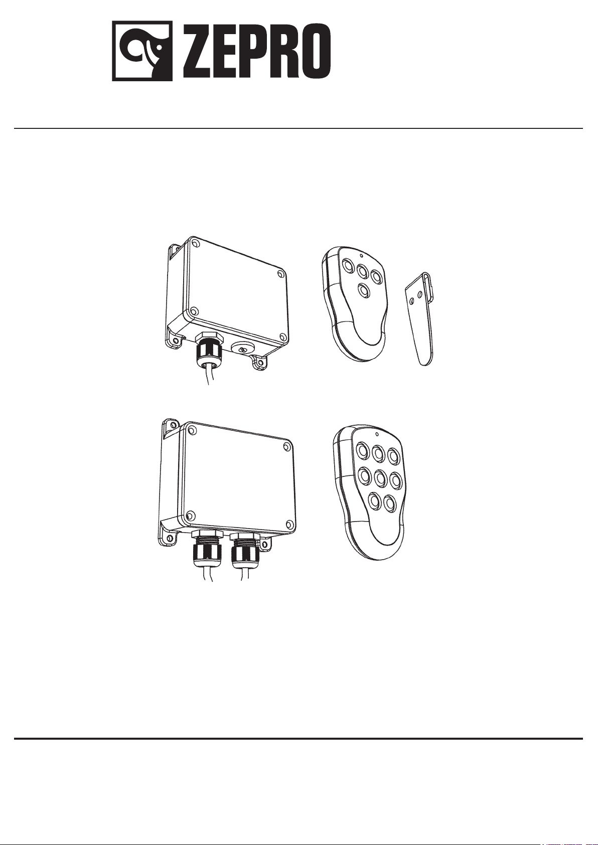
2-3 Knappsdon
---
2-3 Button Control
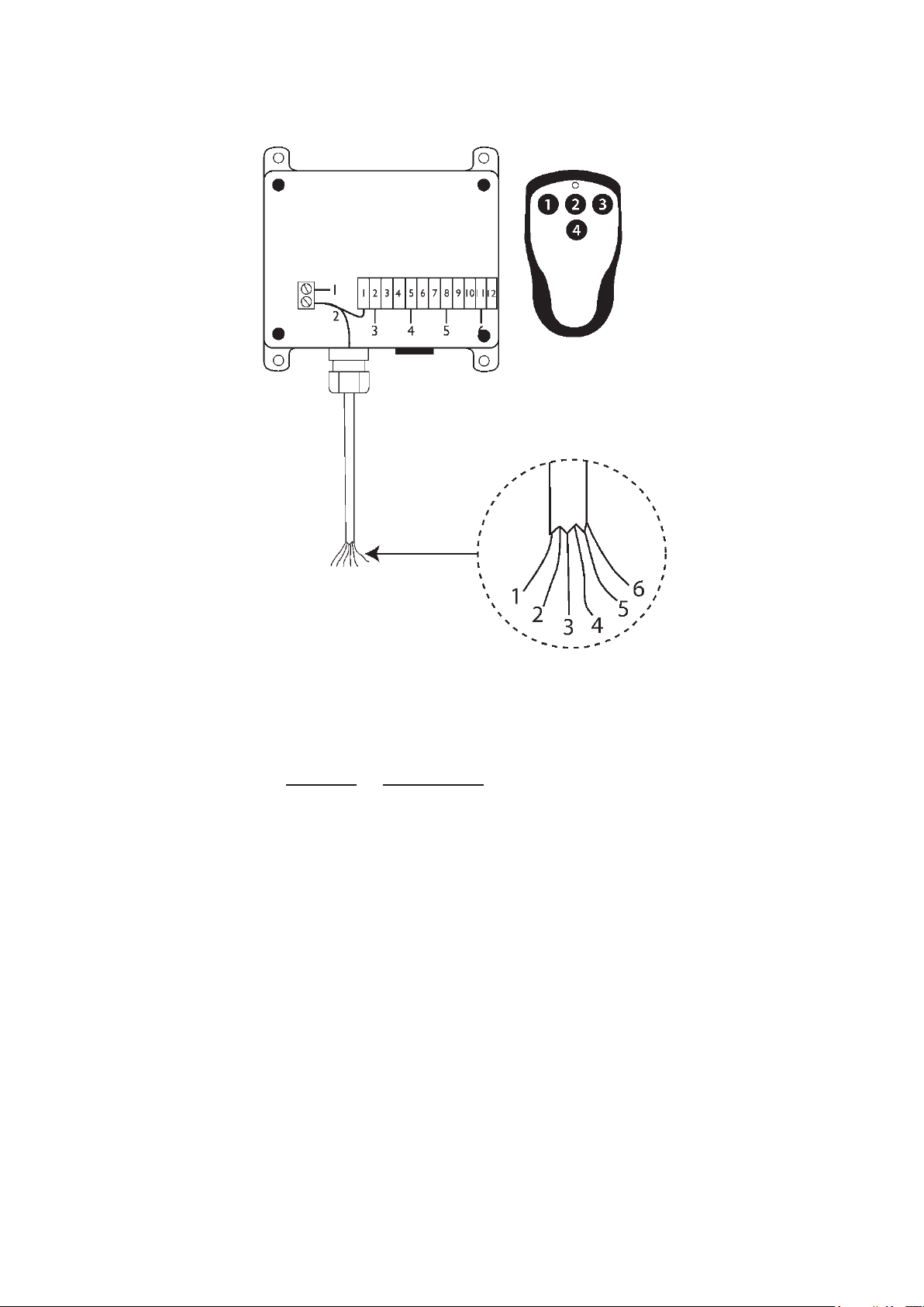
10
2
8
3
2
8
3
2
8
3
4
4
4
6
6
3
Ctrl 1Ctrl 2
2-3 Knappsdon
---
2-3 Button Control
Slädmanöverdons
anslutning*
---
Sledcontroller
connection*
Ctrl 4
Spiralmanöverdon
---
Spiral cable controller
Anslutningstabell / Connectiontable
Config Input Exempel på lyftmodeller (inte alla) /
Examples of liftmodels (not all)
1 Di2 ZHD,Z45,Z75,ZAHD,ZKZ,ZS,ZD,ZT
2-Se anteckningar / See notes***
3 - Se anteckningar / See notes***
6 Di3 SZHS
8 Di6 Z100
9 Di3 Z3N
12 -Se anteckningar / See notes***
13 Di3 ZHDN
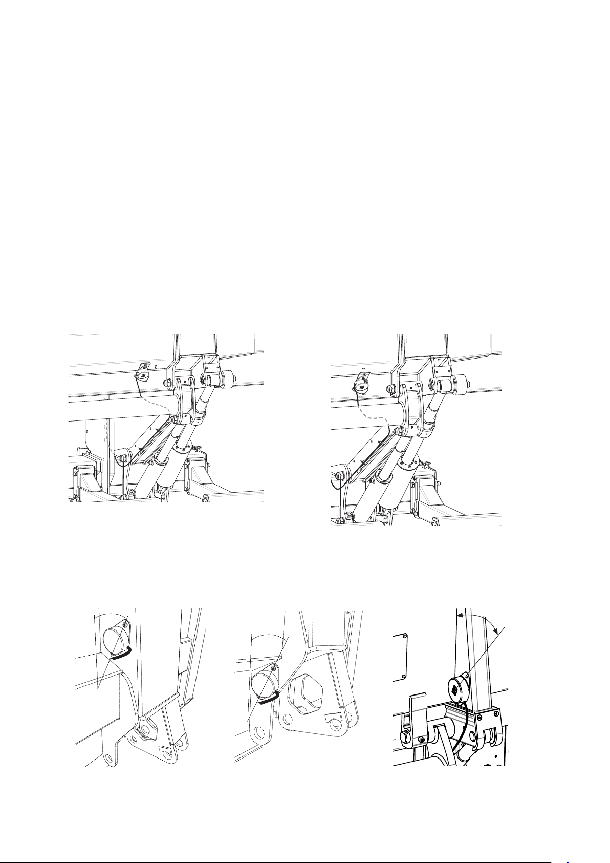
- Ingen vinkelgivare / No anglesensor
Se anslutningstabell nedan var
vinkelgivare ska monteras /
See connectiontable below
where to connect anglesensor
Jord anslutning finns ej på alla manöverdon / Earth connection is not present on all controls
4
Manöverdon
låsindikering**
---
Controller lock
indication**
Information
*
Beror på typ av lyft / Depends on the type of lift.
**
Anslutning av LED jord för manöverdon på CTRL1, 2
med låsindikering (ej spiral) / Connection for LED earth
used for controls connected to CTRL1,2 with LED
indicating lock (not spiral)
***
Vissa ZHD varianter främst som byggs med ett annat
arbetssätt på hydraulik / Certain ZHD variants that are
built on a different type of hydraulic design
2
Ctrl 3
Radiomanöverdon
---
Radiocontrol
3
4
2
8
3
9
46
5. Electric- and hydraulic diagram