ZERA TK326 User manual

Scanning Head TK326 2
TK326_MAN_EXT_GB_V102
Table of Contents Page
1. Safety Instructions............................................................................................................ 3
1.1. Important user considerations.................................................................................... 4
1.1.1. Danger references .......................................................................................... 4
1.1.2. User information, hints, references...................................................................... 4
1.1.3. Text markings...................................................................................................... 4
1. General description....................................................................................................... 5
2.1. Scanning of rotor marks............................................................................................. 5
2.2. Scanning of LED’s...................................................................................................... 6
2.3. Views of the TK326.................................................................................................... 7
2.3.1. Front view of the TK326.......................................................................................... 7
2.3.2. Rear view of the TK326........................................................................................... 7
2.4 Technical data of TK326............................................................................................. 8
2.5 Using the TK326 with holding arrangement.............................................................. 10
3. Service............................................................................................................................ 12

Scanning Head TK326 3
TK326_MAN_EXT_GB_V102
1. Safety Instructions
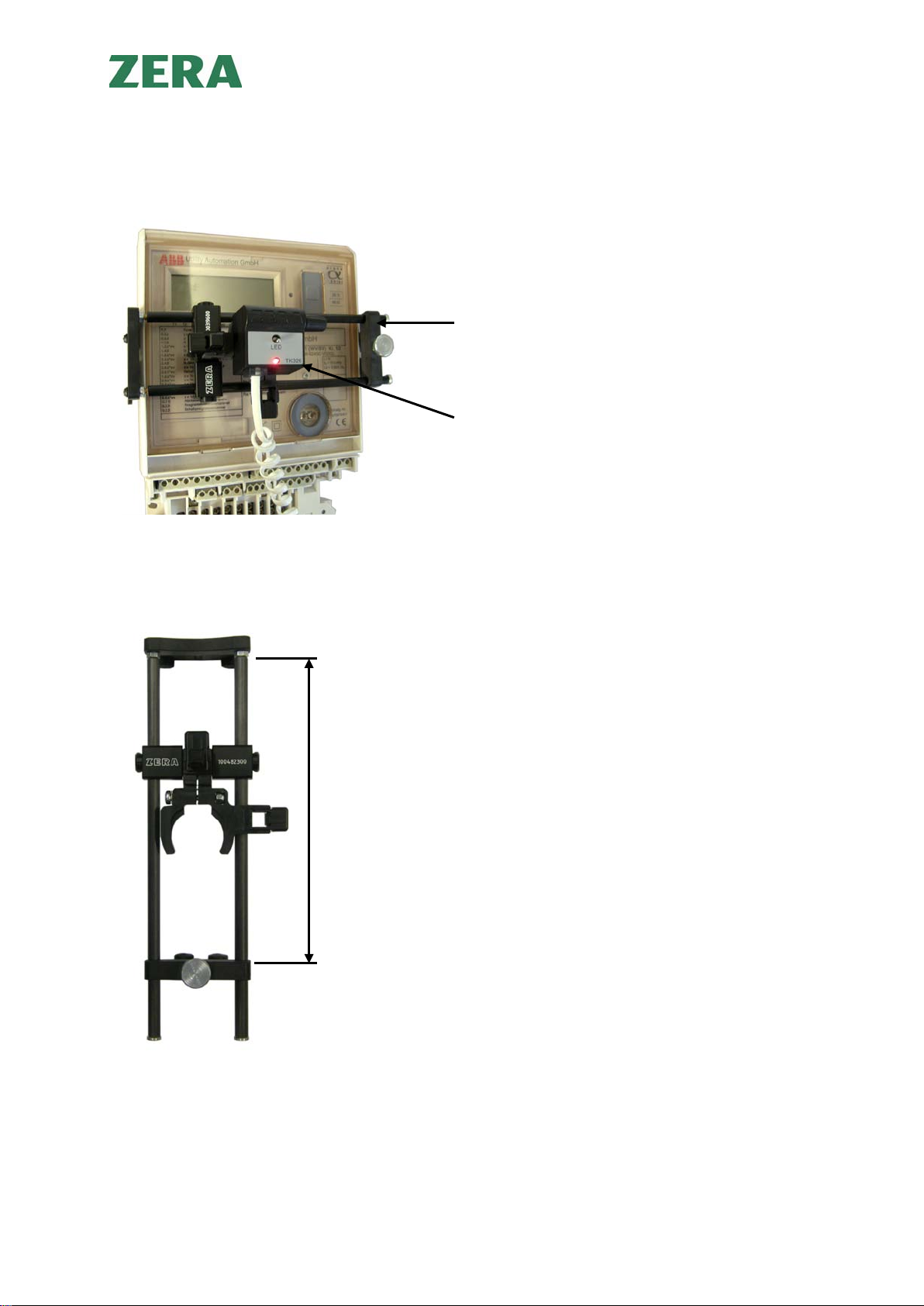
The scanning head TK326 is developed only for scanning of rotor marks and LED’s of electronic
meters.
It is not allowed to modify the TK326 in any way.
Only electrically skilled person (older than 18 years) having relevant education and experience
which enable him/her to perceive risks and to avoid hazard/damage which electricity can create, are
allowed to operate the equipment.
Every person putting this equipment into operation, operating or servicing the system should read,
understand and follow the user manual including all safety instructions. Use of equipment tools,
cables in a manner not specified may damage the protection provided by the equipment.
Also observe the local safety regulation, general guideline for accident prevention, general guideline
for safety engineering regulations.
If the units appears to be damaged or operates abnormally, protection may be impaired. Do not
attempt to operate it and report the defect or damages to the supervisor in-charge immediately. The
test operation has to be stopped until defects and damages have been repaired and removed.
This operation manual has to be kept close and accessible to the tester at any time.
The protective earth conductor of the meter test system should be connected with the
protective earth conductor of the main supply. This is necessary to safe against
unintended contact.

Scanning Head TK326 4
TK326_MAN_EXT_GB_V102
1.1. Important user considerations
1.1.1.Danger references
In this manual the red box with black text is used to warn the operator that ignoring the message or
action can cause hazard and/or damage to operator or property or test tools.
Red Box with text inside means that if ignored, damage to property or person can occur.
1.1.2. User information, hints, references
The blue box with blue text is used in this manual to provide information, hints and references to
further documentation to user.
Blue box with black text provides information, hints and references to further
documentation to use.
The gray box with black text is used in this manual to provide tips
1.1.3. Text markings
1. Numbers mark activities, which are to be accomplished in the indicated order.
-Hyphens mark general enumerating

Scanning Head TK326 5
TK326_MAN_EXT_GB_V102
1. General description
The scanning head TK326 is developed to scan rotor marks and LED’s of electronic meters.
If the TK326 is used to scan rotor marks, pulsed LED’s light up the rotor disk. So the reflected
light is pulsed as well and can be detected independent of the background light. The scanning
heads TK326 can detect every single switching edge of a pulse and allows the automatic
starting- and no load-test on ZERA test systems.
2.1. Scanning of rotor marks
For the scanning of rotor marks place the scanning head in front of the meter disk in approx.
35 mm distance. The switch on the rear side must be in the upper position (opposite to „LED“
see chapter 2.3.2.). Place the rotor disk in the middle of the overlapping light spots as shown
in figure 1. The scanning head uses blue LED’s to lighten the rotor mark having a much
stronger intensity than other available LED’s and guarantee the best contrast to detect all
known black and red (even transparent) rotor marks.
mark light spots disk
Figure 1
The sensitivity of the scanning head is adjusted by means of the potentiometer on the rear by
observing the monitoring LED.
If this diode is lit and does not go out, while passing a mark, the potentiometer must be turned
anticlockwise until the diode goes out, while passing a mark. Pay attention that the monitoring
diode does not give double pulses. In this case turn the potentiometer a little bit clockwise.

Scanning Head TK326 6
TK326_MAN_EXT_GB_V102
Comment for difficult scanning meters:
If the adjustment is difficult, place the scanning head a little bit closer or diagonal to the
rotor disk and adjust it again.
If wrong marks are detected additionally, place the scanning head a little further from the
rotor disk.
The density of the scanning head falls with rising of illumination of the room. It might be
advantageous to darken the room. Avoid direct sunlight.
2.2. Scanning of LED’s
For the scanning of LED’s place the scanning head in front of the LED in approx. 35 mm
distance. The switch on the rear side must be in the lower position („LED“ see chapter 2.3.2.).
The potentiometer of the TK326 has no influence on scanning. The scanning head is
positioned in front of the diode to be scanned in approx. 35 mm distance. The diode on the
rear of the scanning head flashes in time with the pulse transmission.
For difficult scanning meters:
The density of the scanning head falls with rising of illumination of the room. It might be
advantageous to darken the room avoid direct sunlight.

Scanning Head TK326 7
TK326_MAN_EXT_GB_V102
2.3. Views of the TK326
2.3.1. Front view of the TK326
2.3.2. Rear view of the TK326
Potentiometer
Interface
Pulse diode
Switch
Serial-No.
Part-No.

Scanning Head TK326 8
TK326_MAN_EXT_GB_V102
2.4 Technical data of TK326
Operating voltage: 12 V ±2 V DC
Current input: approx. 60 mA
Output: 12 V / max. 50 mA
Temperature range: 0 ... + 70° C
Connector: RJ10 4-pole
View from rear side
Dimensions: 37 x 40 x 41.5 mm (W x H x L)
Output circuit:
Pin 1 not used
Pin 2 0 V
Pin 3 Output
Pin 4 + 12 V

Scanning Head TK326 9
TK326_MAN_EXT_GB_V102
Scanning of LED’s
:
Wavelength: 450 ... 950 nm
Distance to meter LED: 25 ... 50 mm
Pulse data:
max. frequency 1000 Hz
max. rising time 20 µs
min. pulse width 100 µs
max. falling time 20 µs
min. pulse pause 400 µs
Squarewave 1:1:
max. frequency 1000 Hz
max. rising time 20 µs
max. falling time 20 µs
Squarewave 1:1, Amplitude modulation 8 kHz:
max. frequency 500 Hz
max. rising time 20 µs
max. falling time 20 µs
uncertainty of switching edge detection ±1 µs
Rotor marks scanning
:
wavelength LED in front 450 nm
distance to rotor disk 25 ... 45 mm
uncertainty of switching edge detection ±1 µs

Scanning Head TK326 10
TK326_MAN_EXT_GB_V102
2.5 Using the TK326 with holding arrangement
Examples for horizontal and vertical fixing at the meter
LED-Scanning
Holding arrangement for TK326 (standard)
TK326
Holding arrangement for TK326
(optional) up to
max. 220 mm

Scanning Head TK326 11
TK326_MAN_EXT_GB_V102
Scanning of rotor marks
Scanning of rotor marks (sideways)
at electrical meters with bell jar
Detail see
right picture
Holding
arrangement
TK326
Tension belt
Fixing of the
holding
arrangement
with tension
belt

Scanning Head TK326 12
TK326_MAN_EXT_GB_V102
3. Service
If you have technical questions, please contact our service department along with the following
information:
- serial-number of the scanning head (position see chapter 2.3.1.)
- commissioning number
- detailed description of the problem
This manual suits for next models
1
Table of contents