Zesto Audio Bia 200 Select User manual

1 | P a g e
Bia 200 Select
Class A Stereo Power Amplifier
Owner’s Manual
Please read carefully before
installing and operating this equipment
Zesto Audio
3138 Calle Estepa
Thousand Oaks, California 1360
805-807-1840
www.zestoaudio.com
george@zestoaudio.com
Made in the USA
Using US and mported Parts

2 | P a g e
Dear Music Lover,
I wanted to personally thank you for your purchase of my Bia 200 Select Stereo Power Amp.
I have loved music all my life – as a musician, record producer and audio engineer. That
makes me fussy about sound. That’s a good thing.
Each unit is built by hand with precision and pride to produce the most enjoyable listening
experience for you.
I am proud to put my name on it and honored to share this with you.
Wishing you many happy years of listening!
Sincerely,
-- George Counnas, President of Zesto Audio
FYI:
Zesto is Greek for hot
Bia (pronounced “by-ah”) is the Titan Goddess of force and power in
Greek mythology. The word bias comes from the goddess Bia.

3 | P a g e
Table of Contents
Thank You ……………………………………. Page 2
Table of Contents……………………………… 3
What’s in the box……………………………… 3
Warning and Caution…………………………. 4 - 6
Front and Rear Controls……………………… 7
Specifications …………………………….…. 8 & 9
Set Up-placement, cables…………………… 10
Power …….……………………………..……. 11
Tubes.…….……………………………...……. 11 -13
Bias Select Switch…….…………………… 14 & 15
How to use – Grounding & Turn on……… 15 & 16
Safety Tips- fuses………………………………. 17
Trouble shooting………………………………. 18
Warranty nformation………………………. 19
What’s in the box
Bia 200 Select Stereo Power Amp
4 KT150 Vacuum Tubes
4 ECC82 (12AU7) Vacuum Tubes
White glove for handling tubes
IEC power cable 6’
What’s not ncluded:
KT88, KT120, or KT170 vacuum tubes
Interconnect or speaker cables

4 | P a g e
Warning and Caution
WARN NG: The triangle with the lightning flash symbol displayed on the unit advises the user
of dangerous uninsulated voltage inside the product’s enclosure.
CAUT ON: To reduce the risk of electric shock, do not remove the cover. There are no user-
serviceable parts inside; it is recommended that only qualified personnel service this
component.
1. OWNER’S MANUAL: Before powering up the equipment, read all safety and operating
instructions and follow them as instructed. Retain the safety and operating instructions for
future reference.
2. ATTACHMENTS: Use only those attachments recommended by the unit manufacturer, as
others may cause hazards.
3. ACCESSOR ES: Do not place the unit on an unstable cart, stand, tripod, bracket, or table.
The unit may fall, causing injury to a person or damage to the unit. Mount the unit
according to the manufacturer’s instructions with the suggested mounting accessory.
4. WALL OR CE L NG MOUNT NG: Do not mount the unit on a wall or ceiling.
5. WATER AND MO STURE: Do not use the unit near water (for example, near a swimming
pool, bathtub, wash bowl, kitchen sink, or laundry tub) or in a damp environment (like a
basement or outside in the rain).
6. OBJECT AND L QU D ENTRY: Do not push objects of any kind into the unit through
openings as they could touch dangerous voltage points and short-out parts, possibly
resulting in a fire or electric shock. Do not spill liquid of any kind on the unit. If water or
any metal object (such as a paper clip, coin, or staple) accidentally falls inside the unit,
disconnect it from the AC power source immediately and contact Zesto Audio for further
instructions.
7. HEAT: Position the unit away from heat sources such as radiators, heat registers, stoves,
or other units (including amplifiers) that produce heat.
8. VENT LAT ON: Slots and openings in the enclosure create ventilation to protect the
component from overheating. All of these openings must remain unobstructed. Allow at
least 12 inches of clearance above the unit, 1 inch below and an opening behind the unit
for airflow. Do not place the unit on a bed, sofa, rug, built-in bookcase, or rack without
adequate ventilation.

5 | P a g e
. GROUND NG OR POLAR ZAT ON: As a safety feature, the unit may be equipped with a
polarized alternating current line plug in which one blade is wider than the other and a has
an additional grounding blade. This plug will fit into the power outlet only one way. If you
cannot insert the plug fully into the outlet, try reversing the plug. If the plug still will not fit,
contact a licensed electrician to update your outlet. Do not defeat the safety purpose of
the polarized plug.
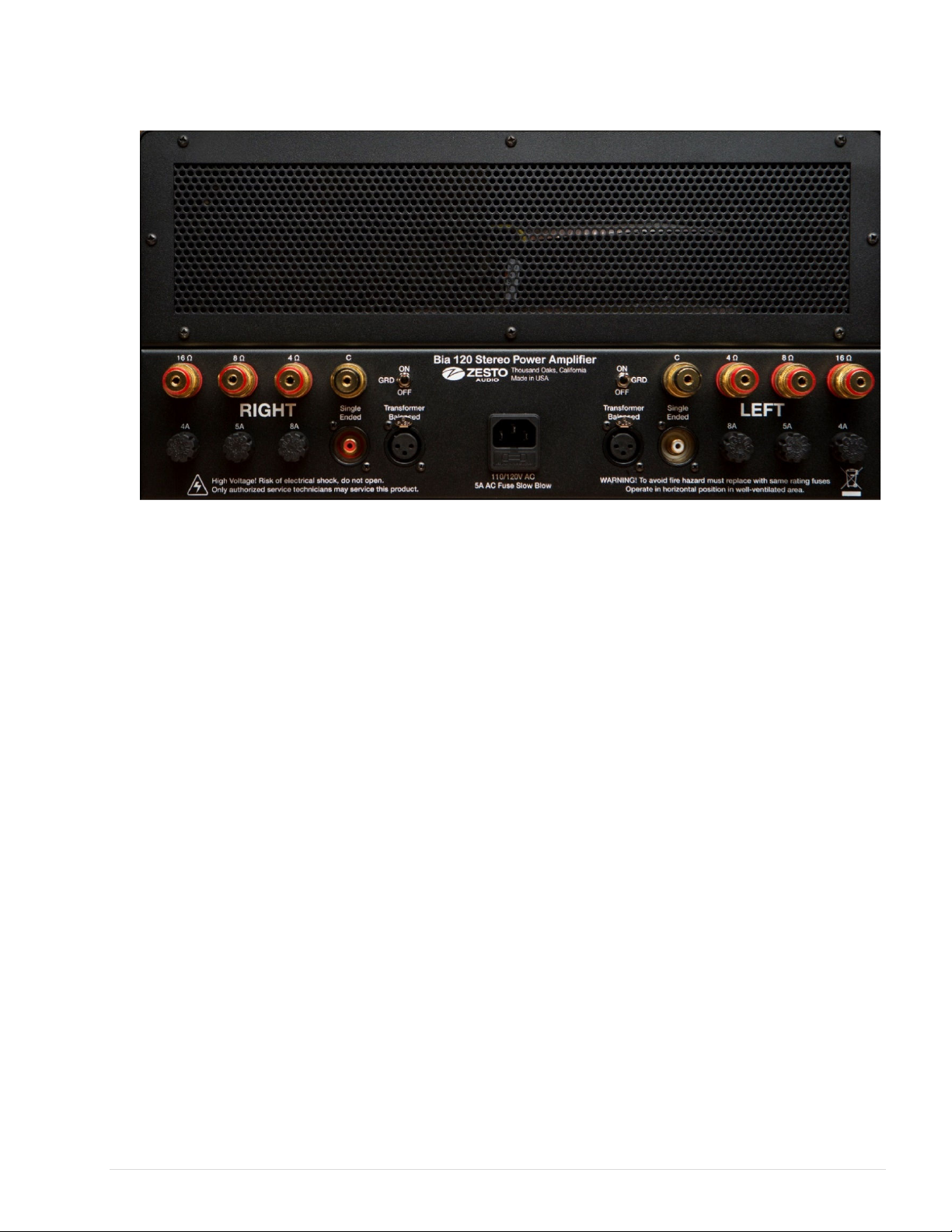
10. POWER SOURCES: Operate the unit only from the power source indicated on the
marking label on the back of the unit. If you are unsure of the type of power supplied to
your home, consult your unit dealer or local power company.
11. POWER CORD PROTECT ON: Arrange power supply cords so that they do not suffer
from foot traffic or pinching by items placed on or against them. Pay close attention to
cords where plugs enter the AC outlet and where they exit from the unit.
12. L GHTN NG: For added protection during a lightning storm or when the component is idle
for extended periods of time, unplug the unit from the wall outlet. This will help protect the
unit from lightning and power line surge damage.
13. POWER L NES: Do not locate an outside antenna system in the vicinity of overhead
power lines or other electric light or power circuits. When installing an outside antenna
system, take extreme care to avoid touching the power lines or circuits; contact with them
could be fatal.
. OVERLOAD NG: Do not overload wall outlets, extension cords, or integral convenience
receptacles as this increases the risk of fire or electric shock.
15. REPLACEMENT PARTS: When replacement parts are required, be sure the service
technician has used replacement parts specified by the manufacturer or those having the
same characteristics as the original parts. Unauthorized substitutions may result in fire,
electric shock, or other hazards.
16. SAFETY CHECK: Upon completion of any service or repairs to the unit, ask the service
technician to perform safety checks to ensure the unit is in proper operating condition.
17. MPORTANT SAFETY NOTE:
• Before connecting a new product such as the Bia 200 Select to your audio or home
theater system, turn off all other equipment (preferably unplugging them from the AC
power source). Many audio components feature automatic turn-on circuits that may
activate during an installation, potentially causing damage to electronic components or
speakers. This type of damage is not covered by product warranties, and Zesto Audio
specifically disclaims responsibility for any such damage.
• Power Cord: The removable IEC power cord provided with your unit was specifically
designed for use with this product, but other AC cords may be used. Consult your
dealer for advice on AC power cords and high quality wire in your system.

6 | P a g e
· AC Fuse: The fuse is located inside the IEC power entry connector and is user
replaceable. Only replace fuse with the exact same type that was removed. Only use
slow blow fuse. If the unit does not power up, contact an authorized service
representative.
· mportant: Any use of aftermarket performance fuses in the IEC mains will VO D the
warranty.
· • Wiring: Cables running inside walls should have the appropriate markings to indicate
compliance and listing by the UL, CSA or other standards required by the UL, CSA,
NEC, or your local building code. Questions about cables inside of walls should be
directed to a qualified custom installer, licensed electrician, or low-voltage contractor.
18. RECORD NG COPYR GHT: Recording of copyrighted material for other than personal
use is illegal without permission of the copyright holder.
1 . FCC NFORMAT ON FOR USER:
• CAUT ON: Any changes or modifications not expressly approved by Zesto Audio could
void the user's authority to operate the equipment.
• These limits are designed to provide reasonable protection against harmful interference
in a residential installation. This equipment generates and can radiate radio frequency
energy, and if not installed and used in accordance with the instructions it may cause
harmful interference to radio communications. However, there is no guarantee that
interference will not occur in a particular installation. If this equipment does cause
harmful interference to radio or television reception, which can be determined by
turning the equipment off and on, the user is encouraged to try to correct the
interference by one or more of the following measures:
• Reorient or relocate the equipment.
• Increase the separation between the equipment and receiver.
• Connect the equipment into an outlet on a circuit different from where the receiver
is connected.

7 | P a g e
Front & Rear Panel nputs, Outputs and Controls
Front panel (not shown)
Power on/off switch:
Turns the unit ON/OFF (located on front panel).
Front panel LED lights:
Green indicates high voltage; Amber indicates low voltage (Both lights will remain on
when unit is in use)
Rear panel
EC Power entry connector:
15 Amp 120V AC power with 8 Amp 5mm x 20mm slow blow fuse.
Optional factory installed 220V, 230V/240V 50/60Hz mains, 4 Amp slow blow.
The fuse is located in the drawer compartment in the IEC mains connector.
nputs left and right:
RCA Single Ended High quality recessed gold pin connectors
nputs left and right:
XLR True floating ground, differential balanced transformer inputs.
Left and right Ground on/off switch:
Connects or disconnects the ground (pin 1) to the Balanced inputs
Outputs left and right:
5-way binding posts with 4, 8 and 16 Ohm taps with Black common
Output speaker fuses:
Individual 10A, 7A & 5 Amp 6mm x 32mm slow blow fuses for each output tap

8 | P a g e
Specifications (based on KT150 tubes)
Output
Class A
KT150 = 100 Watts per channel into 8 Ohms
4 Ohm, 8 Ohm and 16 Ohm output taps
10A, 7A and 5 Amp 6mm x 32mm Slow-blow speaker fuses for outputs
Eight 5-way binding posts
Non-inverting output polarity
Push-Pull Ultra-Linear design
Power rating for Auto Bias Select Switch Settings
Left Position:
KT88 = 60 Watts per channel,
KT120 = 60 Watts per channel
KT150 = 60 Watts per channel
KT170 = 60 Watts per channel
Middle switch position:
KT120 = 85 Watts per channel
KT150 = 85 Watts per channel
KT170 = 85 Watts per channel
Right switch position:
KT150 = 100 Watts per channel
KT170 = 100 Watts per channel
nputs
Transformer floating ground differential balanced XLR inputs
Left and right balanced inputs (pin 2 hot), impedance 10K Ohms
RCA single ended inputs Left and Right with impedance of 47K Ohms
Independent ground lift switches on left and right Balanced inputs
2.5 Volts RMS input to reach rated output

9 | P a g e
Detailed Specs
Dual Mono
Auto bias
No negative feedback
Frequency response 20Hz to 30Khz ~ 3dB
Total Harmonic Distortion ~ 0.22% at 1W into 8 Ohms
Gain of 24dB
Noise level > 2mV -RMS into 8 Ohms with input shorted
1% metal film resisters throughout
Polypropylene capacitors throughout the signal path
Power
Custom Toroidal power transformer with global mains
15 Amp IEC power mains connector
120 Volts AC mains with 8 Amp 5mm x 20mm slow blow fuse
Optional factory installed 220V, 230V/240V 50/60Hz with 4-amp slow blow fuse
Power consumption at rated output 517 Watts
Front panel on/off switch with green LED indicator for high voltage and amber LED for
low voltage
Active Components
Matched quad set of four (4) KT150’s vacuum tubes
Four (4) Gold pin ECC82 (12AU7) vacuum tubes
High quality gold plated ceramic sockets
Other Features
Each unit is made by hand
50-hour factory burn in on all circuits and vacuum tubes
Dimensions 17" W X 20" D X 10" H
Weight 64 lbs. (2 Kg)
Shipping box = 27” x 27” x 13” (68.5 cm x 68.5 cm x 33 cm)
Shipping weight: 80 pounds (36 kg)
16 and 14 gauge Zinc plated steel enclosure
Two year limited warranty
Six months warranty on Vacuum Tubes

10 | P a g e
Set up
Placement
Warning! You can damage this amplifier by not providing adequate ventilation on all
6 sides and at least 12” above the unit. It is not recommended to install this BIA 200 Select
in an enclosed rack.
Tip! Placement near other components such as network routers, satellite TV boxes,
table or floor lamps can be a notorious source of hum or clicking noise in your system. It is a
good idea to put all your lighting and digital sources on their own power strip.
Cables
nterconnect: Using RCA or XLR interconnect cables; connect your preamp to the inputs of
the power amp.
Tip! If you have a choice, balanced cables are preferred for sonic reasons, as well
as it will allow you to use the ground lift switches if you encounter any ground loop problems.
Speaker: Using speaker cables connect the speakers to the common black binding post and
either the 4, 8 or 16 Ohm output red binding posts.
Tip! Take advantage of the multiple taps as your system may respond better to the 4
or 8 Ohm. For example, some systems find there is more base with the 4 Ohm, and some
find it’s more open on 8 Ohms.
Power cable: This unit responds well to high quality power cables.
Safety Tip! Just in case the on/off push button switch is already in the on position,
plug your power cable into the mains last after you install the tubes! If the unit turns on when
you plug in the cable, wait for one minute, turn the amp off by pushing the button on the front.
Once both Amber and Green LEDs are off it is safe to proceed.

11 | P a g e
Power
Tip! Power amps need lots of clean power.
For best results, it is recommended to plug the Bia 200 directly into an AC wall outlet with a
proper ground and not through any power conditioner, extension cord or power outlet strip.
Carefully plug in the AC power cable to the power amp first then into the wall outlet.
Warning! It is not recommended to use any AC 2 to 3 pin adapter (cheater plug)
with this power amp. For your safety Zesto Audio provides 2 ground switches that float the
ground when using XLR cables. If you get a hum, start with the ground switch off, then
independently flip the switches for the least amount of noise.
Tip! What s Your Best Audio Accessory? Hire an electrician to install a 20 Amp
dedicated line for your audio system. Do not plug in any lighting on your audio circuit as
lighting can be a notorious source of hum.
Tubes
nstalling the tubes
This unit is compatible with KT88, KT120, KT150 and KT170 output tubes and
only 12AU7/ECC82 input tubes.
Output tubes can go in any socket V1 thru V4. Input tubes V5 thru V8.
When installing the 12AU7/ECC82 tubes, be careful not to bend the pins or damage
the pin sockets. You should not have to use excessive force. Inserting tubes
incorrectly is not covered under the warranty.
Warning! The circuit design is not compatible with 12AX7, 12DW7 or any other
pin tube. This will cause damage to the unit.

12 | P a g e
Warning! The Bias settings are not compatible with 6550, KT 0’s, KT100’s tubes.
Because of their lower power rating, they cannot manage the higher current and voltage,
which will cause damage to both the power amp and the tubes. You could cause what’s
known as “Red Plating.”
mportant! The wrong type of the tubes can cause considerable damage.
Any damage caused by tube rolling is not covered by the manufacturer’s
warranty.
This Bia 200 Select ships with a matched quad of KT150’s and four 12AU7
Only KT150 and 12AU7/ECC82 supplied by Zesto Audio are covered under the
6 month warranty. All other tubes are purchased separately and are the responsibility
of the owner.
Warning! You cannot mix and match output tubes.
All four output tubes must be of the same manufacturer. For example, all four
must be JJ or 4 Tung-Sol or 4 Gold Lion etc.
All four output tubes must be of the same model type. For example, all four are
KT88’s model, or four KT120’s, or four KT150’s or four KT170’s.
Tip! The logo on the metal collar and the alignment key on the tube faces forward.
Caution! Do not ROCK the tube, install straight up and down holding the metal collar.
What if you break the “Key” on an output tube?
If you look at the bottom of the tube, there is a black plastic cylinder in the center of the pins
with a notch, this is your alignment key. This plastic is fragile and can easily break if you rock
the tube. You can fix it with a 5 minute 2 part epoxy glue.
If you break a key you must be very careful to install the tube in the correct orientation
or you will damage the amplifier. (See warning below)
If you break the key in the socket, just push it thru and it will fall to the bottom of the
amp. Don’t worry! It won’t short out anything, but it will rattle when you move the amp.
Broken keys do not affect the performance of the amp
Broken keys are not covered under warranty.

13 | P a g e
Warning! You can blow up a power amp with considerable drama by inserting a
KT150 power tube incorrectly.
This happens when you break the plastic key and do not insert the pins with the proper
orientation into the socket.
Notice there are 8 pins in the socket, but only 7 pins in the tube with pin 6 missing, so
it’s easy to get it wrong. Intuitively you think the open pin matches the key, but it
doesn't. The key orientates at 6 o’clock, but the missing pin 6 orientates at 10 o’clock.
Tip: The logo on the metal collar and the alignment key on the tube faces forward.
For your safety, all Zesto Audio power amps ship with a copper plug inserted in the pin
6 socket to avoid any accidents. The good news is your power amp can be repaired at
the factory or authorized service technician. The bad news is any repairs caused by
tubes installed incorrectly are not covered under warranty.
Changing Tubes
Turn the power OFF, then wait for both the amber and green LEDs to go OFF.
For the best performance, this amp needs to warm up for 30 minutes.
If your amp is already warmed up, you only need 15 minutes for the new output tubes
to warm up.
Tubes are fragile when hot, so handle carefully with a cotton towel and place them to
cool down on a cotton towel, not a hard surface and not your carpet.
Warning! Hot tubes will melt Micro cloths and most synthetic fabrics.
Replacing tubes
If one output tube goes bad like V1, it is recommended to replace it with a matched pair for
both V1 & V2 or both V3 & V4.

14 | P a g e
About the Bias Select Switch
The Bias Select switch changes the power of the amplifier.
The bias switch settings are clearly labeled for the specific output tubes and are not
interchangeable.
Maximum output for a KT88 is the left position only. Caution! Any other position will
exceed its maximum power rating and will damage the tube known as “Red Plating”
and possibly damage the amplifier.
Maximum output for a KT120 is in the middle position but can also be used in the
lower powered left position. Caution! The Right position will exceed its maximum
power rating and will damage the tube known as “Red Plating” and possibly damage
the amplifier.
The Maximum output for a KT150 & KT170 is the Right position but can also be used
in the lower powered Left & Middle positions. Enjoy!
Only the KT150 and 12AU7/ECC82 supplied by Zesto Audio are covered under the 6
month manufacturer’s warranty. All other tubes are purchased separately and are the
responsibility of the owner.

15 | P a g e
How to use the Bias Select switch
This switch gives you the option to customize your system.
Each setting not only changes the power but also changes the sound.
This feature is designed to be easy to use. You can change the bias on the “FLY”
while the unit is on, so you can hear the difference.
KT150 and KT170 can be changed to all 3 positions, however you can damage a
KT88 and KT120 in a few seconds if you overload them on the wrong bias setting.
You may find a more musical option for your system then the maximum power setting
and may prefer the sound on a lower bias setting.
KT150’s set in the right bias position at maximum power, maybe more suited to your
rock and roll.
KT150s in the middle bias position will tend to have a more open sound. You may find
that your Jazz and Classical will benefit from the additional headroom. The choice is
yours.
Just remember that you can always go down in output power below the maximum but
cannot go up in power beyond a tube’s capability.
How to use
Safety Tip! Just in case the on/off push button switch is already in the on position,
plug your power cable into the mains last after you install the tubes! If the unit turns on when
you plug in the cable, wait for one minute, turn the amp off by pushing the button on the front.
Once both Amber and Green LEDs are off it is safe to proceed.
Tip! The simple rule to remember is to “turn on your preamp first before
turning on your power amp and turn off the power amp before turning off the preamp.” Not
doing so may create a very loud noise that could damage your speakers or other equipment.
It is customary for vacuum tube equipment, when it is first turned on, while the unit is
powering up, to have a brief initial “hum” coming from the unit, not from the speakers.
It is very important that all of your audio equipment is turned off or unplugged from
the main power before attempting to install this unit.

16 | P a g e
Grounding
Grounding switches apply to the XLR Balanced inputs only.
The grounding switches do not affect the RCA Single Ended inputs.
If you have XLR inputs, start with both ground switches down or off.
The ground switches work independently. You can adjust them for the least amount of
noise.
Example: Right channel up, left channel down.
Right channel down, left channel up.
Right channel up, left channel up
Right channel down, left channel down
Turn it on
Turn on the power amp using the ON/OFF switch located on the front right logo plate. The
amber LED indicates low voltage, and the green LED indicates high voltage. Both lights will
go on together and will remain illuminated while the unit is on. The eight tubes should start
glowing.
Warning! Tube electronics should not be turned ON, then OFF, then ON again
quickly. This could blow a fuse. Once the unit is ON, it is safe to wait a minute (60
seconds or until both LED lights on the front panel have been on for a few seconds)
before switching OFF, then another 60 seconds or until both LED lights on the front panel
have been off for a few seconds, before you can turn it back on. If you blow a fuse replace
with the same slow blow fuse located in the drawer like compartment in the IEC mains
connector.
When you first turned on the Bia 200 there will be a brief inrush of power (your lights
may dim for an instant). After that, the amp draws a lot less power.
The unit is ready to listen to within a few minutes after powering up, however for best
performance allow at least 30 minutes of warm up.
Tip! Burn-in
For the best performance, this Vacuum Tube Amplifier can take 200 hours to break in. For
circuit testing and quality assurance, Zesto Audio ships all the Bia 200 Select Amps with at
least 50 hours of factory burn-in.

17 | P a g e
Safety Tips
Fuses:
There are many safety features built into a Zesto power amp. The purpose of a fuse is
to protect the amplifier, sometimes they wear out and sometimes the fuse will blow.
The mains fuse is the most likely fuse to blow.
The fuse is located in a drawer like compartment in the IEC power connector.
120 Volts AC mains is 8 Amp 5mm x 20mm slow blow fuse
220V, 230V/240V 50/60Hz mains is 4-amp slow blow fuse
All fuse types are not created equal. For example, a Slow Blow fuse is not the same
as a Standard fuse.
Warning! The BIA 200 is designed for “Slow Blow” fuses. If you install a standard
fuse, the fuse will blow when you turn the amp on.
If a slow blow fuse blows, the most likely cause is an output tube. If you replace the
tube and the fuse blows again, contact your dealer.
mportant! Any use of aftermarket performance fuses on the IEC mains will VO D
the manufacturer’s warranty.
Speaker fuses
The fuses directly under the binding post are designed to blow to protect the amplifier
in case there is a short in the speaker or speaker cable.
Speaker fuses are not the mains fuse.
Speaker fuses are 6mm x 32mm 5A, 7A & 10A slow blow fuses
Safety Tips!
Power amp output tubes (KT150) get very hot when operating properly; tubes can
exceed 300 degrees Fahrenheit.
Avoid moving your amplifier with hot tubes. Tubes are the most vulnerable when they
are hot, and it will break the filament not the glass. However, you can change a hot
tube as long as the amp is turned off and both LED lights are off.
To protect your speakers, turn the power amp OFF when changing any cables in your
system.

18 | P a g e
If you change cables or move the amp, always double check that your power cable is
properly inserted. A loose power connection can blow a fuse and possibly damage this
amplifier.
If you break a tube, turn unit off immediately. Wait at least 1 hour for the high voltage
to discharge completely to replace it.
If you spill any liquids on the unit, turn off immediately and call the factory.
Trouble Shooting
Tip! Make your adjustments one at a time so you can isolate the problem.
Clicking from speakers
A rhythmic clicking noise is usually found when a digital source such as network
router or Satellite TV box is placed too close to the amp. Just move the component
until the sound goes away.
Tip! It’s a good idea to put all your lighting and digital sources on their own power
strip.
Random clicking usually is caused by a weak output tube. Switch tubes in pairs V1 &
V2 with V3 & V4. If the noise changes to the other channel it’s one of the output tubes.
Hum from speakers
Usually a grounding issue. Flip the ground switches. Start with off.
It could be your output tubes are no longer matched. Switch V1 with V3 or V2 with V4.
Drifting center image
Indicates a weak 12AU7 signal tube. If it drifts to the left, switch V5 with V6. If it drifts
to the right, switch V7 with V8.

19 | P a g e
Warranty
All Zesto Audio equipment is covered by a 2 year limited warranty for parts and labor to cover
defects in materials and workmanship and 6 month warranty on the original vacuum tubes
from date of purchase. Only KT150 and 12AU7/ECC82 supplied by Zesto Audio are
covered under the 6 month warranty. All other tubes are purchased separately and are
the responsibility of the owner.
To obtain this original owner warranty the completed warranty registration card must be
received at the factory within 15 days from date of purchase. The warranty is not transferable.
This warranty is void if the product has not been used in accordance with the instructions
found in this owner’s manual, or if it has been misused, abused, modified or damaged by
accident or neglect, or in transport once in possession of purchaser. The warranty is also void
if the product has been tampered with or has been repaired or modified by anyone other than
Zesto Audio or its specifically authorized representatives. This limited warranty only applies to
Zesto Audio equipment and carries no responsibility for any other equipment attached to this
unit.
mportant! Any use of aftermarket performance fuses on the EC mains will VO D
the warranty.
Any damage caused by tube rolling is not covered under the warranty.
Any damage caused by inserting tubes incorrectly is not covered under the
warranty.
Broken alignment keys are not covered under the warranty.
To return the product it must be packed in its original packaging and returned to Zesto Audio
or its authorized representative via insured freight at the owner's expense. Returned products
must be accompanied by written description of the defect and a return authorization number
that is available from Zesto Audio or the authorized representative. Upon receipt of the
defective product Zesto Audio or the authorized representative agrees to repair the product
without charge for parts and or labor if within the 2 year warranty period, except for vacuum
tubes if the unit is more than 6 months old. The product will then be returned via prepaid
insured freight with a carrier at the sole determination of Zesto Audio or the authorized
representative.
Zesto Audio and its partners reserve the right to modify their products or change
specifications at any time without obligation or liability to previous purchasers.
Warranty will cover ownership outside the USA, but shipping is the sole responsibility of the
owner. See your local dealer for factory approved service in your area.
Factory service on non-warranty items will be billed at an hourly rate to be quoted before
work is done.
Table of contents
Other Zesto Audio Amplifier manuals

Zesto Audio
Zesto Audio Andros PS-1 User manual

Zesto Audio
Zesto Audio Andros Tessera Phonostage User manual

Zesto Audio
Zesto Audio EROS 500 Select User manual

Zesto Audio
Zesto Audio EROS 300 User manual

Zesto Audio
Zesto Audio BIA 120 User manual

Zesto Audio
Zesto Audio Andros PS-1 User manual

Zesto Audio
Zesto Audio Leto 1.5 User manual

Zesto Audio
Zesto Audio Leto Ultra User manual