Zhejiang JYM1.6 Series User manual

Ailipu - JYM1.6 Series Hydraulic Diaphragm Metering Pump
Operating Instruction
ZheJiang AILIPU Technology Co.,Ltd
Head Office:T1-9 Changhe Road, Binjiang District, Hangzhou
Production Base: No.2 Jinyuan Road, Binhai NewCity, Sanmen County, Taizhou, Zhejiang
Website: WWW.AILIPU.COM
Hotline:400-728-1118 Version No.:ALP-190315-01/A

Contents
I、Outline
................................................................................................................................................ 3
1.1Production Code
............................................................................................................................ 4
II、Pump Structure and Working Principle
.................................................................................................. 4
2.1 Driving End
..................................................................................................................................5
2.2 Hydraulic End
.............................................................................................................................. 8
2.3 Pump flow regulation
.................................................................................................................. 15
III、Installation
.......................................................................................................................................16
IV、User Guide
...................................................................................................................................... 17
4.1 Preparation...............................................................................................................................17
4.2 Flow Adjustment (See above 2.3 Flow Adjustment)...............................................................18
4.3 Operation................................................................................................................................. 18
4.4 Flow Calibration......................................................................................................................18
4.5 hut Down the Pump.................................................................................................................18
4.6 Oil filling into diaphragm chamber of hydraulic diaphragm metering pump......................... 18
V、Maintenance, Disassembly and Reassembly
.........................................................................................19
5.1 Maintenance............................................................................................................................ 19
5.2 Disassembly and reassembly...................................................................................................20
VI、Fault-finding and Troubleshooting Checklist
...................................................................................... 23
VII、After Sales Service
..........................................................................................................................26

1
Notes:
If you encounter any problems when using the Ailipu metering pump, please first refer to the operation and
maintenance manual for trouble removal.
If the problem can’t be resolved, please contact your local Ailipu sales representative or our Technical Services
Department.
Trained technicians can diagnose your problems and arrange related solutions.
The solution may include buying replacement parts or returning the product to the factory for repair.
Please read the safety instructions carefully before installing and operating the metering pump:
Safety Instructions
When using a metering pump, basic safety warnings must be observed in case of fire, electric shock or personal
injury. Failure to comply with the following requirements may result in death or serious injury.
General Principle for Safety
Wear work clothing including gloves and safety glasses when operating or approaching the metering pump.
Keep potions and pumps away from children and pets.
Check the anti-corrosive property of the materials of the flow end of the pump when measuring the corrosive
liquid. In case of compatibility problems, the user shall be responsible for personal injury and pump damage.
The metering pump with determined working scope shall be used in accordance with the requirements of the
instruction manual, and shall not be used beyond the scope to avoid personal injury or pump damage.
Don’t cut electric wires or ground wires (consult a qualified electrician for proper installation).
Don’t return pumps to Ailipu company once they have been used for radioactive chemicals.
Shut down the pump, cut off the power supply, and hang the warning signs during the installation or maintenance,
so as to avoid mis-operation that may result in casualties and property damage.
Don’t modify the pump or use accessories that are not purchased from Ailipu company. Otherwise, the user shall
be responsible for the related personal injury and pump damage caused thereby.

2
Safe Operation Rules
Cut off the power and relieve the pressure at the hydraulic end before repairing or moving the pump.
When connecting or disconnecting the metering pump, make sure that the valve between the system pipe and the
pump is closed.
When inspecting the liquid end, if harmful or unknown liquid is measured at the liquid end, please wear
appropriate protective equipment for operation, empty and clean the liquid end at the same time.
All pumps are inspected with water before delivery. If the liquid transported reacts with water, make the pipes of
the pump fully dry before use.
When equipment doesn’t transfer liquid for a long time, please shut down the pump and cut off the power supply.
If the liquid is easy to crystallize and solidify, please promptly clean up the liquid pump end.
Before starting up the metering pump, ensure that the valve between the system pipe and the pump is open and the
whole pipe is in a smooth state.
Install an appropriate number of filters at the end of the inlet pipe of the metering pump to avoid the pipe blockage
or pump valve blockage.
To ensure the accuracy of measurement, calibration must be performed in any service environment.
Manufacturer's Warranty
The manufacturer warrants that the product is free from defects in material and manufacture, that such warranties are
limited in duration and scope, and that the warranty for the pump that is returned for repair or parts that are required
to be replaced (which have been inspected and the defect is confirmed) is limited. The warranty doesn’t cover the
cost of installation and repair. In any event the manufacturer warrants that costs will not exceed the selling price of
the pump parts. The manufacturer will not be responsible for any damage caused by improper installation, use or
unauthorized repair.
These warranties supersede all other warranties, whether formally stated or implied, and the manufacturer makes no
warranties of fitness or specification, nor is any agency authorized to extend warranties beyond the foregoing scope.

3
I、Outline
Zhejiang Ailipu Technology Co., Ltd. mainly researches, develops, produces and sells plunger metering pumps,
mechanical diaphragm metering pumps, hydraulic diaphragm metering pumps and other special pumps. The
technical parameters, testing rules, and others of our metering pumps are in strict accordance with GB7782-2008
Metering Pump andAPI std 675-2014 Positive Displacement Pumps-Controlled Volume.
Two flow regulation modes are available for metering pumps: 1. To change the stroke of the plunger (optimal
stroke: 30-100%) of the pumps during shutdown or operation, in which the measurement accuracy is controlled
within ±1%. Therefore, the measuring pump can be used as a measuring instrument (for manual regulation, the
relative stroke of the pumps is indicated by a stroke scale and micrometer; for automatic control, remote control
and computer based flow control, see also the regulation instructions); 2. To regulate the pump speed by
changing the power frequency through frequency conversion for remote control and computer-based
management on flow regulation.
Our metering pumps are used to pump liquids with a temperature of -30~250℃, a viscosity of 0.3~2,000mm2/s
and solid particle size not more than 0.1 ㎜. Regular hydraulic metering pump are used in the temperature of
-15~120℃and a viscosity of 0.3~50mm2/s. (if exceed this range, please advice AILIPU company). Hydraulic
metering pump has the characteristics of non-leakage, which can transport flammable 、combustible 、
crystallizable、
volatile、
radioactive、
toxic、
suspension and expensive liquid. Especially for diaphragm metering
pump which contains alarm device, able to send an alarm within 2 seconds in case of diaphragm rupture, thus
guaranteeing the safety of operators and specific operation.
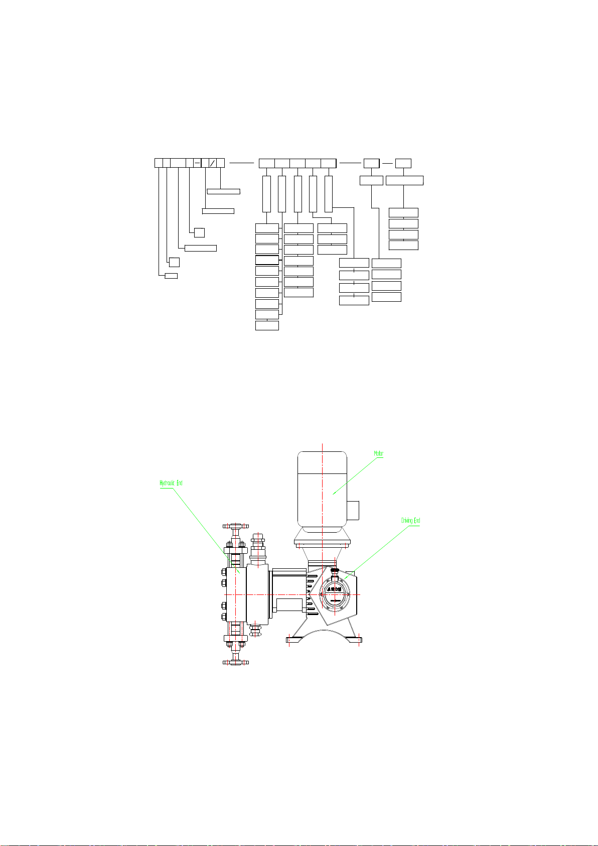
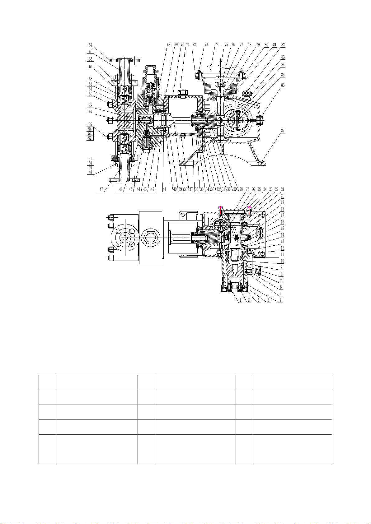
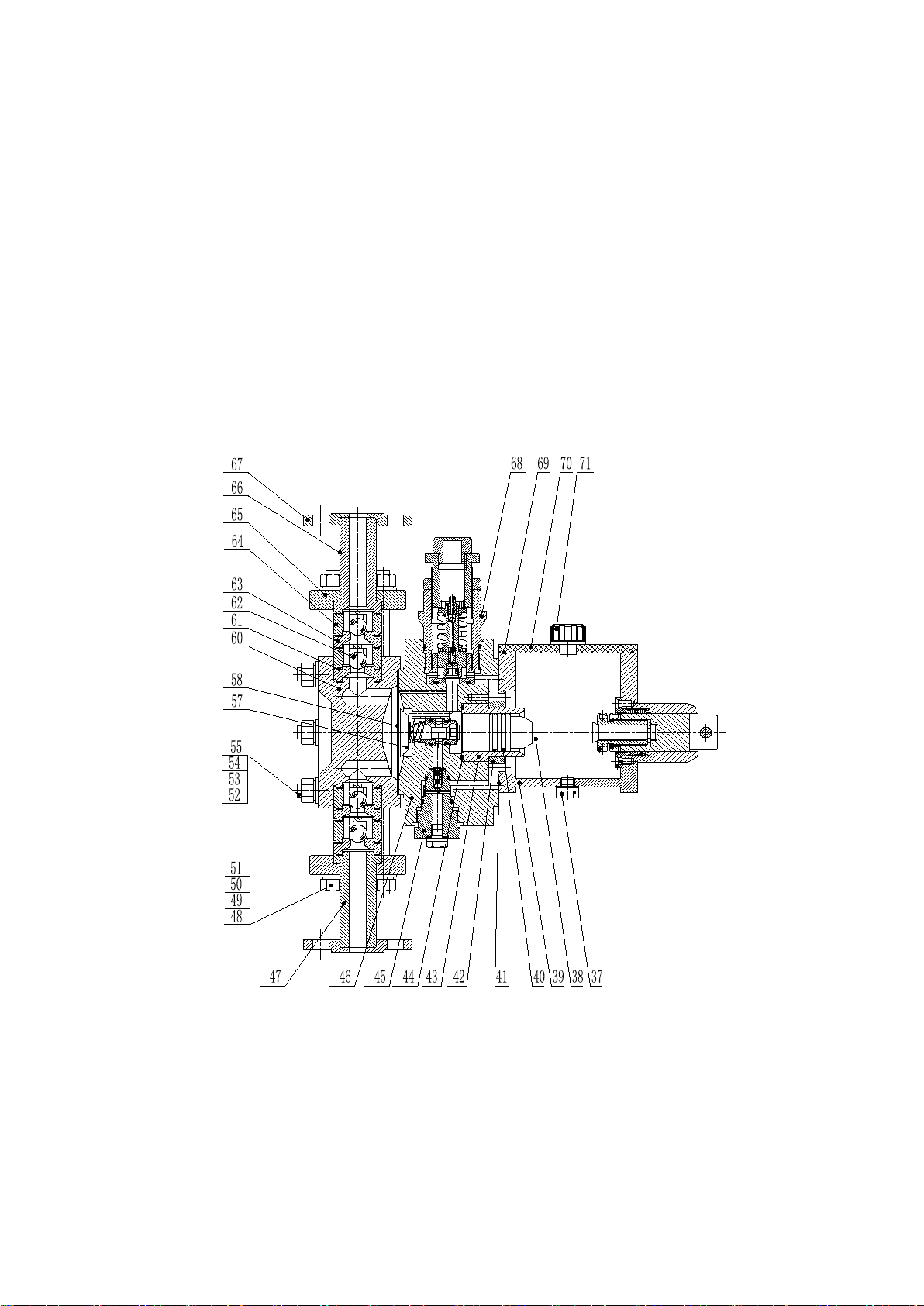
The Instructions are only applicable to JYM1.6 Hydraulic diaphragm metering pumps.

4
1.1Production Code
Stainless Steel
with Fluorine
F-
T-Cutting Sleeve
Pump Material
S
YD-Explosion Alarm
Pressure Gauge
YC-
YB-Standard Alarm
Non
N-
Diaphragm Rupture Alarm
N
Digital
K-
V-PVDF
Carbon Steel
Q-
T-PTFE
Hydraulic Didphragm Type
YM
Hydraulic Diaphragm Dosing Pump Production Code
2J
1.6
45
2.0
KHS B
Pump Head
Dosing
Pump
Series
Rated Capacity L/H
Rated Pressure Mpa
S-304
316L
L-
C-Hastelloy
20# Alloy
H-
T-Titanium Alloy
PVC
P-
H-Articulated Joint
Welded Joint
Hose
R-
F-Flange
NPT Thread
P-
M-Metric Thread
Tapered Thread
G-
Manual
S-
D-Electric
B-Explosion Proof
Variable Frequency
P-
BP-Explosion-proof with
Varibale Frequency
Standard
0-
D
Head Type
High Visicosity
N-
Temperature
Protection Jacket
T-
W-Simple Heating
D-Electric Heating
ValveMaterial
Connection Method
Control Type
Motor
II、Pump Structure and Working Principle
The metering pump generally consists of a pump motor, a driving end, and a hydraulic end (see Figure 1).
Fig.1 Metering Pump outside drawing

5
2.1 Driving End
The structure of metering pump driving end has 3 functions: First one is the retarding transmission; second one
is conversion of dynamic form; third one is the adjustment of crank radius rotation. It’s a retarding mechanism
constituted by worm and worm gears, and achieves dynamic retarding transmission. The crank-link mechanism
constituted by eccentric wheel, connecting rod and crosshead hinge completes the transition from rotation to
reciprocation. Sliding shaft, sliding shaft pin, adjusting screw rod, adjusting screw nut, scale-plate and adjusting
handle constitute
crank rotation radius adjusting mechanism. Parts of this 3 functions are bulked in the
transmission case to form driving end. The structure of driving end is shown in Figures 2.
Working principal:
The working principle of retarding transmission and power conversion is that high speed rotary motor shaft
makes use of elastic coupling to transmit torque. Then it will slow down by worm and worm wheel. Rotation of
worm wheel is to drive worm-wheel shaft. The eccentric gear and its constituted crank-link mechanism turn the
rotation movement to crosshead straight reciprocating motion.
Crank rotation radius adjusting mechanism: To adjust the hand wheel manually, then the adjusting
screw rod will be rotated into adjusting screw nut,it then drives the linear displacement of sliding
shaft (N shaft). The both ends of sliding shaft pin are installed in the
eccentric gear, a
nd the middle end
is covered inside the skewed slots of sliding axial. With the linear displacement of sliding axial, the
sliding shaft pin will drive the
eccentric gear
for linear movement. No matter the metering pump is in
downtime or revolving, it can change the radius of gyration, thus to change the stroke length of
crosshead (plunger). The pointer and scale plate move relatively. The location showing by the pointer
can display the relative stroke length % in the scale plate.

6
Figure 2 Structure Diagram of Driving End
Table 1 List of parts
No.
Name
No.
Name
No.
Name
1
Trademark
30
Retaining ring
60
cylinder head 136
2
Crossheaded screw M6x20
31
Seal ring Yx-d36
61
valve gasket F16-D
3
Hole Circlips 62
32
Bracket gasket
62
Valve ball F16-Q
4
Adjusting handwheel
33
Hexagon countersunk head
screwM6x10
63
valve seat F16-Z

7
5
Column pressure
34
Oil seal cover
64
Valve sleeve F16-T
6
O type sealing ring 9.5x1.8
35
Lock nut
65
Pressure valve flangeF16-YL
7
Stroke lock handle
36
Column nut
66
Outlet pipe F16-CG
8
Adjusting screw
37
Screw M12
67
Flange
9
Adjusting seat
38
Piston 36
68
Relief valve assemblyQAF1
10
External Circlips
39
Bracket
69
Bracket cover seal ring
11
Deep groove ball bearing 6303
40
Piston ring 36
70
Bracket cover
12
Adjusting seat gasket
41
Cylinder gasket
71
Breather plug
13
bearing cover
42
Cylinder flange
72
Motor bracket
14
Taper end set screw M4x8
43
Hydraulic cylinder 36
73
Bolt M10x30
15
Tapered roller bearing 32008x2
44
O type sealing ring 43.7x2.65
74
Motor 0.55KW
16
Slip shaft
45
Compensation valve
assembly
75
Motor coupling
17
connecting rod
46
Cylinder block 136
76
key6x6x28
18
Eccentric wheel
47
Inlet pipe F16-RG
77
Coupling elastic block
19
Worm shaft
48
Pressure valve screw
78
Worm coupling
20
Worm gear 135
49
Hexagon nut M12
79
Worm
21
key 12x8x22
50
Flat washer 12
80
Tapered roller bearing 30205
22
Worm gear seat gasket
51
Spring washer 12
81
Worm seat
23
Screw M8x16
52
Cylinder screw M12
82
Oiling window
24
Tapered roller bearing 32008x2
53
Hexagon nut M12
83
Hole Circlip10
25
Worm gear seat II
54
Flat washer 12
84
Slide pin
26
Crosshead pin
55
Spring washer 12
85
Pin sleeve
27
Hole Circlips 10
57
Limit valve assembly45x52
86
Embedded round oil mark A20
28
Tapered roller bearing 30302
58
Diaphragm 136
87
Transmission box
29
Crosshead
59

8
2.2 Hydraulic End
2.2.1 Structure
The hydraulic end of the hydraulic diaphragm metering pump comprises medium chamber, diaphragm,
hydraulic system and hydraulic oil tank, among which the medium chamber is composed of cylinder head, inlet
and outlet valves, and inlet and outlet pipes and flanges, and the hydraulic system is composed of cylinder block,
hydraulic cylinder, plunger, seal and “three-valve” system(limit-refilling valve, deflation valve and safety
valve).
The structures of hydraulic ends for the single diaphragm metering pump shows in Figure 3
Figure 3 Hydraulic end structure for single diaphragm metering pump
The structures of hydraulic ends for the double diaphragm metering pump shows in Figure 4

9
0 10
1
2
34567
8
9
Bar
Hydraulic End Structure for
Double Diaphragm Dosing Pump
0 10
1
2
34567
8
9
Bar
0
10
1
2
3
4
5
6
7
8
9
Bar
Figure 4 Hydraulic end structure for double diaphragm metering pump
2.2.2Working principal:
Diaphragm separates the medium and hydraulic oil. The piston takes use of the power of crosshead in driving
end to conduct
reciprocating motion
in hydraulic cylinder. When the piston is in suction stroke,
oil in the
hydraulic chamber enters into displacement space of the
piston
with
piston
displacement. Pressure
drops in the liquid chamber, then diaphragm makes flexure displacement with the change of
hydraulic oil. After the flexure displacement exceeds the median, it pushes the limit valve to turn on
the oil supplementary channel. When there’s 80% vacuum inside the liquid chamber, oil
supplementary valve turns on timely to automatically supplement the insufficiency. Meanwhile, with
the flexure displacement of diaphragm in medium chamber, the pressure in the chamber drops to be
different from differential pressure of the outside world. Then outside pressure presses the medium
into medium chamber.
At the moment when the piston suction stroke terminates and discharge stroke starts, the pressure in
liquid chamber surges. The deflation valve is turned on to let out gas-liquid mixture accumulated in
the top of liquid chamber, then shut down soon. The piston continues the displacement. Hydraulic oil
pushes the diaphragm, and diaphragm conducts reverse deflection displacement to expel the medium
to be discharged from outlet valve, and then flow into process pipeline. When the discharge stroke
terminates, the piston turns to suction stroke. Then, the next cycle begins. It’s to transport the
medium from a low position to a higher position.

10
Diaphragm material and Diaphragm rupture alarm device
Due to the medium which the pump conveys is flammable, explosive and corrosive, no leakage is
allowed in the field, also, it requests the diaphragm used should be featured in corrosion resistance,
strong pressure bearing capacity and long service life. So, adopt PTFE material as the diaphragm of
the pump, it is characterized as excellent aging resistance, low hygroscopicity, outstanding
self-lubricating performance, and corrosion resistance against almost all chemicals. The design also
takes advantages of double diaphragm to ensure the safety of the medium liquid during the process
of addition. Moreover, pressure sensor is design at the pump head, which can alarm the damage of
any diaphragm in two diaphragms. That’s to say, one diaphragm breaks, another diaphragm can
continue to work for a short time. When the diaphragm breaks, the design ensures that the system is
sealed, the medium liquid and hydraulic oil are not mixed together, meanwhile prevents air from
entering the system as well as the loss of the metering liquids.
Diaphragm rupture alarm device of metering pumps is mainly comprised of alert source (component
constituted by pressure ring wrapped by double diaphragm in diaphragm pump cavity), pressure
sensor (pressure signal to electrical signal ).
Working principle: Double diaphragm chamber of the alert source match each other closely after
automatic vacuum operation. It ’s same to single diaphragm, which can make reciprocated
displacement of flexure. Once any diaphragm breaks, it will destroy the vacuum in the double
diaphragm. When the piston enters into the stroke, medium liquid (transported medium or liquid oil)
will enter into the alert source. When the piston is converted to discharge stroke, the chemical will
been pushed into the pressure sensor. Pressure sensor contains pressure gauge, which indicates “0”
when the diaphragm under normal working condition, once the diaphragm is rupture, the pointer will
sway. If the warning device is local pressure gauge display, the pressure gauge will display the
process pressure, it indicates the diaphragm of the pump may break, shall shut down for check or
replacement.

11
Figure 5 Diaphragm Rupture Warning Device Schematic Diagram
2.2.3“Three valves”of hydraulic system:
The most outstanding feature of hydraulic diaphragm metering pump is the continuous process in which
diaphragm separates medium and hydraulic oil, the plunger drives hydraulic oil, the oil drives
diaphragm, and
diaphragm absorbs and discharges media. The measuring accuracy of hydraulic diaphragm metering
pump totally depends on hydraulic system, while the reliability of the hydraulic system shall be
guaranteed by 3 valves (Oil refilling valve, deflation valve and safety valve).
2.2.3.1 Limit-refilling device
The hydraulic pressure diaphragm metering pump adopts limiting-refilling system, which makes a
new leap to the technical level of hydraulic pressure diaphragm metering pump. The limit valve
restricts the position for oil filling. Once the piston passes the mid-point conductor in suctioning
stroke, diaphragm will push the limit valve to exit the oil filling passage. Then if the vacuum degree
in the liquid chamber reaches 80%, the refilling valve will refill oil to the liquid chamber
automatically to guarantee the fullness of the liquid chamber and avoid excessive oil refilling and
protect diaphragm. When there’s a negative pressure in the inlet, it also has a function of
self-absorption. It both improves volume efficiency of the pump, and measurement accuracy.
1) Limit valve
The limit valve comprises the valve sleeve and valve spool which are well matched. A limit body is arranged at
the right end of the valve spool, and a limit spring is placed between the limit body and the valve sleeve; a limit

12
retaining ring is arranged at its left, and a tool withdrawal groove is located at the center of the valve spool, then
a radial through-hole is drilled on the valve sleeve which is matched with the tool withdrawal groove. The limit
valve is developed and designed into a reasonable and ingenious structure, the radial through-hole, tool
withdrawal groove and spring are perfectly mounted, thus not only effectively controlling the diaphragm
flexural deformation of the a limit spring at the rear dead point and automatically controlling the oil make-up
quantity, but also improving the measurement accuracy of pump and the service life of diaphragm.
A. Structure (see Figure 6)
1 2 3 4 5 6 7
Serial number Code Name Quantity Material
1 GB894.1-1986 Retaining ring 14 65Mn
2GB894.1-1986 Retaining ring 22 65Mn
3GB3452.1-1982 O-ring 17x2.65
4 GB3452.1-1982 O-ring 20x2.65
5Limit valve sleeve 45
XWF-45-01
6XWF-45-02 imit valve spring 4Cr13
7XWF-45-03 Limit spool 40Cr
1
1
1
1
1
1
1
NBR
NBR
Figure 6 Structure Diagram of Limit Valve
The limit valve is mainly composed of valve sleeve, valve spool and limit spring. The complete set of limit
valve is installed at the center of the cylinder block and fixed with a circlip for shaft, and two O-rings (see the
structure diagram of pump hydraulic end) are placed on the outer ring of limit valve sleeve for connecting the
limit valve to the cylinder block seal. Furthermore, the valve spool fits valve sleeve with a clearance left so that
they can axially move under the action of spring, and a circlip for shaft is installed at the end of the valve rod for
limiting the axial movement of the valve spool. The through-hole in the middle of the valve sleeve and
corresponding small groove in the middle of the valve rod are used as oil makeup channels of the valve spool.
Common diaphragm ruptures mainly result from failure of the two O-rings on the limit valve sleeve or excessive
fit clearance between the limit valve spool and the valve sleeve, so the diagram shall be checked and controlled
during maintenance.

13
2) Oil refilling valve
A. Structure (see Figure 7)
The oil refilling valve mainly comprises pressure valve nut, seal nut, valve seat, valve spool (connecting rod
ball), spring, spring seat, filter and O-ring. The oil refilling mechanism is installed at the bottom of the cylinder
block mounting position (see the structure diagram of pump hydraulic end), and the two O-rings on the valve
must be intact for good sealing performance upon installation. The connecting rod ball shall be inserted into the
valve seat hole, and the ball and hole shall be tightly sealed. The connecting rod body is provided with a spring,
spring seat and two lock nuts, and the connecting rod ball can axially run out under force. In addition, the
cross-drilled hole on the outer ring of valve seat is used as an oil-liquid makeup channel. In order to refill clean
oil, the external ring of the valve is provided with a filter.
1
2
3
4
56
7
8
9
10
11
7
160 mesh
Filter
BYF-05
6
5
Subassembly
Connecting rod ball
BYF-04
4
45
Valve seat
BYF-03
3
45
Pressure valve nut
BYF-02
2
Q235-A
Sealing nut
BYF-01
1
GB3452.1-1982 O ring 16*1.8 NBR
GB3452.1-1982 O ring 25.8*2.65 NBR
8BYF-06 Spring 60Si2Mn
9BYF-07 Spring seat Q235-B
10 BYF-08 Gasket 1 F4
11 GB170-1986 Nut 2
Serial number Code Name Quantity Material
1
1
1
1
1
1
1
1
1
Figure 7 Structure Diagram of Oil refilling Valve
B. Reasons
The oil refilling valve acts mainly because the diaphragm chamber is not full after leakage occurs. Specifically,
when the piston is pushed in, the diaphragm chamber is empty. If the piston is further pushed in, a vacuum is
formed inside the diagram chamber. Under certain vacuum conditions, the oil refilling valve spool (connecting
rod ball) will make up oil against spring so that the diaphragm chamber is full of hydraulic oil, the diaphragm
withholds equal force on both sides, and its service life is prolonged.
C. Adjustment
For the oil refilling valve, its spring force is mainly adjusted. Under common working conditions (when the inlet
is under positive pressure), the spring force of connecting rod ball should be adjusted at around 100g (f). If the
pump is pushed in, especially under certain negative pressure, the spring force will gradually increase, so as to
avoid diaphragm damage resulting from excessive oil refill.

14
3) Deflation safety valve
A. Structure (see Figure 8)
17 16
15
14
13
12
11
10
9
6
5
4
3
2
1
7
8
13
14
15
16
12
11
10
17
J5AQF-13
GB3452.1-82
J5AQF-12
J5AQF-11
GB308-84
J5AQF-01
GB3452.1-82
GB893.1-86
O ring
Valve ball
spring
Valve spring
Valve core
O ring
Gasket
Rtainer ring
4
8
7
6
5
9
J5AQF-04
J5AQF-06
J5AQF-05
J5AQF-07
J5AQF-09
J5AQF-10
Guide rod
Valve casing
Lock nut
Adjusting screw nut
Windows
Spring seat
1
1
1
1
1
1
1
1
1
1
1
1
2
1
45
45
35
35
45
Organic glass
陶瓷ceramic
65Mn
Oil resistant
rubber
40Cr
65Mn
35
65Mn
Quantity
Name Material
1
1
1
40Cr
40Cr
40Cr
code name
numerical
order
J5AQF-02
J5AQF-03
2
3Spherical pad
Valve core
1J5AQF-01 Valve seat
Oil resistant
rubber
Figure 8 Structure of deflation safety valve
The valve body and valve seat in deflation safety valve are connected by threads. The bottom surface of the
valve seat cavity and the end face of the valve core need to be grinded to improve the sealing accuracy. The
safety valve core is equipped with an deflation safety valve core, which also needs to be grinded to obtain
reliable sealing. The top of the safety valve core is installed with an air valve spring. The safety valve core is
loaded with spring seat and valve spring, and the outlet passage of the valve core is equipped with non-return
valve ball SØ5 and adjusting screw. The valve body is equipped with adjusting nut and locking nut to adjust the
spring force. When the system pressure exceeds the spring compression force of the safety valve core, the safety
valve core is opened, the hydraulic oil spills back to the oil tank, and the system relieves pressure, which can
protect the pipeline system and the pump.
The designed deflation safety valve is installed on the top of liquid chamber to discharge the gas of hydraulic oil
in liquid chamber, then the liquid chamber can keep to be in pure liquid when driving the diaphragm. Thus it can
improve both volume efficiency of the pump and measurement accuracy. Meanwhile, it avoids self-discharge
function which appear when the discharge pipe is over pressure.
The valve structure is in smart design, simple structure, and combines safety valve and deflation valve into one
unit. It greatly simplifies the structure of hydraulic pressure
diaphragm metering pump, shrunk the volume,
reduces the production cost and improves the control performance of safety valve.

15
B. Functional structure
The deflation device mainly comprising deflation valve spool, deflation valve spring, valve ball, clearance
adjustment pad and retaining ring is installed in the safety valve spool. Oil pressure fluctuates as the piston
moves back and forth during operation. When the piston is pushed in, the deflation valve spool is jacked by
spring; when the piston is pushed out, gas will flow out of the oil chamber through the clearance of valve spool
due to instantaneous pressure increase in the diaphragm chamber after the valve ball is jacked. The deflation
valve spool will compress the valve spring and stop gas exhaust. The opening height of valve spool is adjusted
according to the washer thickness, and the flow is generally in direct proportion to the opening height. For
example, when the system pressure is high, the opening height of valve spool can be appropriately reduced. For
low flow pumps, the opening height of valve spool may be controlled within 0.05~01mm. But for large flow
pumps, that shall be controlled within 0.2~0.5mm.
C. Adjustment
The opening pressure of deflation safety valve has been set as required when it leaves the factory, and if the
actual exhaust pressure is different from the rated exhaust pressure, it shall be adjusted according to the table
below.
Rated exhaust pressure of pump, Pdr (MPa)
0.2~1.2
1.2~4.5
4.5~9.0
9~20.0
Opening pressure of hydraulic safety valve, Pk(MPa)
Pdr+0.3
1.3Pdr
1.2Pdr
1.15Pdr
Early opening or opening failure of the safety valve when the working pressure of pump is lower/higher than the
opening pressure given in the table is abnormal; if any, the compression force of safety valve spring shall be
adjusted or even the safety valve shall be disassembled for cleaning, so as to ensure the normal operation of
exhaust safety valve and maintain the stability of flow.
Attention: The deflation safety valve of the pump is used to ensure the safety of the oil cylinder of the pump,
especially for high flow pumps, and shall not be mounted on the process line.
2.3 Pump flow regulation
The adjusting handwheel is rotated to drive the adjusting screw for axial movement of the adjusting nut which is
engaged with it; as the pointer installed on the adjusting nut is connected with the guide and the E-type slide
shaft is connected with the guide through the bearing, the E-type slide shaft will axially move as the adjusting
handwheel rotates, and the eccentricity of the eccentric gear will change under the action of the slide shaft chute,;
namely, the turning radius of the eccentric gear will change for the purpose of changing the reciprocating

16
displacement of the crosshead and adjusting the flow. If the eccentricity between the E-type slide shaft and the
center of the eccentric gear reaches half of the maximum stroke, the pump will reach the maximum stock (i.e.,
100% of the relative stroke) and the maximum discharge flow. As the E-type slide shaft axially moves, the
center of eccentric gear will get closer to the center of the slide shaft; where both centers are overlapped, the
eccentricity of the eccentric gear will be zero, and it will be deemed as the zero point where the pump does not
discharge fluid and the pointer of the pump adjusting mechanism points at zero.
The pump stroke can be adjusted during shutdown or operation, and it will take about 1~2min to keep the pump
flow stable after adjustment. In particular, the greater the stroke change, the longer the time for keeping the flow
stable, especially for diaphragm pumps.
Each metering pump has received normal-temperature water test before leaving the factory, and is attached with
a test report. The users must retest the metering pump and recalibrate the flow curve according to the actual
working conditions , so as to regulate the flow according to such flow curve during operation.
III、Installation
1. The pump shall be installed on a special spare concrete foundation or cast iron platform and fixed with
foundation bolts after re-calibration, and the concrete foundation shall be 50~100mm above the ground to
prevent being washed by water. At the same time, it needs to reserve enough space around the pump to
facilitate the maintenance and adjustment of the pump.
2. The diameters of the suction and discharge pipe should not be less than the diameter of the inlet and outlet
pipe of the pump, and the suction pipe should be as short as possible. If the inlet pipe of the metering pump
is too long or the viscosity of the medium is larger, the diameter of the inlet pipe should be increased,
otherwise it will affect the normal operation of the pump.
3. The connecting pipe shall be equipped with measuring instruments, such as pressure gauges.
4. Filter devices shall be installed at the end of the suction pipe.
5. The discharge pipe shall be fitted with a safety valve or a safety-relief valve (provided by the user). If you
need to reduce the pressure fluctuation at the outlet, please install a pressure stabilizer (such as a buffer)
near the discharge pipe. Safety valve and buffer tank of the pipe are important accessories of the metering
pump. The pipe safety valve is usually installed in the discharge pipe behind the centralized liquid pipe,

17
which has the function to prevent the pressure of the outlet pipe being too high, so as to protect the safe
operation of the pump. The buffer tank is used to reduce the non-uniformity of the flow in the pipe and then
to reduce the flow fluctuation. It is an auxiliary equipment for the purpose of reducing the non-uniformity
of the flow in the pipe by using the compression and expansion of the gas to store or release a part of the
liquid.
6. Pumps installed outdoor should be sheltered by rain cover.
7. When the pressure of the outlet pipe is less than 0.3MPaG or the inlet pressure is greater than the outlet
pressure (there is artesian phenomenon), the counterbalance valve should be installed at the outlet pipe of
the metering pump to ensure the accuracy of the fluid dosing of the metering pump.
IV、User Guide
4.1 Preparation
1) Before pump operation, check whether the bolts and nuts at the connections are loose; if a new pump is
used, scrub anti-corrosive grease or dirt with kerosene, and do not scrape off it with a knife by force.
2) L-CKE200# worm and worm gear oil (SH/T0094-1991) or N220 gear oil is filled into the transmission box
in priority, and oil shall be filled to the horizontal centerline of the oil level sight glass. 25# transformer oil
is filled into the hydraulic oil tank at 30~50mm below the opening of the bracket body, and the oil level is
generally not below the centerline of the plunger. The hydraulic tank is usually filled with appropriate
amount of transformer oil when leaving the factory. However, the users shall fill lubricating oil into the
transmission box by themselves.
The oil capacity of the transmission box and hydraulic tank of JYM25 (JYMT) single-cylinder hydraulic
diaphragm metering pump: 32L for transmission box and 15L for hydraulic box.
3) Manually rotate the motor fan to move the plunger in full stroke without jamming. Turn on the power, start
the motor, check whether the rotation direction of the motor and the rotation direction of the pump is
consistent. The inlet and outlet valves on the pipes shall be fully open.

18
4.2 Flow Adjustment (See above 2.3 Flow Adjustment)
4.3 Operation
Upon completion of the above preparatory work and confirmation, start the motor and put it into operation. The
operation process should be stable, and there should be no abnormal noise, otherwise please shut down the pump to
check. After finding the source of noise, please put it into operation again.
4.4 Flow Calibration
Pump flow calibration test should be carried out in the initial pump operation, so as to confirm the exact flow
under specific operating conditions. The stroke is usually set when the flow is 100%, 75%, 50%, 30%, 10%
respectively. By calibrating the pump flow, it is sufficient to indicate the performance of the pump in the whole
regulating range.
4.5 Shut Down the Pump
The outlet valve should be in the full open state to reduce the discharge pressure of the pipe to normal pressure,
and then cut off the power supply to stop the motor operation.
4.6 Oil filling into diaphragm chamber of hydraulic diaphragm metering
pump
When the pump leaves the factory, the pump diaphragm chamber is full of transformer oil, so the users do not
need to disassemble it for refilling. In the following circumstances, it is necessary to fill oil into the diaphragm
chamber:
1) Hydraulic oil leaks from the diaphragm chamber at the cylinder block side after disassembly of the oil
makeup valve for cleaning;
2) Hydraulic oil leaks from the diaphragm chamber at the cylinder block side after disassembly of cylinder
head (pump head) and replacement of the diaphragm.
3) Oil filling into the diaphragm chamber: to empty the gas from the diagram chamber in the shortest time,
shorten the commissioning time, and put the hydraulic system into normal operation quickly.
Table of contents
Other Zhejiang Water Pump manuals
Popular Water Pump manuals by other brands

ITT
ITT GOULDS PUMPS 3198 Installation, operation and maintenance manual

Rietschle
Rietschle COVAC SMV 160 operating instructions

Hoval
Hoval HSP 15/6 Installation and operating instructions

national-spencer
national-spencer 7019 Instructions and precautions

INOXPA
INOXPA PROLAC HCP Ex Installation, service and maintenance instructions

XPOtool
XPOtool 62543 Operation manual

Half Off Ponds
Half Off Ponds Piranha Series Operation manual

Graco
Graco Fire-Ball 300 Instructions and parts list

Bauer
Bauer Magnum S operating manual

Crane
Crane BARNES 3SHVRA150N2 Installation and operation manual

Ebsray
Ebsray R SERIES Installation, operation & maintenance instructions

K&T
K&T 3.532-757.0 Service handbook