Ziegler RA10 User manual

User's Manual
www.ziegler-instruments.com 1|29
© Ziegler Instruments Order No. User Manual-E1.R0-921022-2-2014-ENRA 10
RA10
Digital Multimeters
Analogue Meters With Moving - Iron Movement

1000 V
fused
OFF WF
Hz/%
V~
0C
F
0C
OFF
W
A
mA
FUNC AUTO/MAN REL HOLD/ON
0
C
V~
V
A~
mA~
RA 10
www.ziegler-instruments.com 2|29

www.ziegler-instruments.com 3|29
RA 10 Operating Elements
1 Terminal Sockets
2 LCD Display
3 Data HOLD/ ON Pushbutton
4 Pushbutton for Relative value
5 Function Selector Switch for ON/OFF
and Measurement Function Selection
6 Pushbutton for Automatic or Manual
range selection
7 Multifunction Pushbutton ( yellow key)
Display
1 Digital Display with Indication of Decimal Point and
Polarity
2 Low Battery Display
3 REL, HOLD, Display
4 Continuity Test Display : Buzzer Indication
5 Diode Measurement Display
6 Display for Unit of Measured Quantity
7 Display for Automatic Measuring Range Selection
8 Display of Selected Current / voltage Type

1. Safety Features and Precautions ...................
2. Initial Start-up ...................................................
3. Selecting Measuring Functions & Ranges ....
3.1 Measuring Function Selection............................
3.2 Automatic Measuring Range Selection..............
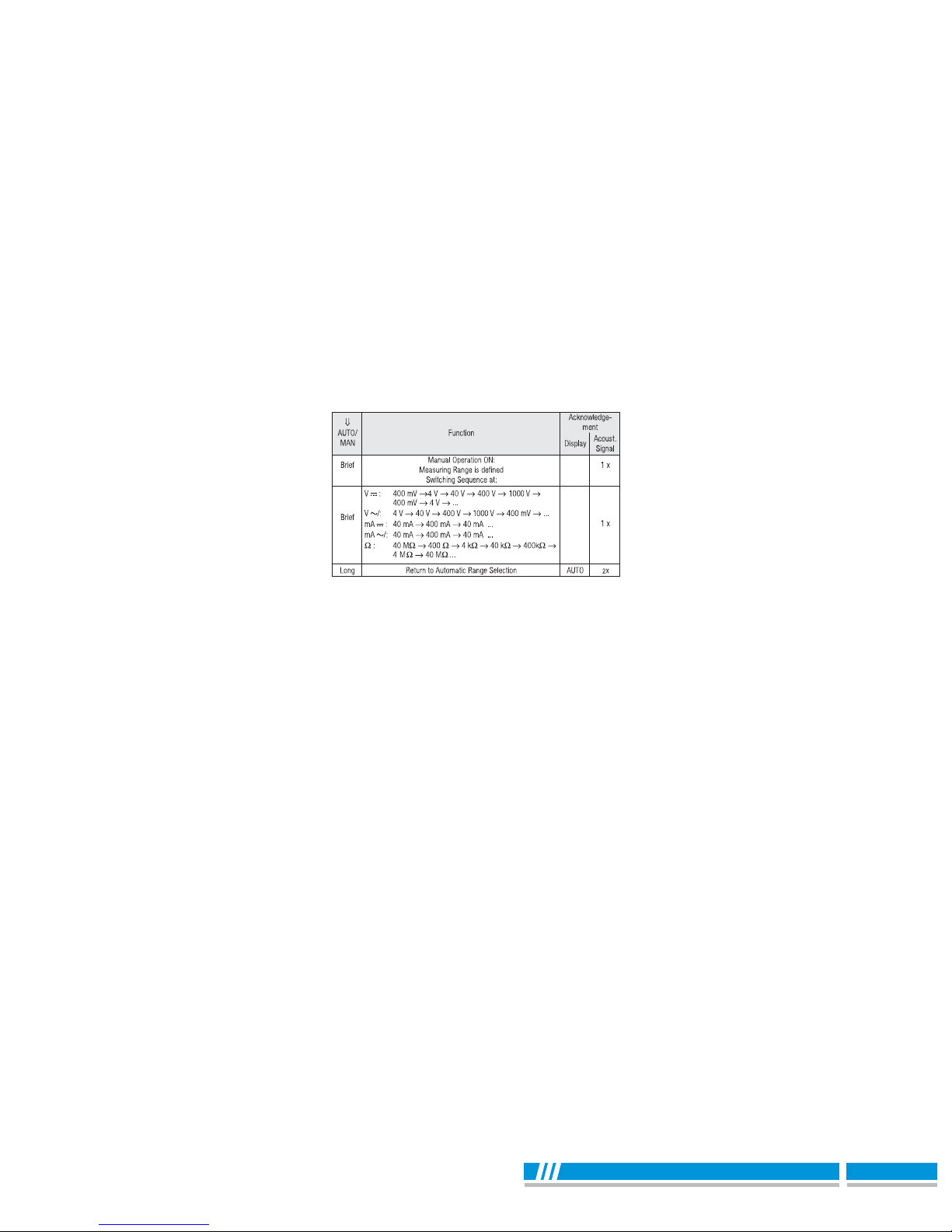
3.3 Manual Measuring Range Selection..................
4. Liquid Crystal Display ....................................
4.1 Digital Display ...................................................
5. Buzzer ..............................................................
6. Measurement Value Storage “HOLD”............
7. REL - Relative value measurement ...............
8. Voltage Measurement .....................................
9. Current Measurement ....................................
9.1 AC Measurement with (Clip-on) C.T. ................
10. Diode Testing & Continuity Measurement ....
10.1 Diode Testing ....................................................
10.2 Continuity Testing .............................................
11. Resistance Measurement ...............................
12. Capacitance Measurement ............................
13. Frequency & Duty cycle Measurement ........
13.1 Frequency Measurement .................................
13.2 Duty Cycle Measurement .................................
14. Temperature Measurement ............................
15. Specifications .................................................
16. Maintenance ....................................................
16.1 Battery ..............................................................
16.2 Fuses ................................................................
16.3 Housing .............................................................
17. Repair and Replacement parts service .........
5
7
8
8
9
9
10
10
11
11
11
11
13
14
15
15
16
17
18
20
20
20
21
22
27
27
28
29
29
www.ziegler-instruments.com 4|29

You have selected an instrument which provides you with a
high level of safety.
The RA 10 digital multimeter is manufactured
in complaince with safety regulations. In case of incorrect
use or careless handling, the safety of both user and
multimeter is not assured.
To maintain the safe and proper condition of the meters
and to ensure their safe operation, it is absolutely neces-
sary to carefully and completely read these operating
instructions before using any meter. These instructions
must be followed in all respects.
Observe the following safety precautions :
* The meter must only be operated by persons who under-
stand the danger of shock hazards and know how to apply
safety precautions. Shock hazards exist anywhere, where
voltages of more than 30 V (TRMS) may occur.
* Do not work alone in shock hazardous environment while
carrying out measurement
* The maximum allowable voltage between any terminal
sockets (1) and earth is equal to 1000 V. Voltages of
greater than 500 V may only be applied to sockets " ", and
"V" with the selector switch in the voltage measurement
position (selector switch in "V" position).
* Take in to account that unexpected voltages can occur at
devices under test (e.g. defective devices). For example,
capacitors can be dangerously charged.
1 Safety Features and Precautions
www.ziegler-instruments.com 5|29

* Verify that the test leads are in good condition, e.g. no
cracked insulation, no open circuits in the leads or
connectors.
* This meter must not be used for measurements on circuits
with corona discharge (high-voltage).
* Be particularly careful when measurements are made in HF
electrical circuits. Dangerous composite voltages may be
present.
* Measurements under moist ambient conditions are not
permitted.
* Do not exceed the permissible overload limits of the
measuring ranges. Limit values can be found in the table
"Measuring Ranges" in chapter 15 "Specifications".
* All current ranges are equipped with fuses. The maximum
allowable voltage for the measuring current circuit
(=nominal voltage of the fuse) is equal to 600 V~.
* The instrument may only be used in power installations
when the electrical circuit is protected with a 20 A fuse
or circuit breaker, and the nominal voltage of the installation
does not exceed 1000V.
www.ziegler-instruments.com 6| 29

Repair, Parts Replacement and Calibration
After opening the meter, live parts may be exposed. There-
fore, the meter must be disconnected from the measuring
circuit prior to opening its case for repair, replacement of parts
of calibration. If repair or calibration cannot be avoided unless
the meter is open and live, this work must be performed by a
qualified person who understands the danger involved.
Faults and extraordinary Stress
When it must be assumed that the safe operation is no longer
possible, take the meter out of service and secure it against
accidential use.
It is assumed that Safe operation is no longer possible,
* when the meter shows oblivious sign of damage,
* when the meter no longer functions correctly,
* after a prolonged storage under adverse conditions,
* due to severe stress due to transportation.
2 Initial Start-Up
Battery
Fit the meter with battery (batteries) provided along with the
meter
please see chapter 16.1, page 27, before initial start-up of
your instrument, or after a lengthy period of storage.
Switching the Meter ON
Turn the Function selector switch from the OFF position to the
desired measuring function.
All of the segments of LCD are activated briefly.
A drawing of the LCD can be found on page 2.
www.ziegler-instruments.com 7|29

Automatic turn-OFF
Your meter switches itself OFF automatically after
15 minutes, if no keys or the selector switch have been
activated during this time.
Switching the Meter back ON
Activate the HOLD/ON key.
Switching the Meter OFF
Turn the selector switch to the OFF position.
3 Selecting Measuring Functions and Ranges
3.1 Measuring Function Selection
The desired measuring function is selected with the Function
selector switch (blue or yellow printing). In order to select the
function printed in yellow half circle, the yellow multifunction
key must also be pressed. If the multifunction key is pressed
again, the function printed in blue half circle is reactivated.
Note !
Electrical discharge and high frequency interference
can cause incorrect displays, and may block
the measuring sequence. To reset, switch the
meter off, and then back on. If this procedure is
unsuccessful, briefly disconnect the battery from
the contact terminals.
Attention !
Before opening, disconnect the meter from the
measuring circuit and observe chapter 16,
page 27!
www.ziegler-instruments.com 8|29

AC
3.2 Automatic Measuring Range Selection
These multimeters features autoranging for all measuring
ranges except for the ranges 400 mV ~ and 10 A. Automatic
selection is functional as soon as the meter is switched ON.
According to the measured quantity applied, the meter auto-
matically selects the measuring range which gives the best
resolution.
3.3 Manual Measuring Range Selection
You can switch OFF autoranging, select and fix the ranges
manually according to the table given on page no. 10.
First select the desired measuring function with the
function selector switch and, if appropriate, the
multifunction key.
Briefly activate the AUTO/MAN key.
Manual mode is switched OFF if you press and hold the
AUTO/MAN key until you hear a second acoustic signal,
and the display switches to AUTO.
When switching back to automatic operation in the
400 mV~ range occurs, the 4 V ~ range is activated.
www.ziegler-instruments.com 9|29

Note : 0
For Temperature (C), Frequency (Hz), Duty cycle (%)
and Capacitance (F) measuring range is always Auto.
No manual range selection is possible.
4 Liquid Crystal Display
4.1 Digital Display
The digital display shows the measurement value, decimal
point and sign. The selected measuring unit and function are
displayed. When measuring DC quantities minus sign
appears in front of the digits, if the positive pole of the
measurement magnitude is applied to the " " input.
"OL" appears if the measuring range upper limit is
exceeded.
The digital display is updated thrice per second for V, A, W,
Capacitance, Frequency & Duty cycle measurements.
www.ziegler-instruments.com 10 | 29

5 Buzzer
The following steps are acknowledged by an sound signal :
* New measurement function selection
* Activation or deactivation of the following functions :
AUTO/MAN, REL or HOLD
*
When measuring AC Voltage > 750 V, DC Voltage > 1000 V,
AC/DC mA > 400.0 mA, AC/DC A > 10 A, the buzzer will
keep sounding as the overload warning.
* Approximate 1 minute before the meter is auto power off,
the buzzer will raise constantly 5 sounds to warning.
Before the meter is power off, the buzzer will raise one long
sound to warn the user.
6 Measurement Value Storage "HOLD"
By pressing the HOLD/ON key, the currently displayed mea-
surement value can be "held", and "HOLD" is simultaneously
displayed on the LCD.
The Hold display is switched OFF if :
* the Hold key is reactivated
* the function selector switch is operated
* the yellow multi function key is activated for a change of
function, e.g. AC ----> DC.
* REK key is activated.
*
AUTO/MAN key is activated
7 REL - Relative value measurement
REL key is the key to measure relative value & it acts in
activation. All functions can be used for Relative value
Measurement except Hz / duty, diode & continuity function.
8 Voltage Measurement
By pressing the HOLD/ON key, the currentl
www.ziegler-instruments.com 11 | 29

0
C
Make certain that the current ranges ("mA" or "A")
are deactivated and that the measurement cables
are connected to the correct terminals, "V and ",
before connecting your multimeter for the measure-
ment of voltage! If the fuse tripping limit values are
exceeded due to operator error, both the operator
and the instrument are in danger! Observe the volt-
are limit values as printed on the meter !
Connect the measurement cable as shown. Terminal " "
should be grounded, and the second measuring cable with
a higher potential connected to Terminal "V".
The measuring range 400 mV ~ can only be
selected manually with the "AUTO/MAN" key!
Select the respective voltage type which corresponds to the
measuring value by briefly pressing the yellow multifunction
key. Each activation of the key causes alternate switching
between AC and DC, as well as acknowledgment by means
of an sound signal. The symbols DC and ~ AC indicate the
selected voltage type in the LCD display.
After selection of this function with the selector switch,
the voltage type DC is always activated.
www.ziegler-instruments.com 12 | 29

a) Select function A with the function selector switch for cur-
rents > 400 mA, or function mA for currents < 400mA. When
measuring currents of an unknown magnitude, select the
highest measuring range first.
b) Select the function corresponding to the measured quantity
by briefly pressing the yellow multi-function key. Each time the
key is pressed, alternate switching takes place between AC
and DC, and change over is acknowledge by sound signal.
The symbols DC and ~ AC indicate the selected current
type in the LCD display.
After selection of this function with the selector switch,
the Current type DC is always activated.
c) Connect the measuring instrument in series to the load as
shown (without contact resistance).
Notes on Current Measurement :
* The meter must be used only in power systems, when the
current circuit is protected with a 20 A fuse or circuit
breaker, and the nominal voltage of the system does not
exceed 600 V.
* Make the measuring circuit connections mechanically
strong and secure, so that they do not accidently open. The
conductor cross sections and connection points should be
designed to avoid excessive heating.
* Current ranges up to 400 mA are protected with a FF1.6 A/
600 V fuse.
First switch off the power supply to the measuring
circuit and/or to the load, and discharge any capac-
itors which might be present.
www.ziegler-instruments.com 13 | 29

0
C
* In the 400 mA measuring range an intermittent sound signal
warns you, if the measurement values has exceeded the
measuring range upper limit value.
* The 10 A current measuring range is protected with a 16 A/
600 V fuse.
* If a fuse blows, eliminate the cause of the overload before
placing the meter back into operation!
* Fuse replacement is described in chapter 16.2, page 28.
If current transformers are operated with an open
circuit on the secondary side, e.g. due to defective
or disconnected leads, a blown fuse in the meter or
a wrong connection, dangerously high voltages can
occur at the connections. For this reason, verify
that the current circuit of the multimeter and sec-
ondary winding of transformer connected to the
multimeter form an intact circuit. Connect the trans-
former to the sockets and mA or A
www.ziegler-instruments.com 14 | 29

10 Diode Testing & Continuity Measurement
10.1 Diode Testing
0
C
Some currents transformers include safety devices, which pre-
vent dangerous voltage increases at open electrical circuits.
The maximum allowable operating voltage at the primary con-
ductor is equal to the nominal voltage of the current trans-
former. When reading the measurement value, consider the
transformation ration of the transformer, as well as additional
display error.
9.1.2 Transformer Output mV/A.
Some transformers have a voltage output(designation: mV/A).
Consequently, the secondary connection must be connected
to and V.
* Set the function selector switch to " ".
*Connect the device under test as shown.
Verify that the device under test is electrically dead.
External voltages would falsity the mesurement
results!
www.ziegler-instruments.com 15 | 29

10.2 Continuity Testing
0C
Conducting Direction and Short-Circuit
The measuring instrument displays the forward voltage in
volts. As long as the voltage drop does not exceed the maxi-
mum display value of 1,000 V, you can test several elements
connected in series.
Reverse Direction or Interruption
The measuring instrument displays a voltage of 'OL'
Resistors and semiconductor paths in parallel to
the diode distort the measurement results!
Verify that the device under test is electrically dead.
External voltages would falsify the measurement
results!
* Set the selector switch to " "
Press the yellow multifunction key to switch to the continuity
measuring range. Display of the symbol is activated.
The instrument generates a continuous sound signal at a
measured resistance of 0... approx. < 75 .W
www.ziegler-instruments.com 16 | 29

* Connect the Device Under Test as shown.
Verify that the device under test is electrically dead.
External voltages would falsify the measurement
results!
* Set the selector switch to " ".W
* Connect the Device Under Test as shown.
Zero Adjustment (Relative mode)
In the measurement of resistance the inherent error of the
meter and the resistance of leads can be eliminated by zero
adjustment.
- Short the leads connected to meter
- Press REL key
The instrument acknowledges zero adjustment with a sound
signal & value close to 00 & REL are displayed on LCD.
11 Resistance Measurement
0
C
0
C
www.ziegler-instruments.com 17 | 29

Set the function selector switch to "F"
Connect the (discharged!) device under test socket " " and
"F" with measurement leads. Polarized capacitors must be
connected to the " " socket at the " -- " pole.
electrically dead. External voltages would falsify the
measurement results!
The resistance measured at the moment the REL key is
pressed serves as a reference value. This value is then
automatically subtracted from all measured value.
Deleting Zero Adjustment
Short the leads connected to meter and then press REL key.
or Activate the function selector switch.
or Switch the Multimeter off.
0C
Resistors and semiconductor paths in parallel to
the capacitor falsify the measurement results!
To measure small value capacitors please use
short measurement cables!
If is displayed the measured values are not valid.
Be absolutely certain that the device under test is
www.ziegler-instruments.com 18 | 29

Zero Adjustment (relative mode)
For the measurement of small capacitance values in the 5 nF
and 50 nF ranges, the inherent error of the meter and the
capacitance of the leads can be eliminated by zero adjust-
ment.
- Connect the leads to the meter without without Device under test
- Briefly Press the REL key.
The instrument acknowledges zero adjustment with an
sound signal, and a value close to "00.00" and REL are dis-
played at the LCD. The capacitance measured at the
moment the key is activated serves as a reference value.
This value is then automatically subtracted from all mea-
sured values.
Deleting Zero adjustment
Press REL key
clearance is acknowledged by buzzer sound.
or Activate the function selector switch
or Switch the multimeter off.
www.ziegler-instruments.com 19 | 29

Duty cycle (%) = pulse duration
cycle duration X 100
13 Frequency & Duty Cycle Measurement
13.1 Frequency Measurement
a)
Set the function selector switch to V~/Hz/% and press Yellow
multi-function key, as shown on page 21.
The frequency measurement mode is activated. "Hz" symbol
is displayed on the LCD. The digital display is expanded to
9999 digits. Only the auto mode is possible, no manual range
is possible.
b) Connections are made the same way as for voltage
measurement.
c) The lowest measurable frequencies and the maximum
allowable voltages can be found in the chapter 15.
"Specifications".
13.2 Duty Cycle Measurement
a) With duty cycle measurement, we can determine the ratio
of pulse duration to cycle time of recurring square wave
signals. The duty cycle that is the percentage pulse duration
of signal is displayed on LCD i.e.
Note : The applied frequency must remain constant during
the duty cycle measurement.
b) Set the function selector switch to V~/Hz/% and press
yellow multi-function key twice as shown on page 21.
The duty cycle (%) mode is activated. "%" symbol is
displayed on LCD.
www.ziegler-instruments.com 20 | 29
Table of contents
Other Ziegler Multimeter manuals