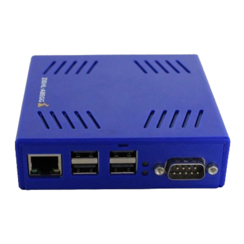
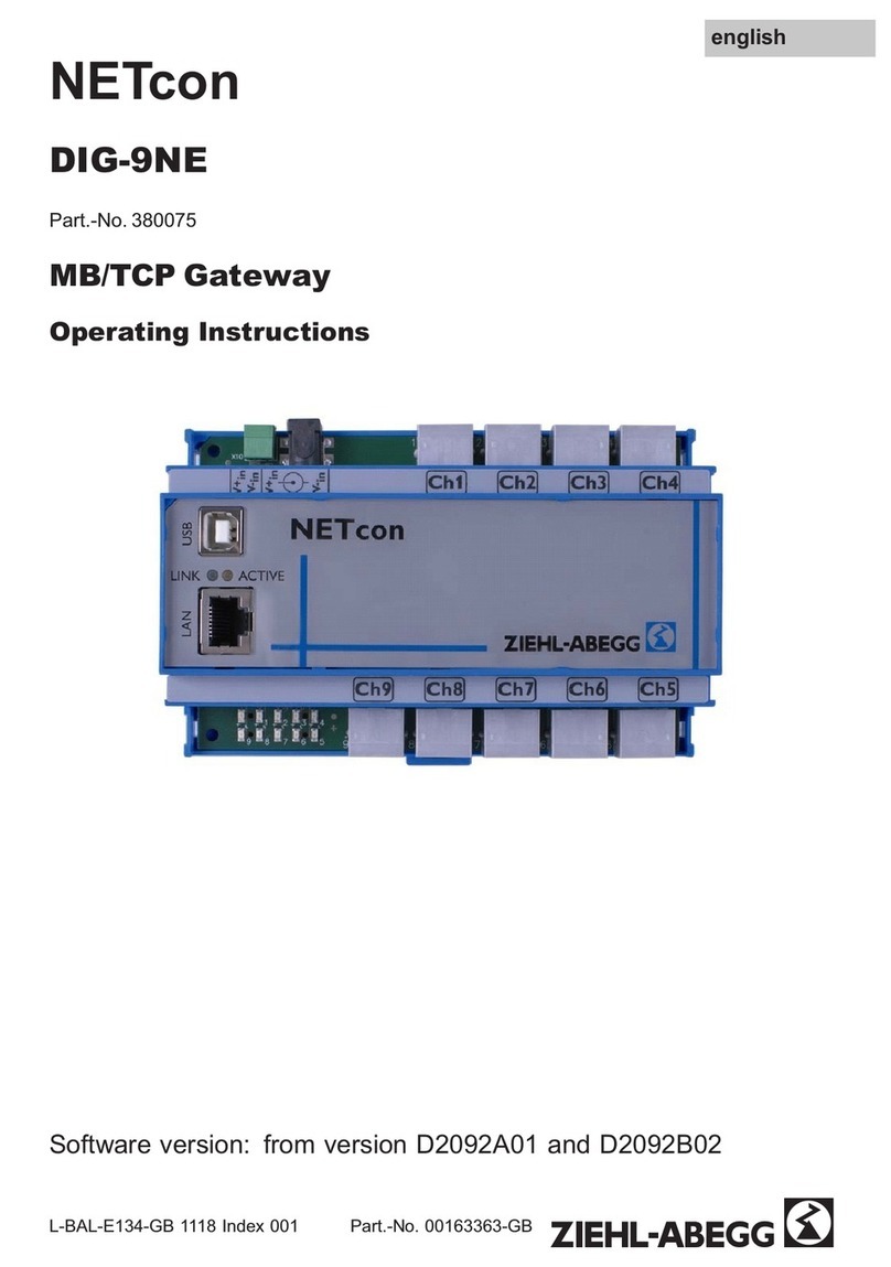
ZIEHL-ABEGG NETcon D-G-64NE User manual

NETcon
D-G-64NE
Part.-No.: 380102
Gateway PROFINET-MODBUS
Operating Instructions
L-BAL-E273-GB 1631 Index 001 Part.-No.
english

Content
1 General notes . . . . . . . . . . . . . . . . . . . . . . . . . . . . . . . . . . . . . . . . . . . . 4
1.1 Structure of the operating instructions . . . . . . . . . . . . . . . . . . . . 4
1.2 Target group . . . . . . . . . . . . . . . . . . . . . . . . . . . . . . . . . . . . . . . . 4
1.3 Exclusion of liability . . . . . . . . . . . . . . . . . . . . . . . . . . . . . . . . . . 4
1.4 Copyright . . . . . . . . . . . . . . . . . . . . . . . . . . . . . . . . . . . . . . . . . . 4
2 Safety instructions . . . . . . . . . . . . . . . . . . . . . . . . . . . . . . . . . . . . . . . . 4
2.1 Intended use . . . . . . . . . . . . . . . . . . . . . . . . . . . . . . . . . . . . . . . 5
2.2 Explanations of symbols . . . . . . . . . . . . . . . . . . . . . . . . . . . . . . . 5
2.3 Product safety . . . . . . . . . . . . . . . . . . . . . . . . . . . . . . . . . . . . . . 5
2.4 Requirements placed on the personnel / due diligence . . . . . . . 5
2.5 Start-up and during operation . . . . . . . . . . . . . . . . . . . . . . . . . . . 6
2.6 Work on the device . . . . . . . . . . . . . . . . . . . . . . . . . . . . . . . . . . 6
2.7 Modifications / interventions in the device . . . . . . . . . . . . . . . . . 6
2.8 Operator’s obligation of diligence . . . . . . . . . . . . . . . . . . . . . . . . 7
2.9 Employment of external personnel . . . . . . . . . . . . . . . . . . . . . . . 7
3 Product overview . . . . . . . . . . . . . . . . . . . . . . . . . . . . . . . . . . . . . . . . . 7
3.1 Application . . . . . . . . . . . . . . . . . . . . . . . . . . . . . . . . . . . . . . . . . 7
3.2 Function . . . . . . . . . . . . . . . . . . . . . . . . . . . . . . . . . . . . . . . . . . . 7
3.3 Maintenance . . . . . . . . . . . . . . . . . . . . . . . . . . . . . . . . . . . . . . . . 8
3.4 Transport . . . . . . . . . . . . . . . . . . . . . . . . . . . . . . . . . . . . . . . . . . 8
3.5 Storage . . . . . . . . . . . . . . . . . . . . . . . . . . . . . . . . . . . . . . . . . . . . 8
3.6 Disposal / recycling . . . . . . . . . . . . . . . . . . . . . . . . . . . . . . . . . . 8
4 Mounting . . . . . . . . . . . . . . . . . . . . . . . . . . . . . . . . . . . . . . . . . . . . . . . . 8
4.1 General notes . . . . . . . . . . . . . . . . . . . . . . . . . . . . . . . . . . . . . . . 8
4.2 Temperature influences during commissioning . . . . . . . . . . . . . . 9
5 Electrical installation . . . . . . . . . . . . . . . . . . . . . . . . . . . . . . . . . . . . . . 9
5.1 Safety precautions . . . . . . . . . . . . . . . . . . . . . . . . . . . . . . . . . . . 9
5.2 Voltage supply . . . . . . . . . . . . . . . . . . . . . . . . . . . . . . . . . . . . . . 10
5.3 Connection elements and LEDs . . . . . . . . . . . . . . . . . . . . . . . . . 10
6 Communication . . . . . . . . . . . . . . . . . . . . . . . . . . . . . . . . . . . . . . . . . . 12
6.1 Device master data (GSD file) . . . . . . . . . . . . . . . . . . . . . . . . . 12
6.2 Register . . . . . . . . . . . . . . . . . . . . . . . . . . . . . . . . . . . . . . . . . . . 12
Operating Instructions NETcon D-G-64NE
L-BAL-E273-GB 1631 Index 001 Part.-No.
2/27

6.3 Process data . . . . . . . . . . . . . . . . . . . . . . . . . . . . . . . . . . . . . . . 13
6.3.1 Supported commands . . . . . . . . . . . . . . . . . . . . . . . . . . . 14
6.4 Read data . . . . . . . . . . . . . . . . . . . . . . . . . . . . . . . . . . . . . . . . . 15
6.5 Write data . . . . . . . . . . . . . . . . . . . . . . . . . . . . . . . . . . . . . . . . . . 16
6.6 Example for setting of an ECblue . . . . . . . . . . . . . . . . . . . . . . . . 17
6.7 Communication with ECblue fans . . . . . . . . . . . . . . . . . . . . . . . . 18
6.7.1 Read data . . . . . . . . . . . . . . . . . . . . . . . . . . . . . . . . . . . 18
6.7.2 Write data . . . . . . . . . . . . . . . . . . . . . . . . . . . . . . . . . . . 19
6.7.3 Example for setting of an ECblue . . . . . . . . . . . . . . . . . . . 20
6.7.4 Manual addressing of the MODBUS slave . . . . . . . . . . . . . 20
6.7.5 Autoaddressing of the MODBUS-Slaves . . . . . . . . . . . . . . 21
6.7.6 Error byte . . . . . . . . . . . . . . . . . . . . . . . . . . . . . . . . . . . 23
7 Enclosure . . . . . . . . . . . . . . . . . . . . . . . . . . . . . . . . . . . . . . . . . . . . . . . 24
7.1 Technical data . . . . . . . . . . . . . . . . . . . . . . . . . . . . . . . . . . . . . . 24
7.2 Connection diagram . . . . . . . . . . . . . . . . . . . . . . . . . . . . . . . . . . 25
7.3 Dimensions [mm] . . . . . . . . . . . . . . . . . . . . . . . . . . . . . . . . . . . . 26
7.4 Manufacturer reference . . . . . . . . . . . . . . . . . . . . . . . . . . . . . . . 27
7.5 Service information . . . . . . . . . . . . . . . . . . . . . . . . . . . . . . . . . . . 27
Operating Instructions NETcon D-G-64NE
L-BAL-E273-GB 1631 Index 001 Part.-No.
3/27

1 General notes
1.1 Structure of the operating instructions
Before installation and start-up, read this manual carefully to ensure correct use!
We emphasize that these operating instructions apply to specific units only, and are in
no way valid for the complete system!
Use these operating instructions to work safely with and on the device. They contain
safety instructions that must be complied with as well as information that is required for
failure-free operation of the device.
Keep these operating instructions together with the device. It must be ensured that all
persons that are to work on the device can refer to the operating instructions at any time.
Keep the operating instructions for continued use. They must be passed-on to all
successive owners, users and final customers.
1.2 Target group
The operating instructions address persons entrusted with planning, installation, com-
missioning and maintenance and servicing and who have the corresponding qualifica-
tions and skills for their job.
1.3 Exclusion of liability
Concurrence between the contents of these operating instructions and the described
hardware and software in the device has been examined. It is still possible that non-
compliances exist; no guarantee is assumed for complete conformity. To allow for future
developments, construction methods and technical data given are subject to alteration.
We do not accept any liability for possible errors or omissions in the information con-
tained in data, illustrations or drawings provided.
ZIEHL-ABEGG SE is not liable for damage due to misuse, incorrect use, improper use
or as a consequence of unauthorized repairs or modifications.
1.4 Copyright
These operating instructions contain copyright protected information. The operating
instructions may be neither completely nor partially photocopied, reproduced, translated
or put on data medium without previous explicit consent from ZIEHL-ABEGG SE.
Infringements are liable for damages. All rights reserved, including those that arise
through patent issue or registration on a utility model.
2 Safety instructions
This chapter contains instructions to prevent personal injury and property damage.
These instructions do not lay claim to completeness. In case of questions and problems,
please consult our company technicians.
Operating Instructions NETcon D-G-64NE General notes
L-BAL-E273-GB 1631 Index 001 Part.-No.
4/27

2.1 Intended use
The equipment is to be used solely for the purposes specified and confirmed in the
order.
Any other use above and beyond this is considered not for the intended purpose unless
agreed otherwise by contract. The manufacturer will not be liable for any damage
resulting from this. The individual or company using it bears the sole risk.
Reading these operating instructions and complying with all contained instructions -
especially the safety notifications contained therein - are considered part of intended
use. To consider is also the manual of attached components. Not the manufacturer,
rather the operator of the device is liable for any personal harm or material damage
arising from non-intended use!
2.2 Explanations of symbols
Safety instructions are highlighted with warning triangles and are depicted
according to the degree of hazard as follows.
Attention!
General hazardous area. Death or severe injury or significant property damage can
occur if the corresponding precautions are not taken!
Danger due to electric current
Danger by dangerous, electric voltage! Death or severe injury can occur if the
corresponding precautions are not taken!
Information
Important additional information and advice for user.
2.3 Product safety
The device conforms to the state of the art at the time of delivery and is fundamentally
considered to be reliable. The device and its accessories must only be used in a flawless
condition and installed and operated in compliance with the operating instructions.
Operating outside the device's technical specification (see technical data) can lead to a
defect in the device and additional damage!
2.4 Requirements placed on the personnel / due diligence
Persons entrusted with the planning, installation, commissioning and maintenance and
servicing in connection with the frequency inverter must have the corresponding qual-
ifications and skills for these jobs.
In addition, they must be knowledgeable about the safety regulations, EU/EC directives,
rules for the prevention of accidents and the corresponding national as well as regional
and in-house regulations. Personnel to be trained or instructed and apprentices are only
permitted to work on the device under the supervision of an experienced person. This
also applies to personnel undergoing general training. Comply with the legal minimum
age.
Operating Instructions NETcon D-G-64NE Safety instructions
L-BAL-E273-GB 1631 Index 001 Part.-No.
5/27

2.5 Start-up and during operation
Attention!
•During commissioning, unexpected and hazardous conditions can arise in the entire
installation due to defective adjustments, defective components or incorrect electrical
connections. Remove all persons and objects from the hazardous area.
•During operation, the device must be closed or installed in a control cabinet. Fuses
may only be replaced by new ones and must not be repaired or bypassed. The data
for the maximum line fuse are to be considered absolutely (see Technical data). Use
only fuses specified in schematic diagrams.
•Any faults detected in the electric system/modules/operating equipment must be
corrected immediately. If these faults are not corrected, the device/system is
potentially very dangerous. The device/system must therefore not be operated when it
is faulty.
•Pay attention to smooth, low vibration running of the motor/fan, the appropriate
instructions in the drive documentation must be observed!
2.6 Work on the device
Information
Mounting, electrical connection, and start-up operation may only be carried out by an
electrical specialist in accordance with electrotechnical regulations (e.g. EN 50110 or
EN 60204)!
Danger due to electric current
It is generally forbidden to carry out work on electrical live parts. Protection class of the
device when open is IP00! It is possible to touch hazardous voltages directly.
The safe isolation from the supply must be checked using a two-pole voltage detector.
2.7 Modifications / interventions in the device
Attention!
For reasons of safety, no unauthorized interventions or modifications may be made on
the device. All planned modifications must be authorized by the manufacturer in writing.
Use only genuine spare parts / genuine wearing parts / genuine accessories from
ZIEHL-ABEGG.These parts were specifically designed for the device. There is no
guarantee that parts from non-original sources are designed and manufactured in
correspondence with load and safety requirements.
Parts and optional equipment not supplied by ZIEHL-ABEGG are not approved by
ZIEHL-ABEGG for use.
Operating Instructions NETcon D-G-64NE Safety instructions
L-BAL-E273-GB 1631 Index 001 Part.-No.
6/27

2.8 Operator’s obligation of diligence
•The contractor or owner must also ensure that the electric systems and equipment
are operated and maintained in accordance with electro-technical regulations.
•The owner is obliged to ensure that the device is operated in perfect working order
only.
•The device may only be used as intended (see “Application”).
•You must periodically examine the safety equipment for their properly functioning
condition.
•The assembly instructions and/or operating instructions are always readily available
at the location where the device is being used, are complete and are in legible
condition.
•These persons are regularly instructed in all applicable questions regarding occupa-
tional safety and environmental protection and are knowledgeable regarding the
assembly instructions and/or operating instructions and, especially, are familiar with
the safety instructions contained therein.
•All safety and warning notices attached to the device are never removed and remain
legible.
2.9 Employment of external personnel
Maintenance and service work are frequently carried out by external employees who
often do not recognize the specific situations and the thus resulting dangers.These
persons must be comprehensively informed about the hazards in their area of activity.
You must monitor their working methods in order to intervene in good time if necessary.
3 Product overview
3.1 Application
With this Gateway (distributed periphery) a MODBUS system with up to 64 members
can be linked to an existing PROFINET system.
3.2 Function
The D-G-64NE acts as a MODBUS master, including autoaddressing of the slaves,
which is controlled by a PROFINET network. Up to 64 MODBUS members can be
connected to the Gateway.
Information
Detail information to the topic "auto addressing" (R-TIL10_17) can be requested over our
support department for control systems - ventilation engineering (V-STE).
Operating Instructions NETcon D-G-64NE Product overview
L-BAL-E273-GB 1631 Index 001 Part.-No.
7/27

3.3 Maintenance
The device must be checked for soiling and, if necessary, cleaned in periodic intervals.
3.4 Transport
•The device is packed ex factory to suit the transport method previously agreed.
•Always use the original packaging materials when transporting the device.
•Avoid shocks and impacts to the device during the transport.
•During manual handling the human lifting and carrying restrictions must be observed
and adhered to.
3.5 Storage
•The device must be stored in its original packaging in a dry and weather-proof room.
•Avoid exposure to extreme heat and cold.
•Avoid over-long storage periods (we recommend a maximum of one year).
3.6 Disposal / recycling
Disposal must be carried out professionally and in an environmentally friendly way in
accordance with the respective national legal stipulations.
"Separate the materials by type and in an environmentally friendly way.
"If necessary, commission a specialist company with the waste disposal.
4 Mounting
4.1 General notes
Attention!
The following points must be complied with during the mechanical installation to avoid
causing a defect in the device due to assembly errors or environmental influences:
•Before installation remove the device from the packing and check for any possible
shipping damage! Start-up is not allowed in the case of transport damage!
•The installation in a switch cabinet or in a adequate plastic housing will be made
through a snap-up on a 35 mm top-hat-rail (EN 50 022) or through screw fastening.
•Do not allow drilling chips, screws and other foreign bodies to reach the device
interior!
•Do not mount equipment on vibrating base!
•Care must be taken to avoid direct radiation from the sun!
Operating Instructions NETcon D-G-64NE Mounting
L-BAL-E273-GB 1631 Index 001 Part.-No.
8/27

4.2 Temperature influences during commissioning
Avoid condensation in the controller and functional faults attributable to condensation by
storing the controller at room temperature!
5 Electrical installation
5.1 Safety precautions
Danger due to electric current
•Work on electric components may only be carried out by trained electricians or by
persons instructed in electricity under the supervision of an electrician in accordance
with electrical engineering regulations.
•The 5 electrical safety rules must be observed!
•It is forbidden to carry out work on electrically live parts.
•Cover neighbouring electrical equipment during installation work.
•Other measures may be necessary to achieve safe electrical isolation.
•A second person must always be present when working on energized parts or lines
who disconnects in case of emergency.
•Inspect electrical equipment periodically: retighten loose connections – immediately
replace damaged lines and cables.
•Always keep switch cabinets and all electrical supply facilities locked. Access is only
allowed for authorized persons using a key or special tool.
•Operating the device with the housing cover removed is prohibited because
energized, exposed parts are present inside the device. Disregarding this regulation
can lead to severe personal injury.
•The required protective earth connection is established using screws between the
housing parts in metal terminal space covers and housing casings. Commissioning is
only permissible after these screws have been properly attached!
•The device owner is responsible for the EMC of the entire plant according to the
locally applicable standards.
•Metal screwed-connections are not permitted in plastic housing parts because there is
no potential equalization.
•Never clean electrical equipment with water or similar liquids.
Information
The respective connections are represented in the enclosure of this manual (
Connection diagram)!
Operating Instructions NETcon D-G-64NE Electrical installation
L-BAL-E273-GB 1631 Index 001 Part.-No.
9/27

5.2 Voltage supply
The supply voltage (
Technical Data) is connected at the terminals “V+in” and “V-in”
by a 2-pole "MSTB 2.5/2-ST" jumper from Phoenix Contact.
Make sure that the supply voltage lies within the allowable tolerance specifications (
Technical data and the nameplate is fixed to the side of the device).
Option: Power supply for switch cabinet
mounting
Type STEP-PS/1AC/24DC/1.75
Part.-No. 380067
Primary: 1 ~ 100...240 V +/-10 % /
50/60 Hz (600 mA)
Secondary: 24 V DC (1.75 A / 42 W)
for top hat rail mounting
5.3 Connection elements and LEDs
The device has two RJ45 sockets for connecting to the PROFINET network as well as
an RJ45 and an 8-pole socket for connecting to the MODBUS network.
There are four LEDs for the status display on the device
port1: l/a/s
LED Explanation
Off No connection
Green No connection or activity
Green
flickering
Connection and activity
Operating Instructions NETcon D-G-64NE Electrical installation
L-BAL-E273-GB 1631 Index 001 Part.-No.
10/27

network status
LED Explanation
Off Switched off
Green Operation
Green
Flashes once
Stopped
Green
flashing
Identification
red Error
red
Flashes once
Name of station not set
red
Flashes twice
IP address not set
red
Flashes three times
Configuration error
port2: l/a/s
LED Explanation
Off No connection
Green No connection or activity
Green
flickering
Connection and activity
module status
LED Explanation
Off Not initialised
Green Normal operation
Green
Flashes once
Diagnostic
red Error, exception
Red + green
flashing
Firmware update
Operating Instructions NETcon D-G-64NE Electrical installation
L-BAL-E273-GB 1631 Index 001 Part.-No.
11/27

6 Communication
6.1 Device master data (GSD file)
The device master data file also known as device data sheet serves for simple integra-
tion of devices of different manufacturers into a PROFINET network.
Information
If there is any doubt about the use or procurement of the GSD file for this add-on module,
our Support department will be glad to help you (see Service information).
The GSD file for AM-PROFINET has the name “GSDML-V2.32-ZIEHL-ABEGG-AM-
PROFINET-20160520.xml”
6.2 Register
The device supports up to 500 holding and 500 input registers, plus 16 possible coil bits.
Default setting: 50 Holding Registers, 50 Input Registers, 0 Coil Bits (deactivated)
Information
The setting is made in the production registers by the manufacturer.
For further information, our Support department will be glad to help you (see Service
information).
Operating Instructions NETcon D-G-64NE Communication
L-BAL-E273-GB 1631 Index 001 Part.-No.
12/27

6.3 Process data
Test Tool e.g. PROFINET MASTER SIMULATOR from HMS.
Configuration
It is an encapsulated packet, 10 receive bytes and 10 output bytes.
You can read and write the register data.
Frame Byte
Head 0
1
MODBUS 2
3
4
5
6
7
8
9
Operating Instructions NETcon D-G-64NE Communication
L-BAL-E273-GB 1631 Index 001 Part.-No.
13/27

IO data
6.3.1 Supported commands
•1 - Read Coils
•3 - Read Holding Register
•4 - Read Input Registers
•5 - Write Single Coil Registers
•6 - Write Single Holding Registers
•15 - Wite Multi Coils
•66 - Write double holding Register
Information
•All data with the prefix "0x" are hexadecimal. Example: 0xF7 means F7 hexadecimal
and this corresponds to 247 decimal.
•The counter in the reply is the same counter as in the query. The numbers 0x18, 0x4D
and 0x5E are only examples.
Operating Instructions NETcon D-G-64NE Communication
L-BAL-E273-GB 1631 Index 001 Part.-No.
14/27

6.4 Read data
Read Holding Register (3) / Read Input Register (4)
Request data
Frame Byte Value Description Remarks
Head 0 0x18 Meter Runs automatically continuously from
0x01...0xFF, e.g. 0x18
1 0x06 Length "6" for reading data
MODBUS 2 0xF7 Address Always 247
3 0x03 Command 3 means reading
4 0x00 Register Index (Hi) Register index (possible: 0 to 49), e.g.
H2
5 0x02 Register Index (Lo)
6 0x00 Register data (Hi) Counts the queried data (1 to 2)
7 0x01 Register data (Lo)
8 0x00 do not use
9 0x00 do not use
Received reply
Frame Byte Value Description Remarks
Head 0 0x18 Meter Runs automatically continuously from
0x01...0xFF, e.g. 0x18
1 0x05 Length "5" for reading data
MODBUS 2 0xF7 Address Always 247
3 0x03 Command 3 means reading
4 0x02 Data meter Data meter (number of bytes received)
5 0x00 Register data (Hi) Here: 2 data bytes received, e.g. 0xC8
( 200)
6 0xC8 Register data (Lo)
7 0x00 do not use
8 0x00 do not use
9 0x00 do not use
Operating Instructions NETcon D-G-64NE Communication
L-BAL-E273-GB 1631 Index 001 Part.-No.
15/27

6.5 Write data
Write Single Holding Register
Query data / received reply
Frame Byte Value Description Remarks
Head 0 0x4D Meter Runs automatically continuously from
0x01...0xFF, e.g. 0x4D
1 0x06 Length "6" for reading data
MODBUS 2 0xF7 Address Always 247
3 0x06 Command 6 means writing
4 0x00 Register Index (Hi) Register index (possible: 0 to 49), e.g.
H2
5 0x02 Register Index (Lo)
6 0x00 Register data (Hi) Data of the queried register, e.g. 0xC8 (
200)
7 0xC8 Register data (Lo)
8 0x00 do not use
9 0x00 do not use
Write Double Holding Register
Query data / received reply
Frame Byte Value Description Remarks
Head 0 0x5E Meter Runs automatically continuously from
0x01...0xFF, e.g. 0x5E
1 0x08 Length "8" for writing data
MODBUS 2 0xF7 Address Always 247
3 0x42 Command 66 (0x42) means writing
4 0x00 Register Index (Hi) Index of the holding register, e.g. 0x1F (
31)
5 0x1F Register Index (Lo)
6 0x00 Register data 1 (Hi) Data of the queried register, e.g. H31,
value 0x0064 ( 100)
7 0064 Register data 1 (Lo)
8 0x03 Register data 2 (Hi) Data of the queried register, e.g. H32,
value 0x03E8 ( 1000)
9 0xE8 Register data 2 (Lo)
Operating Instructions NETcon D-G-64NE Communication
L-BAL-E273-GB 1631 Index 001 Part.-No.
16/27

6.6 Example for setting of an ECblue
Byte (1) Dummy (2) Accessle-
vel
(3) D1 Off (4) Control-
mode
(5)Target
speed value
0 0x01 0x02 0x03 0x04 0x05
1 0x00 0x06 0x06 0x06 0x06
2 0x00 0xF7 ( 247) 0xF7 ( 247) 0xF7 ( 247) 0xF7 ( 247)
3 0x00 0x06 0x06 0x06 0x06
4 0x00 0x00 0x00 0x00 0x00
5 0x00 0x00 0x0E ( 14) 0x04 0x02
6 0x00 0x00 0x00 0x00 0x00
7 0x00 0x0A ( 10) 0x00 0x01 0xC8 ( 200)
8 0x00 0x00 0x00 0x00 0x00
9 0x00 0x00 0x00 0x00 0x00
The following example (for address 247) shows the setting of an ECblue, setting of
speed to 200 rpm.
1. At first send an empty "dummy" packet to activate the device.
2. Set PIN-Accesslevel to Level 2: Register h0, Value 10 (Level 2).
3. Switch function for D1 to "OFF": Register h14, value 0 (enable deaktivated)
4. Then we set the control mode: Register h4, value 1 (absolute speed).
5. Finally we set the desired nominal speed: Register h2, value 200 (speed value).
Information
•The points 1 - 4 are made only once, register NV (non volatile).
•To change the speed or to write only point 5 must be carried out.
•The internal address is permanently set to 247. If you send an invalid packet, you will
not receive a reply (no changing of input data).
•Please note that if communication to the module is interrupted, then the motor will
behave as follows:
–a/ Watchdog deactivated (h17 0), the motor will continue to turn at the last speed.
–b/ Watchdog activated (e.g. h17 0x0503), the motor will change to the speed
defined in h5. I.e. if h5 0, the motor will stop.
•If communication is re-established, you will see the last values in the input data.
Operating Instructions NETcon D-G-64NE Communication
L-BAL-E273-GB 1631 Index 001 Part.-No.
17/27

6.7 Communication with ECblue fans
Information
•All examples in this chapter were handled with the MODBUS address 1
•All data with the prefix“0x” are hexadecimal. Example: 0xC8 means C8 hexadecimal
and this corresponds to 200 decimal.
•The counter in the reply MUST NOT be the same counter as in the query. The master
waits for the counter change. The numbers 0x03-0x05 and 0x07-0x09 are only
examples.
6.7.1 Read data
Read Holding Register (3) / Read Input Register (4)
Request data
Frame Byte Value Description Remarks
Head 0 0x03 Meter Runs automatically continuously from
0x01...0xFF, e.g. 0x03
1 0x06 Length "6" for reading data
MODBUS 2 0x01 Device address
(MODBUS)
MODBUS address of slave
3 0x03 Command 3 means reading
4 0x00 Register Index (Hi) Register index (possible: 0 to 49), e.g.
H2
5 0x02 Register Index (Lo)
6 0x00 Register data (Hi) Counts the queried data (1 to 2)
7 0x01 Register data (Lo)
8 0x00 do not use
9 0x00 do not use
Received reply
Frame Byte Value Description Remarks
Head 0 0x07 Meter Runs automatically continuously from
0x01...0xFF, e.g. 0x07
1 0x05 Length "6" for reading data
MODBUS 2 0x01 Device address
(MODBUS)
MODBUS address of slave
3 0x03 Command 3 means reading
4 0x02 Data meter Data meter (number of bytes received)
5 0x00 Register data (Hi) Here: 2 data bytes received, e.g. 0xC8
( 200)
6 0xC8 Register data (Lo)
7 0x00 do not use
8 0x00 do not use
9 0x00 do not use
Operating Instructions NETcon D-G-64NE Communication
L-BAL-E273-GB 1631 Index 001 Part.-No.
18/27

6.7.2 Write data
Write Single Holding Register
Query data / received reply
Frame Byte Value Description Remarks
Head 0 0x04
(query)
0x08
(reply)
Meter Runs automatically continuously from
0x01...0xFF, e.g. 0x4 and 0x08
1 0x06 Length "6" for reading data
MODBUS 2 0x01 Device address
(MODBUS)
MODBUS address of slave
3 0x06 Command 6 means writing
4 0x00 Register Index (Hi) Register index (possible: 0 to 49), e.g.
H2
5 0x02 Register Index (Lo)
6 0x00 Register data (Hi) Data of the queried register, e.g. 0xC8
( 200)
7 0xC8 Register data (Lo)
8 0x00 do not use
9 0x00 do not use
Write Double Holding Register
Query data / received reply
Frame Byte Value Description Remarks
Head 0 0x05
(query)
0x09
(reply)
Meter Runs automatically continuously from
0x01...0xFF, e.g. 0x05 and 0x09
1 0x08 Length "8" for writing data
MODBUS 2 0x01 Device address
(MODBUS)
MODBUS address of slave
3 0x42 Command 66 (0x42) means writing
4 0x00 Register Index (Hi) Index of the holding register, e.g. 0x1F (
31)
5 0x1F Register Index (Lo)
6 0x00 Register data 1 (Hi) Data of the queried register, e.g. H31,
value 0x0064 ( 100)
7 0064 Register data 1 (Lo)
8 0x03 Register data 2 (Hi) Data of the queried register, e.g. H32,
value 0x03E8 ( 1000)
9 0xE8 Register data 2 (Lo)
Operating Instructions NETcon D-G-64NE Communication
L-BAL-E273-GB 1631 Index 001 Part.-No.
19/27

Information
For the "Write Double Holding Register" command note whether the Slave MODBUS
devices (e.g. AM-MODBUS) support the command.
6.7.3 Example for setting of an ECblue
Byte (1) Dummy (2) Accessle-
vel
(3) D1 Off (4) Control-
mode
(5)Target
speed value
0 0x01 0x02 0x03 0x04 0x05
1 0x00 0x06 0x06 0x06 0x06
2 0x00 0x01 0x01 0x01 0x01
3 0x00 0x06 0x06 0x06 0x06
4 0x00 0x00 0x00 0x00 0x00
5 0x00 0x00 0x0E ( 14) 0x04 0x02
6 0x00 0x00 0x00 0x00 0x00
7 0x00 0x0A ( 10) 0x00 0x01 0xC8 ( 200)
8 0x00 0x00 0x00 0x00 0x00
9 0x00 0x00 0x00 0x00 0x00
The following example (for address 1) shows the setting of an ECblue, setting of
speed to 200 rpm.
1. At first send an empty "dummy" packet to activate the device.
2. Set PIN-Accesslevel to Level 2: Register H0, Value 10 (Level 2).
3. Set the function of D1 to "OFF": Register H14, value 0 (turn off)
4. The we set the control mode: Register H4, value 1 (absolute speed).
5. Finally we set the desired nominal speed: Register H2, value 200 (speed value).
6.7.4 Manual addressing of the MODBUS slave
The individual MODBUS addresses are parameterised directly at the respective slaves.
Operating Instructions NETcon D-G-64NE Communication
L-BAL-E273-GB 1631 Index 001 Part.-No.
20/27
Table of contents
Other ZIEHL-ABEGG Gateway manuals
Popular Gateway manuals by other brands

Festo
Festo CPX-IOT operating instructions

Robustel
Robustel M1000 Pro V2 user guide

SolarEdge
SolarEdge ZigBee Quick installation guide

Danfoss
Danfoss CS10 technical information

Honeywell Home
Honeywell Home RedLINK THM6000R7001 installation instructions

ZyXEL Communications
ZyXEL Communications P-2302R-P1C Declaration of conformity

S&C
S&C TripSaver II user guide

ZyXEL Communications
ZyXEL Communications SBG3310 Series quick start guide

Nortel
Nortel Secure Router 4134 Installation — Hardware Components

Dinstar
Dinstar DAG2500-48S Quick installation guide

Dynamix
Dynamix DW IAD-162 user manual

Softing
Softing FG-200 HSE/FF Quick start up guide