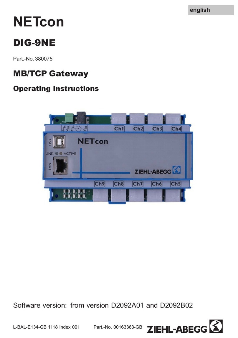
ZIEHL-ABEGG Gateway ZAbluegalaxy User manual

Operating instructions Gateway ZAbluegalaxy / DIG-2019NE •Introduction
L-BAL-312-GB 2020 Index 001 1/23
Gateway
ZAbluegalaxy / DIG-2019NE
Original operating instructions
Preliminary issue!
Store for future use!

Operating instructions Gateway ZAbluegalaxy / DIG-2019NE •Introduction
L-BAL-312-GB 2020 Index 001 2/23
Contents
1 Introduction 5
1.1 Features...............................................................................................................................5
1.2 Functional Overview ............................................................................................................6
1.3 Safety Instructions ...............................................................................................................8
1.4 Installation and Maintenance...............................................................................................8
1.5 EMC Installation...................................................................................................................9
1.6 Ambient and Environmental Conditions...............................................................................9
2 Installation 10
2.1 Mounting ............................................................................................................................10
2.2 Connectors and Operators.................................................................................................11
2.2.1 POWER IN....................................................................................................................11
2.2.2 Serial Port RS485 (DIG-2019NE).................................................................................12
2.2.3 CAN (Gateway ZAbluegalaxy)......................................................................................12
2.2.4 Graphics connector (HDMI)..........................................................................................12
2.2.5 Ethernet Interface .........................................................................................................13
2.2.6 USB host interfaces (USB1-USB4)...............................................................................13
2.2.7 Console (RS232) ..........................................................................................................14
2.2.8 Digital IO .......................................................................................................................14
2.2.9 Audio Video...................................................................................................................15
3 Maintenance 16
3.1 Micro SDcard Replacement...............................................................................................17
3.2 Battery Replacement .........................................................................................................17
4 Appendices 18
4.1 Technical Data...................................................................................................................18
4.2 Dimensions ........................................................................................................................20
4.3 Raspberry GPIO Header....................................................................................................21
4.4 Declaration of conformity ...................................................................................................22
4.5 References.........................................................................................................................22
4.6 Manufacturer reference......................................................................................................23
4.7 Service information ............................................................................................................23

Operating instructions Gateway ZAbluegalaxy / DIG-2019NE •Introduction
L-BAL-312-GB 2020 Index 001 3/23
About these operating instructions
These are the operating instructions for the Gateway ZAbluegalaxy / DIG-2019NE embedded PC.
General notes
Compliance with the following instructions is mandatory to ensure the functionality and safety of the
product. If the following instructions given especially but not limited for general safety, transport, storage,
mounting, operating conditions, start-up, maintenance, repair, cleaning and disposal / recycling are not
observed, the product may not operate safely and may cause a hazard to the life and limb of users and
third parties. Deviations from the following requirements may therefore lead both to the loss of the
statutory material defect liability rights and to the liability of the buyer for the product that has become
unsafe due to the deviation from the specifications.
Structure of the operating instructions
Before installation and start-up, read these instructions carefully to ensure correct use! We emphasize
that these operating instructions apply to specific units only and are in no way valid for the complete
system! Use these operating instructions to work safely with and on the device. They contain safety
instructions that must be complied with as well as information that is required for failure-free operation
of the device. Keep these operating instructions together with the device. It must be ensured that all
persons that are to work on the device can refer to the operating instructions at any time.
Exclusion of liability
To allow for future developments, construction methods and technical data given are subject to
alteration. We do not accept any liability for possible errors or omissions in the information contained
in data, illustrations or drawings provided. We accept no liability for damage caused by misuse,
incorrect use, improper use or as a consequence of unauthorized repairs or modifications.
.
Conventions
If numbers are specified in these operating instructions, they will be either decimal or hexadecimal. We
use C-notation to identify hexadecimal numbers (the 0x prefix).
If we refer to low active signal names, they will be suffixed by a “#” character.
Some parts of the operating instructions contain notices you have to observe to ensure your personal
safety, or to prevent damage to property. These are visually marked with the following alert symbols:
DANGER
Indicates that death or severe personal injury will result if proper precautions are not
taken.
WARNING
Indicates that death or severe personal injury may result if proper precautions are not
taken.
CAUTION
Indicates that minor personal injury can result if proper precautions are not taken.
NOTICE
Indicates that damage to equipment can result if proper precautions are not taken.
Indicates information that we think you should have read to save your time by avoiding
common problems. Important suggestions that should be followed will also be marked
with this sign.

Operating instructions Gateway ZAbluegalaxy / DIG-2019NE •Introduction
L-BAL-312-GB 2020 Index 001 4/23
Acronyms and Abbreviations
EMC Electromagnetic capability.
ESD Electrostatic discharge.
GND System ground potential. Inside the product this is connected to the metal housing,
which might be connected to protective earth by the installation. There exist some
isolated reference grounds for communication interfaces or IO. These reference signals
are referred to as GND-x, where x indicates function.
SELV Safety extra low voltage.

Operating instructions Gateway ZAbluegalaxy / DIG-2019NE •Introduction
L-BAL-312-GB 2020 Index 001 5/23
1 Introduction
1.1 Features
•Raspberry PI 3 Model B+ powered
oBCM2837B0 processor, up to 1400 MHz quad-core ARM 64 bit ARMv8 CPU
o1GB LPDDR2 SDRAM
oHDMI graphics output
o10/100/1000 Mbit/s Ethernet
o4 x USB 2.0
oMicro SDcard socket
oWLAN
oBluetooth
•Console, 9 pin DSUB
•RTC with battery backup
•4 x digital OUT (0.5 A max.), 10...32V externally powered (isolated from logic)
•4 x digital IN (isolated from logic)
Variant DIG-2019NE:
•2x RS485, jumper switchable 120 Ohm termination resistors for each RS485 interface
Variant Gateway ZAbluegalaxy:
•2x CAN, ISO/DIN 11898-2 (isolated from logic)

Operating instructions Gateway ZAbluegalaxy / DIG-2019NE •Introduction
L-BAL-312-GB 2020 Index 001 6/23
1.2 Functional Overview
The processing core of the Gateway ZAbluegalaxy / DIG-2019NE is an unmodified Raspberry PI 3 B+
board. ZIEHL-ABEGG SE specific add-on boards implement the specific features. Refer to figure 1 for
the block diagram of the 2 x CAN variant. Refer to figure 2 for the block diagram of the 2 x RS485
variant.
10/100
BaseT
USB 2.0
User LEDs
USB 2.0
USB 2.0
IIC
EE-
PROM
Temp.-
Sensor
Battery Power
(RTC Only)
USB 2.0
HDMI
Raspberry PI
RTC
RS232
Converter
main
DC/DC
5V, 2A
2.5A
VIN:
9..32
VDC
Isolator
Trans-
ceiver
DC
DC Isolator
CAN
Isolator
SPI
Console
GPIO
GPIO
26pin IO header
VIO: 10..32VDC
2A
High side
switches
4 x 0.5A
Isolation barrier
Isolation barrier
GND-IO
4 4
micro
SD
eFuse
TPS2592AA
UVL:
9.1V ... 10.2 V rising
7.1 V ... 7.9V ... 8.8 V falling
(12% tolerance)
DO
DI
DC/DC
3.3V
GND
PE
1-
Wire
Isolator
Trans-
ceiver
DC
DC
Isolation barrier
CAN
Figure 1: Gateway ZAbluegalaxy / DIG-2019NE block diagram 2 x CAN (Gateway ZAbluegalaxy)

Operating instructions Gateway ZAbluegalaxy / DIG-2019NE •Introduction
L-BAL-312-GB 2020 Index 001 7/23
10/100
BaseT
USB 2.0
User LEDs
USB 2.0
USB 2.0
IIC
EE-
PROM
Temp.-
Sensor
Battery Power
(RTC Only)
USB 2.0
HDMI
Raspberry PI
RTC
RS232
Converter
main
DC/DC
5V, 2A
2.5A
VIN:
9..32
VDC
Isolator
UART
Isolator
SPI
Console
GPIO
GPIO
26pin IO header
VIO: 10..32VDC
2A
High side
switches
4 x 0.5A
Isolation barrier
GND-IO
4 4
micro
SD
eFuse
TPS2592AA
UVL:
9.1V ... 10.2 V rising
7.1 V ... 7.9V ... 8.8 V falling
(12% tolerance)
DO
DI
DC/DC
3.3V
GND
120 Ohm
J300
PE
1-
Wire
RS485
Transceiver
UART
120 Ohm
J400
RS485
Transceiver
Figure 2: Gateway ZAbluegalaxy / DIG-2019NE block diagram 2 x RS485 (DIG-2019NE)

Operating instructions Gateway ZAbluegalaxy / DIG-2019NE •Introduction
L-BAL-312-GB 2020 Index 001 8/23
1.3 Safety Instructions
Refer to page 3 for an explanation of the warning notice system.
- Mounting, electrical connection, and start-up operation may only be carried out by an electrical
specialist in accordance with electrotechnical regulations (e.g. DIN EN 50110 or DIN EN 60204)!
Persons entrusted with the planning, installation, commissioning and maintenance and
servicing in connection with the device must have the corresponding qualifications and skills for
these jobs. In addition, they must be knowledgeable about the safety regulations, EU directives,
rules for the prevention of accidents and the corresponding national as well as regional and in-
house regulations.
- The equipment is to be used solely for the purposes specified and confirmed in the order. Other
uses which do not coincide with, or which exceed those specified will be deemed unauthorised
unless contractually agreed. Damages resulting from such unauthorised uses will not be the
liability of the manufacturer. The user will assume sole liability.
- It is strictly forbidden for work to be carried out on any components while they are connected to
live voltage.
- The owner is obliged to ensure that the device is operated in perfect working order only.
- Electrical equipment must be checked regularly: Loose connections are to be retightened and
damaged lines or cables must be replaced immediately.
- Never clean electrical equipment with water or similar liquids.
1.4 Installation and Maintenance
DANGER: Electrical Shock
Danger to life.
This product operates with 9..32 V DC SELV power supply. Do not connect this product
to an improper power supply (No AC power, no more than 32 V DC/DC or no non-SELV
circuit)!
DANGER: Electrical Shock
Danger to life.
The IO interfaces (connectors) of the product are only suited to be connected to SELV
circuits. Use interfaces (connectors) for their intended use only.
CAUTION: Explosive Risk
The installed computer board is equipped with a Lithium battery.
Danger of explosion if battery is incorrectly replaced. Replace only with battery of the
same or equivalent type.
CAUTION: Fire Risk
The digital IO must be powered by a SELV power supply, that complies with the
requirements of a limited energy source (LPS) (By using an appropriate supply or an
external fuse).
WARNING: Burns Hazard
The product generates considerable amount of heat. The housing transports this heat to
the environment and therefore gets hot. Caution when touching the housing, burns
hazard!

Operating instructions Gateway ZAbluegalaxy / DIG-2019NE •Introduction
L-BAL-312-GB 2020 Index 001 9/23
1.5 EMC Installation
Follow further instructions to grant the EMC compatibility which was used during EMC compatibility tests
to pass the industrial level immunity:
•Connect PE from the multi connector to the EMC shield (DIN rail)
•Connect cable shields for signals running to the multi connector to the EMC shield (DIN rail).
1.6 Ambient and Environmental Conditions
CAUTION: Damage
Do not operate the product beyond the specified ambient conditions
DANGER: Explosive Risk
Do not operate the product in potentially explosive atmosphere.
NOTICE: EMI
This product is a class A device. This product may cause radio interference. In this case
the user must take adequate measures.
NOTICE: System overheating
The cooling concept of the Gateway ZAbluegalaxy / DIG-2019NE is not sufficient to allow
full loading of the Raspberry PI 3 Module processor without system overheating which
leads to clock reduction. Refer to the technical data for details.

Operating instructions Gateway ZAbluegalaxy / DIG-2019NE •Installation
L-BAL-312-GB 2020 Index 001 10/23
2 Installation
WARNING: Burns Hazard
The product generates considerable amount of heat. The housing transports this heat to
the environment and therefore gets hot. Caution when touching the housing, burns
hazard!
The product can be operated with DC power supply from 9 to 32 V.
2.1 Mounting
The Gateway ZAbluegalaxy / DIG-2019NE is intended for wall and 35 mm DIN-rail mount, but can as
well be used on the desk-top. Refer to figure 3 for the recommended mounting orientation.
Do not block heat transfer at this side!
Top
35mm DIN Rail
Do not block heat transfer at this side!
Front Panel
Top
Top
Figure 3: Gateway ZAbluegalaxy / DIG-2019NE mounting options: Desk-top, Wall and DIN Rail

Operating instructions Gateway ZAbluegalaxy / DIG-2019NE •Installation
L-BAL-312-GB 2020 Index 001 11/23
2.2 Connectors and Operators
The 24 pin multi connector provides access to many of the Gateway ZAbluegalaxy / DIG-2019NE
interfaces that are described later.
A suitable mating connector with lock-and-release levers is Phoenix Contact order number 1790580. A
model witch screw locking is available with order number 1790399.
The plug uses spring-cage connection and accepts solid or flexible wires from 0.2 mm² to 1.5 mm². Push
in connection is possible, in case of flexible wires you have to use ferrules for this. If you use ferrules
with plastic sleeve, the maximum wire size reduces to 0.75 mm².
Stripping length for the wires is 10 mm.
If you use ferrules, obey that standard ferrules for 0.75 mm² have only 7 mm length.
2.2.1 POWER IN
The system power supply is located on the multi connector.
123
224
21
22
21
PE
22
PE
23
GND
24
VIN (9..32 VDC)
Table 1: Power Supply connector pins
DANGER
The product may only be operated with power supplies which can be considered SELV
circuits.
Pins 21 and 22 should be connected to EMI protective earth (PE). These contacts are internally
connected to the DC power supply EMI filter and to the D-SUB shell of the console (RS-232). The signal
is doubled to prevent false connection, it only requires one connection. In locations where no EMI noise
is present, the PE connection is not required. The PE has no safety function.
123
2screw
locking
24
lock-and-
release
locking
Figure 4: Multi connector for IO (Power Supply Pins highlighted)

Operating instructions Gateway ZAbluegalaxy / DIG-2019NE •Installation
L-BAL-312-GB 2020 Index 001 12/23
2.2.2 Serial Port RS485 (DIG-2019NE)
The Serial Port is implemented by an SC16IS740 UART. The interface signals are located on the multi
connector, refer to table 2: Serial Port Connector pins.
1
2
11
12
15
16
11
D0-
12
D0+
13
GND0
14
n.c.
15
D1-
16
D1+
17
GND1
18
n.c.
Table 2: Serial Port connector pins
In the RS485 mode the bidirectional differential signals D+ and D- are provided. When the transmitter
is enabled and no data is sent (1=MARK), then D+ > D- (refer to figure 5).
Note that D+ corresponds to pin “A” of the transceiver chip. However, this is signal B according to the
EIA-485 or Profibus standards.
The receiver has the fail-safe input feature, which ensures that no data is received when D+ and D- are
floating or are shorted (e.g. by the termination resistor).
For each serial port, an internal 120 Ohm termination resistor can be enabled between D+ and D- by
shorting jumper J300 or J400. The case must be opened to access these jumpers.
2.2.3 CAN (Gateway ZAbluegalaxy)
The CAN interface is implemented with a MCP2515 controller chip. The interfaces is located on the
multi connector, refer to table 3. The CAN interface signals support ISO 11898-2 (high speed) and are
isolated from system logic, as result it is always required to connect 13 GND-CAN and 17 GND1-CAN
to the belonging CAN ground.
1
2
11
12
15
16
11
CAN-H
12
CAN-L
13
GND-CAN
14
n.c.
15
CAN1-H
16
CAN1-L
17
GND1-CAN
19
n.c.
Table 3: CAN connector pins
There are no internal 120 Ohm CAN termination resistors provided.
2.2.4 Graphics connector (HDMI)
Provided by Raspberry PI board.
D+
D- 1 = Mark 0 = Space 1 = Mark
Transmitter
idle
Startbit Databit 0Transmitter
tristate
"0V"
Voh
Vol
Figure 5: RS485 signalling

Operating instructions Gateway ZAbluegalaxy / DIG-2019NE •Installation
L-BAL-312-GB 2020 Index 001 13/23
2.2.5 Ethernet Interface
Ethernet interfaces of the Raspberry PI. The Ethernet physics is 10/100BaseT, available through the
shielded modular jack. A twisted pair cable can be used to connect to this port.
The two LEDs indicate Ethernet status as follows:
LED1
LED2
No activity
No Link
Activity
10/100 MBit Link
NOTICE
If your Ethernet cable is long (normative limit = 30 m) or leaves a building, then an
additional protection against surges is required.
Add an external surge protector is such cases. E.g. ground the Ethernet cable shield
where it enters the building or your cabinet.
If you just connect to a nearby switch, such countermeasures are not required.
2.2.6 USB host interfaces (USB1-USB4)
Two USB interfaces are available at the connector panel.
1
+5V, IMAX = 500 mA, 500 mA for all ports
2
USB-
3
USB+
4
GND
Table 5: USB host connector
NOTICE
Although each port can deliver supply current of 500 mA, the overall load on USB1 to
USB4 interfaces must be limited to 500 mA to prevent power supply from overheating
and the +5V internal fuse from triggering.
If you draw excessive power from USB ports or short circuit USB power supply outputs,
then the Raspberry PI board will temporarily shut off the USB power supply and retry
every 2 seconds.
1
RD+
5
n.c.
2
RD-
6
TD-
3
TD+
7
n.c.
4
n.c.
8
n.c.
Table 4: Ethernet connector
1

Operating instructions Gateway ZAbluegalaxy / DIG-2019NE •Installation
L-BAL-312-GB 2020 Index 001 14/23
2.2.7 Console (RS232)
The RS232 (Console) serial interface is provided by the Raspberry PI board. The connector is a
standard 9 pin D-SUB plug, but the interface is connected with two wires only, table 6 shows the pinout.
9pin male D-Sub
1
n.c.
6
n.c.
2
RxD
7
n.c.
3
TxD
8
n.c.
4
n.c.
9
n.c.
5
GND
Table 6: Console (RS232) connector
2.2.8 Digital IO
Digital input (DI1-DI4) and output (DO1-DO4) ports are provided on the multi IO connector (refer to table
7).
1
2
9
10
1
DO4
2
DO3
3
DO2
4
DO1
5
GND-IO
6
VIO (10..32 VDC)
7
DI4
8
DI3
9
DI2
10
DI1
Table 7: Digital IO connector pins
CAUTION
The digital IO must be powered by a SELV power supply, that complies with the
requirements of a limited energy source (LPS) (By using an appropriate supply or an
external fuse).
The digital inputs and outputs are isolated from system power supply. Refer to figure 6: digital IO detailed
schematic for detailed schematic.
The digital input signals (DI1-DI4) refer to GND-IO and have an input impedance of about 5 kOhm.
Switching level for low is ≤4V and high ≥9V. The digital inputs do not require VIO to be present.
The output driver supports resistive and inductive loads.
NOTICE
When using inductive loads, the output driver has internal clamping to demagnetize the
load. This clamps the output pin to about 55 V below VIN. When using this feature, very
carefully evaluate that the demagnetization energy does not overheat the output driver.
VIO
VN330SP
Polarity
Reversal
Protection
DO
Output GPIO
GND-IO
DI
Input GPIO
Load
Figure 6: digital IO detailed schematic
1
6

Operating instructions Gateway ZAbluegalaxy / DIG-2019NE •Installation
L-BAL-312-GB 2020 Index 001 15/23
Parameters to check are the switching frequency, the load current, the load inductance
and VIO voltage. Refer to the VN330SP datasheet for more information. If in doubt, add
external clamping circuits.
2.2.9 Audio Video
The combined audio and analogue video connector are not accessible on the Gateway ZAbluegalaxy /
DIG-2019NE.

Operating instructions Gateway ZAbluegalaxy / DIG-2019NE •Maintenance
L-BAL-312-GB 2020 Index 001 16/23
3 Maintenance
NOTICE
Always follow common ESD practice when you service the product!
To open the housing, follow these steps (refer to figure 7):
•Disconnect all connectors
•Remove both bolts on the front RS232 DSUB connector
•Remove all screws on the backside (DIN rail clip or mounting plate)
•Insert the tip of a small screwdriver into the hole above the USB ports and unclip the two case
parts
•Pull the lower case part away from the upper case
Task
Remarks
Replace µSD-card
Remove DIN rail clip and/or wall
mount bracket
Change jumper settings
Remove case bottom part
Replace Battery
Complete disassembly
NOTICE
Remove the micro SDcard before you attempt to remove the Raspberry PI module from
the housing.
Remove these
2 bolts
Unsnap and remove bottom
half of the housing
Figure 7 :Gateway ZAbluegalaxy / DIG-2019NE
case bottom part removal
micro-
SDcard
Back Panel
Figure 8: Gateway ZAbluegalaxy / DIG-2019NE
micro SDcard location

Operating instructions Gateway ZAbluegalaxy / DIG-2019NE •Maintenance
L-BAL-312-GB 2020 Index 001 17/23
3.1 Micro SDcard Replacement
NOTICE
Power must be turned off before removing or inserting the micro SDcard
Refer to figure 8 to identify the location of the Micro SDcard. Remove the DIN rail clip and/or the wall
mount bracket if necessary.
3.2 Battery Replacement
CAUTION
The installed computer board is equipped with a Lithium battery.
Danger of explosion if battery is incorrectly replaced. Replace only with battery of the
same or equivalent type (3-volt lithium coin cell battery).
•Do not attempt to recharge the battery.
•Do not disassemble, crush, puncture, short external contacts, or dispose of in
fire or water.
Compatible battery type: CR2032 (3 Volt lithium coin cell battery)
The battery is used for backing up the system time when the power supply is removed.
1. Turn off the computer properly through the operating system, then turn off any external devices.
2. Disconnect the power supply from the power inlet and disconnect any external devices.
3. Disassemble the housing (refer chapter 3) and locate the battery on the ZIEHL-ABEGG SE
board.
4. Remove the battery from the holder (see figure 9)
5. Insert the new battery (see figure 9)
6. Re-assemble the housing
1 2
1. Removal: Insert screwdriver at right side and bend so that the battery
pops outs. Use only gentle force, otherwise the battery holder might be
damaged.
The use a plastic tool is preferred to avoid shorting the battery
2. Insertion: Align new battery to the left side of the holder (below the
hooks) and gently press down on the right side of the battery until the
battery snaps into the holder.
Figure 9: Removing and replacing coin cell battery

Operating instructions Gateway ZAbluegalaxy / DIG-2019NE •Appendices
L-BAL-312-GB 2020 Index 001 18/23
4 Appendices
4.1 Technical Data
Only Raspberry features usable on Gateway ZAbluegalaxy / DIG-2019NE are listed.
Processing Core
CPU
BCM2837B0, up to 1400 MHz quad-core 64bit ARMv8 Cortex A53
Memory
Main Memory
1GB LPDDR2 SDRAM
Storage
Micro SDcard
1 x internal socket
External Interfaces
Video
1 x HDMI (Maximum resolution 1920x1080)
Ethernet
1 x 10/100 Mbit/s Ethernet (LAN9512, USB based)
WLAN
As defined by Raspberry PI 3 Module
Bluetooth
As defined by Raspberry PI 3 Module
USB
4 x USB2.0
Serial Port (Console)
Console (RPI defined)
•1x RS232 (2 wire)
CAN
(Gateway ZAbluegalaxy)
Part No. 357323
2x MCP2515 controller
•ISO/DIS 11898-2 (isolated from logic)
Serial Port (RS485)
(DIG-2019NE)
Part No. 380109
SC16IS740 controller
•2x RS485
Digital IO
•4 x digital OUT (0.5 A max.), 10…32 V
•4 x digital IN
•Isolated from system ground
Indicators and Switches
User LEDs
2 programmable LEDs (red, green)
System
Housing
Plastics (UL-VO)
RTC
MCP7940
Battery
CR 2032, for real time clock
Power Requirements
Power Supply
DC power, 9 .. 32 V
Inv.-pol. Protection
Yes
Fuse
Internal 2.5 A melting fuse in DC in, GND is unfused
Internal 3.0 A eFuse in +5V supply of Pi 3 module
Potential Separation
No, GND is connected to connector shells and PE contact
Inrush Current (max)
TBD
Power Dissipation
Without external load or expansion cards
4 x stress-ng matrix-copy 128 @ 600 MHz : 4.2 W (typ)
1 x stress-ng matrix-copy 128 @ 1400 MHz : 4.3 W (typ)
4 x stress-ng matrix-copy 128 @ 1400 MHz : 9.5 W = not supported

Operating instructions Gateway ZAbluegalaxy / DIG-2019NE •Appendices
L-BAL-312-GB 2020 Index 001 19/23
External Load Capabilities
+5V (USB)
Max. 500 mA per USB port, max 500 mA for all USB ports
Environmental Specifications
To specify an ambient operating temperature for reliable 24/7 industrial operation, the CPU and
GPU load are two very important factors. If all CPU cores are idle all the time, then the
maximum specified ambient temperature can be much higher than in a maximum CPU
utilization application.
The new BCM2837B0 system-on-chip has much more computation power than its
predecessors, but also gets far, far hotter. In high CPU load scenarios, the clock is dynamically
increased from 600 MHz to 1400 MHz and then produces so much heat, that even at room
temperature the clock would automatically throttle down to 600 MHz after several minutes to
prevent overheating.
Because of the thermal limitations of the used standard Raspberry Pi 3 Model B+ single board
computer, the form factor of the casing and the economic limitations in this entry level system,
no extensive passive cooling solution can be used. The internal baseboard designed by us
providing the power supply and the I/Os and two fieldbuses to the Raspberry Pi board, would
allow an ambient operating temperature from -25…60°C but the Raspberry Pi board is the
limiting factor.
The embedded PC uses a passive heat sink on the BCM2837B0 chip and therefore is it not
possible to use all of the computation performance the BCM2837B0 provides. The system
power consumption ranges from 3.0 W (average when idle) to 9.5 W (maximum under stress).
To prevent CPU overheating and throttling, the maximum system power consumption should
not be higher than about 4 W. In most real world use cases of this embedded computer, the
average power consumption will be lower than this limit, but if constant CPU performance is
important for your application, then limiting the maximum CPU frequency to 600 MHz in
configuration file /boot/config.txt is one possibility to achieve this. Without limiting the maximum
CPU frequency, the CPU will dynamically change the frequency depending on the CPU
temperature (see commands: vcgencmd measure_temp and vcgencmd measure_clock arm).
Ambient operating
Temperature
0 .. +40 °C (vertical orientation / wall and DIN rail mounting)
0 .. +35 °C (horizontal orientation / desk-top mounting)
at sea level, derated by 1 °C per 300 m above sea level to
a maximum of 2000 m.
the above temperature ratings are defined under the following CPU
load:
•No GPU load
•4 cores loaded at 600 MHz or 1 core loaded at 1400 MHz,
where the load per core is comparable to that of the Linux
stress-ng utility
•The above numbers are without safety margins to
compensate process variations of the Broadcom SoC
•More load will bring the CPU Junction temperature above
80°C and the CPU will reduce clock frequency towards 600
MHz. The system will not overheat under such conditions.
Temperature storage
-20…+75 °C
Humidity
5…95 % r.H., non condensing
Protection Class
IP20
Physical Dimensions
Size (WxHxD)
99.8 x 30.0 x 96.7 mm
Weight
200 g

Operating instructions Gateway ZAbluegalaxy / DIG-2019NE •Appendices
L-BAL-312-GB 2020 Index 001 20/23
4.2 Dimensions
Refer to figure 10 for the housing dimensions.
The Gateway ZAbluegalaxy / DIG-2019NE is delivered with the following mounting options:
•DIN rail clip (not assembled)
•Wall mount bracket (not assembled)
•Self-adhesive rubber bumpers (not assembled)
Note, that you will not normally use both the DIN rail clip and the wall mount bracket at the same time.
91,70 mm
3,00 mm
11,00 mm
30,00 mm
99,80 mm
4,00 mm
2,60 mm
118,60 mm
138,60 mm
DIN
Rail
Clip
Wall mount
bracket
Figure 10: housing dimensions
This manual suits for next models
1
Table of contents
Other ZIEHL-ABEGG Gateway manuals