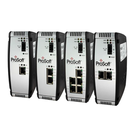
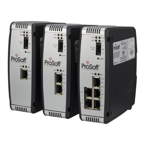
ProSoft Technology ProSoft 1560 User manual

U S E R
M A N U A L
1560
1560
U S E R
M A N U A L

ProSoftTechnology, Inc
1560-MBP Modbus Plus SCANport Gateway
Catalog Numbers:
1560-MBP-1 Modbus Plus SCANport Gateway - 115 VAC
1560-MBP-2 Modbus Plus SCANport Gateway - 24VDC
Table of Contents
Quick Start Guide ..................................................................................... 4
Revisions ................................................................................................. 5
1 Product Specifications .................................................................... 6
1.1 Mobus Plus Specifications ........................................... 6
1.2 General Specifications ................................................. 6
2 Modbus Plus Functionality .............................................................. 8
2.1 Modbus Plus Communications ..................................... 8
2.1.1 Supported MSTR Programming Commands ................. 8
2.1.2 Modbus Register Map .................................................. 9
3 Hardware Setup ............................................................................... 10
3.1 1560-MBP Card Setup................................................. 10
3.1.1 Connecting Power to the 1560-MBP Card...................... 10
3.1.2 Dip Switch Configuration .............................................. 10
4. Programming Considerationations ................................................. 15
4.1 Writing to the 1560-MBP .............................................. 15
4.1.1 Global Data Enabled - MSTRType 5 ............................. 15
4.1.2 Host IssuedWrite Commands - MSTRType 1 ............... 18
4.2 Reading from the 1560-MBP ........................................ 19
4.2.1 Global Data - MSTRType 6 .......................................... 19
4.2.2 Host Issued Read Commands - MSTRType 2 ............... 20
4.3 The MBP Status Registers (40021 to 40100) ................. 22
5.Troubleshooting .............................................................................. 25
5.1 LED Locations............................................................. 25
5.1.1 LEDTroubleshootingTable ........................................... 25
5.2 MBPSTAT Diagnostics ................................................. 27
6. Cable Diagram ................................................................................ 28
7.Technical Support ........................................................................... 29
7.1 Technical Support Contacts .......................................... 29
Appendix A ........................................................................................ 30
1560-MBP Modbus Register Map............................................... 30
Appendix B ........................................................................................ 31
Device Specific Hints ................................................................. 31
Appendix C ........................................................................................ 33
Single Drive Peer COP Application Example ............................... 33
Appendix D ........................................................................................ 39
Mounting and SCANport Cabling Instructions .............................. 39
Appendix E......................................................................................... 41
Repair andWarranty ........................................................................... 42
3
Contents
Please Read This Notice
Successful application of the 1560-MBP card requires a
reasonable working knowledge of the Allen-Bradley hardware to
be interfaced with, and the application in which the combination
is to be used. For this reason, it is important that those
responsible for implementing the 1560-MBP satisfy themselves
that the 1560-MBP and Allen-Bradly hardware combination will
meet the needs of the application without exposing personnel or
equipment to unsafe or inappropriate working conditions.
This manual is provided to assist the user. Every attempt has
been made to assure that the information provided is accurate
and a true reflection of the product’s installation requirements.
In order to assure a complete understanding of the operation of
the 1560-MBP, the user should read all applicable
documentation on the operation of the Allen-Bradley hardware.
Under no conditions will ProSoft Technology, Inc. be responsible
or liable for indirect or consequential damages resulting form
the use or application of the 1560-MBP product.
Reproduction of the contents of this manual, in whole or in part,
without written permission from ProSoft Technology, Inc. is
prohibited.
Information in this manual is subject to change without notice
and does not represent a commitment on the part of ProSoft
Technology, Inc. Improvements and/or changes in this manual
or the product may be made at any time. These changes will be
made periodically to correct technical inaccuracies or
typographical errors.
WARNING
The 1560-MBP card will allow remote access to
commands in the Allen-Bradley drives and other
Scanport compatible devices. The User is
responsible for assuring that any applicable regulations
concerning the remote operation of
equipment are adhered to.
© ProSoft Technology, Inc. 1997, 1998
Modbus Plus is a Trademark of Schneider Automation

4
Contents
Quick Start Guide
In this section we have assembled a simple step-by-step procedure for
installing and making the 1560-MBP unit operational. This discussion
presumes that the application decisions such as Modbus Plus
addressing and hierarchy, SCANport cable length, etc. have been
addressed prior to this point.
Step-by-Step
The following steps will allow the 1560-MBP to be setup in the shortest
period of time (the following steps refer to the Allen-Bradley drive
implementation. Similar steps are followed when interfacing to other A-B
Power Division products):
1 Set the dip switches
The 1560-MBP dip switch positions are detailed in Section 3
2 Mount the 1560-MBP on the DIN rail
See Appendix D for mounting instructions.
3 Connect power to the 1560-MBP
Refer to Section 3
4 Setup the Drive hardware
Refer to the appropriate drive manual to connect control and
power to the drive. This aspect of the drive installation is out
of the scope of this manual.
5 Setup the Drive parameters
See Appendix B of the manual to setup the drive parameters
6 Install the SCANport cable between the drive and the
1560-MBP.
7 Connect the Modbus Plus communication cable between
the host system and the 1560-MBP. The procedure follows
standard Modbus Plus cabling practices.
Quick Start Guide

5
Contents
Revisions
3/15/97 Rev 1.0
Initial Release
5/5/97 Rev 1.1
Modify product to allow slave addresses within any
group of 16 slave addresses on one PLC Host
when using Global Data. Also protect Control and
Reference words from overwrite if Global Control
Enabled.
Revisions
1/98 Upgrade User Manual

6
Contents
1 Product Specifications
The ProSoft Technology, Inc. 1560-MBP card is a hardware
product designed to be a communications front end for Allen-
Bradley SCANport compatible products (1336 Plus/Force/
Vector, 1305, SMC Dialogue Plus, SMP3, etc.).
The product includes the following functionality:
1.1 Modbus Plus Specifications
•Protocol modes:
Modbus Plus using licensed Schneider
Automation technology
•Supported Modbus Plus Operations:
MSTR Type 1 - Write Data
MSTR Type 2 - Read Data
MSTR Type 5 - Write Global Data
MSTR Type 6 - Read Global Data
•Supports Global Database Control from Host PLC
In this mode, the 1560-MBP will look for Control
Word and Reference in the selected Host Global
Database
•Pre-assigned Modbus memory map
Read/Write
Command Control/Frequency
Datalinks Out :A to D
Up to 2000 drive parameter values
Read Only
Status/Feedback
Datalinks In : A to D
1.2 General Specifications
•Configuration via dip switches
Slave Address : 1 to 64
Host Address : 1 to 64
Global Database Control Enable
Fault on Loss of Modbus Plus Enable
SCANport Messaging Options
No Datalinks
Datalinks A only
Datalinks A and B only
Datalinks A, B, C, D
•Available packages:
Enclosed Power supplied externally (120 VAC)
Enclosed Power supplied externally (24 VDC)
Chapter 1 — Product Specifications

7
Contents
•Mounting :
DIN Rail mounting
•Dimensions :
44 mm (width) x 76 mm (height) x 123 mm (depth)
•Communication port connections:
Modbus Plus - Female 9-pin D shell connector
SCANport - Standard SCANport connector
•Status LED
SCANport Status (bi-color Red/Green)
Modbus Plus Status (green)
•Current Consumption: 65 ma at 24 VDC
•Input Voltage
85 to 264 VAC, 1 Phase, 45 to 63 Hz
24 VDC
•Operating Temp 0 to 50°C
•Storage Temp -40 to 85°C
Chapter 1 — Product Specifications

8
Contents
2 Modbus Plus Port Functionality
2.1 Modbus Plus Communications
The 1560-MBP Modbus Plus card supports the Modbus Plus
protocol using proprietary technology licensed from Schneider
Automation. With the Modbus Plus capability, the module is
able to communicate data from Allen-Bradley SCANport
compatible devices to a Modbus Plus host PLC, and vice-versa.
The following discusses the functional capabilities of the 1560-
MBP card.
2.1.1 Supported MSTR Programming Commands
The 1560-MBP uses several of the available MSTR ladder
logic commands to transfer data when using a Modicon PLC.
These are overviewed below:
Read Data:The following types of data read commands are
supported:
MSTR Type 2 Read Data
This command reads data from any place within the
Modbus Register map. This command allows a Modbus
host to selectively read data from the 1560-MBP as
required for the application.
MSTR Type 6 Read Global Data
This command gets data from the Global Data being sent
from the 1560-MBP. The 1560-MBP returns 2 to 10 words
of Global data. This is the fastest method of reading
values from the MBP.
Write Data:The following data write commands are supported:
MSTR Type 1 Write Data
This command writes data to any place within the 1560-
MBP Modbus Register map. This command can be used to
selectively write configuration values to the SCANport
device. In addition, if the Global Data Command Enable dip
switch is disabled, this command can be used to write to
the SCANport Control and Reference words (Modbus
addresses 40001 to 40010).
Chapter 2 — Modbus Plus Port Functionality

9
Contents
MSTR Type 5 Write Global Data
This command is used in a host processor to ‘publish’ Global
Data which all slaves on the Modbus Plus highway may
access.The 1560-MBP units can be configured to read the
Control and Reference values from this Global Data table.
2.1.2 Modbus Register Map
A pre-defined register map has been provided in the 1560-
MBP unit. This map is detailed in Appendix A, and shown
below. The full memory map is dependent on the A-B device
which is connected to the 1560-MBP unit.
On power-up, the 1560-MBP unit polls the remote device
and determines the maximum number of parameters that
exist in the SCANport device. If the number is greater than
2000 the parameter list is limited to 2000.
Chapter 2 — Modbus Plus Port Functionality
Control, Reference
and Datalink IN
Miscellaneous
Parameter
40001
40011
40021
40101
4xxxx
Status, Reference
and Datalink OUT
(1)(2)
(3)
(1)
Note that 40001 and 40002 are only accessible with MSTR
Type 1 if ‘Global Control’ is disabled in the 1560-MBP.
Represents Control and Reference Words which are
controlled by host when ‘Global Control’ is enabled.
Words 40011 up to 40020 are ‘Published’ by 1560-MBP in the
mode Global Data space. A host can access these values
using a MSTR Type 6 instruction or Peer Cop (see Appendix
C), or an MSTR Type 2 data read.
(2)
(3)
1560-MBP Modbus
Address Space
Host
Write
MSTR 1 Read
MSTR 2
Host
Global
Write
MSTR 5
Global
Read
(to Host)
MSTR 6

10
Contents
Chapter 3 — Hardware Setup
L
N
G
115 VAC Hot
115 VAC Neutral
Ground
+
Com
G
24 VDC +
24 VDC Common
Ground
Host & Slave Address
Add values of switches and then add 1 to total
to calculate address
Examples
SW
1
2
3
4
5
6
Value
1
2
4
8
16
32
Address 1
Address 8
6 5 4 3 2 1
6 5 4 3 2 1
(0+0+0+0+0+0)=0+1=1
(0+0+0+4+2+1)=7+1=8
ON
OFF
ON
OFF
HOST SLAVE
8 7 8 7 8 7 8 7
Datalinks
A,D,C,D A&D only A only NONE
ON
ON
OFF
OFF
ON
OFF
8 7 6 5 4 3 2 1 8 7 6 5 4 3 2 1
Fault on Loss of
Modbus Plus
Global Database
Control
88
ON=Enable
OFF=Disable
77
ON=Enable
OFF=Disable
3 Hardware Setup
3.1 1560-MBP Card Setup
3.1.1 Connecting Power to the 1560-MBP Card
Connecting power requires a simple termination of the 120
VAC or 24 VDC cable to the front of the module. The
connections are shown in the following diagram:
3.1.2 Dip Switch Configuration
Configuration of the 1560-MBP consists of setting up some
dip switches. The dip switches are as follows:
Please note that dip switch configuration is read
by the 1560-MBP during the power up process.
Power must be cycled if dip switches are changed
under power.

11
Contents
Switch SW 1
Function Description Details
Datalink
Options
Host
PLC
Address
(when Global
Data Control
Enabled)
Allows the User to
select the level of
Datalink support the
1560-MBP unit will
have when talking to
the SCANport device.
Some devices do not
support Datalinks, in
which case the ‘No
Datalinks’ option must
be selected.
If the Global Data
Control is Enabled
(SW2-7 is set to 1)
then the 1560-MBP
must be told which
Host PLC Global
Database to get the
control values from.
To select the
appropriate Host,
determine the Host’s
Modbus Plus address
and select that
address using the dip
switches SW1- 1 to 6.
SW1-7 and 8
8 7
off off No Datalinks
off on Datalink A only
on off Datalink A&B only
on on Datalink A,B,C,D
SW1-1 to 6
1 Address Bit 0 Value = 1
2 Address Bit 1 Value = 2
3 Address Bit 2 Value = 4
4 Address Bit 3 Value = 8
5 Address Bit 4 Value = 16
6 Address Bit 5 Value = 32
Example Addresses = 1 to 64
6 5 4 3 2 1 Address
off off off off off off 1
off off off off off on 2
off off off off on off 3
off off off off on on 4
off off off on off off 5
off off off on off on 6
off off off on on off 7
off off off on on on 8
off off on off off off 9
off off on off off on 10
off off on off on off 11
off off on off on on 12
off off on on off off 13
off off on on off on 14
off off on on on off 15
off off on on on on 16
off on off off off off 17
off on off off off on 18
off on off off on off 19
off on off off on on 20
off on off on off off 21
off on off on off on 22
off on off on on off 23
off on off on on on 24
off on on off off off 25
off on on off off on 26
off on on off on off 27
Chapter 3 — Hardware Setup

12
Contents
Chapter 3 — Hardware Setup
off on on off on on 28
off on on on off off 29
off off on on off on 30
off on on on on off 31
off on on on on on 32
on off off off off off 33
on off off off off on 34
on off off off on off 35
on off off off on on 36
on off off on off off 37
on off off on off on 38
on off off on on off 39
on off off on on on 40
on off on off off off 41
on off on off off on 42
on off on off on off 43
on off on off on on 44
on off on on off off 45
on off on on off on 46
on off on on on off 47
on off on on on on 48
on on off off off off 49
on on off off off on 50
on on off off on off 51
on on off off on on 52
on on off on off off 53
on on off on off on 54
on on off on on off 55
on on off on on on 56
on on on off off off 57
on on on off off on 58
on on on off on off 59
on on on off on on 60
on on on on off off 61
on off on on off on 62
on on on on on off 63
on on on on on on 64
Switch SW 2
Function
Fault on
Loss of
Modbus
Plus
When enabled, the
1560-MBP will fault the
connected SCANport
device if the Control
Word is not updated
within 10 seconds.
Note that the fault is not
enabled until after
Modbus Plus
communications have
been initially
established.
Details
Description
SW2-8
Off = Disable fault on loss
of Modbus Plus
On = Enable fault on loss of
Modbus Plus

13
Contents
Chapter 3 — Hardware Setup
Switch SW 2 (cont’d.)
Function
Global Data
Base Control Enables the 1560-MBP
to automatically gather
the Control Word and
Speed Reference
values from the
selected Host Global
Database.
When enabled, the
1560 will use two
words from the global
database based on the
selected Modbus Plus
address (SW1-1 to 6).
When disabled, the
Host must write into
1560 unit's Modbus
register table at
addresses 40001/2 to
write the Control word
and speed reference
values
Details
Description
SW2-7
Off = Disable Global Data
Base Control
On = Enable Global Data
Base Control
Important
A maximum of 16 1560-MBP
units can be enabled in the
Global Control Mode on one
PLC network. These 16 units
must be addressed within one
of the following ranges:
1 to 16
17 to 32
33 to 48
49 to 64
Selects the Modbus
Plus Address for the
1560-MBP unit. Each
node must have a
unique address. Note
that the addresses will
be one higher than the
binary value selected by
the dip switches.
It is recommended that
address 1 not be used
to avoid possible
confusion when using a
local default address of
1 at a controller node
programming panel.
Modbus Plus
Address
(1560-MBP
unit address)
SW2-1 to 6
1 Address Bit 0 Value = 1
2 Address Bit 1 Value = 2
3 Address Bit 2 Value = 4
4 Address Bit 3 Value = 8
5 Address Bit 4 Value = 16
6 Address Bit 5 Value = 32
6 5 4 3 2 1 Address
off off off off off off 1
off off off off off on 2
off off off off on off 3
off off off off on on 4
off off off on off off 5
off off off on off on 6
off off off on on off 7
off off off on on on 8
off off on off off off 9
off off on off off on 10
off off on off on off 11
off off on off on on 12
off off on on off off 13
off off on on off on 14
off off on on on off 15
off off on on on on 16
off on off off off off 17
off on off off off on 18

14
Contents
Chapter 3 — Hardware Setup
off on off off on off 19
off on off off on on 20
off on off on off off 21
off on off on off on 22
off on off on on off 23
off on off on on on 24
off on on off off off 25
off on on off off on 26
off on on off on on 27
off on on off on on 28
off on on on off off 29
off off on on off on 30
off on on on on off 31
off on on on on on 32
on off off off off off 33
on off off off off on 34
on off off off on off 35
on off off off on on 36
on off off on off off 37
on off off on off on 38
on off off on on off 39
on off off on on on 40
on off on off off off 41
on off on off off on 42
on off on off on off 43
on off on off on on 44
on off on on off off 45
on off on on off on 46
on off on on on off 47
on off on on on on 48
on on off off off off 49
on on off off off off 50
on on off off on off 51
on on off off on on 52
on on off on off off 53
on on off on off on 54
on on off on on off 55
on on off on on on 56
on on on off off off 57
on on on off off on 58
on on on off on off 59
on on on off on on 60
on on on on off off 61
on off on on off on 62
on on on on on off 63
on on on on on on 64

15
Contents
4 Programming Considerations
Transferring data to/from the 1560-MBP is performed either
using the standard MSTR instruction, or using the Peer Cop
functionality available in some Schneider processors. (Note that
Peer Cop functionality is somewhat limited. See Appendix C.)
Specifically, the following functionality is supported:
MSTR Type 1 - Write data
MSTR Type 2 - Read data
MSTR Type 5 - Write Global Data
MSTR Type 6 - Get Global Data
The following sections will detail the programming requirements
for each of these commands, as well as discuss speed trade-
offs between the different commands. An application note
detailing the configuration of a Peer Cop solution is also
available in Appendix C.
4.1 Writing to the 1560-MBP
4.1.1 Global Data Enabled - MSTRType 5
If Global Data Control Mode is enabled, the 1560-MBP will look
to the Host’s Global Data space for the Control and Reference
values. All other values must be written by the host using the
MSTR Type 1 instruction in the PLC.
The location of the Control and Reference values in the Global
Data is determined by the 1560-MBP Modbus Plus address.
The 1560-MBP uses the following algorithm to obtain the values
:
If Modbus Plus Address < 17
GlobalTable Index = ( Modbus Plus Address - 1 ) * 2
else if Modbus Plus Address < 33
GlobalTable Index = ( Modbus Plus Address - 17 ) * 2
else if Modbus Plus Address < 49
GlobalTable Index = ( Modbus Plus Address - 33 ) * 2
else if Modbus Plus Address < 65
GlobalTable Index = ( Modbus Plus Address - 49 ) * 2
Note
The Global Data Table has a limit of 32 words,
therefore there can only be 16 1560-MBP
units with Global Control Enabled on one
Host processor. Care must be exercised that
all 16 Global Control Enabled 1560-MBP
devices are in the same block of addresses.
Chapter 4 — Programming Considerations

16
Contents
Relationship between Global Data from Host and 1560-MBP Control & Reference
Words: The diagram shows an example if Slave 37 was configured for Global Data
Control and where the Control/Reference words would come from in the Global Data
from a Host.
The following table details the relationship between the Modbus Plus
addresses and the Global Data Table:
Chapter 4 — Programming Considerations
Control Word
Reference
Adaptor I/O-A1
Adaptor I/O-A2
Adaptor I/O-B1
Adaptor I/O-B2
Adaptor I/O-C1
Adaptor I/O-C2
Adaptor I/O-D1
Adaptor I/O-D2
Word
0
2
4
6
8
10
12
30
Global Data Sent from Host
(2 words per slave)
Slave 48
From Global Data Table
MSTR Type 1 accessible
only
Global Write Space
(Slave 37)
Slave 33
1,17,33,49 0
1
2,18,34,50 2
3
3,19,35,51 4
5
4,20,36,52 6
7
5,21,37,53 8
9
6,22,38,54 10
11
7,23,39,55 12
13
8,24,40,56 14
15
9,25,41,57 16
17
10,26,42,58 18
19
11,27,43,59 20
21
12,28,44,60 22
23
1560-MBP
Modbus Plus
Address
Global Data
Table
Index Description
Control Word
Reference Word
Control Word
Reference Word
Control Word
Reference Word
Control Word
Reference Word
Control Word
Reference Word
Control Word
Reference Word
Control Word
Reference Word
Control Word
Reference Word
Control Word
Reference Word
Control Word
Reference Word
Control Word
Reference Word
Control Word
Reference Word
Slave 37
1560-MBP

17
Contents
Chapter 4 — Programming Considerations
13,29,45,61 24
25
14,30,46,62 26
27
15,31,47,63 28
29
16,32,48,64 30
31
1560-MBP
Modbus Plus
Address
Global Data
Table
Index Description
Control Word
Reference Word
Control Word
Reference Word
Control Word
Reference Word
Control Word
Reference Word
This instruction “publishes” Global Data on the Modbus Plus network
from the Host PLC. Up to 32 words can be transmitted from the Host,
allowing up to 16 1560-MBP units to be controlled. When the 1560-MBP
reads the Global Data it first examines the source node address to
assure it matches the dip switch configured Host Node Address, and
then retrieves the two words that relate to its node from the packet.
enable -
abort -
Modicon Programming Example - MSTR 5
- active
40400
40410
MSTR
00032
- error
- success
Contents of registers in control block
40400 = 5 Global write data instruction
40401 = 0 Error code
40402 = 32 Global Data block length
(Max 32 words)
40403 = 0 N/A
40404 = 0 N/A
40410 = Source of the Global Out Data
40410
40411
40412
40413
•
•
40420
40421
•
•
40440
40441
Controller
Address Node Description
Control Word
Reference Word
Control Word
Reference Word
Control Word
Reference Word
33
34
•
••
•
37
Control Word
Reference Word
•
••
•
48

18
Contents
4.1.2 Host IssuedWrite Commands - MSTRType 1
If the Global Data Control Mode is not enabled, the 1560-MBP
will not look to the Global Data Table to obtain the Control and
Reference values. In this mode, the Host PLC must execute a
write command (MSTR Type 1) to the 1560-MBP to register
addresses 40001 and 40002, per the following drawing, to
control the drive.
MSTR Type 1 Accessible Data Registers: The memory map for the registers
which a PLC programmer can access from the 1560-MBP using the MSTR
Type 1 command. Note that a write to the Read Only space between 40011
and 40100 will place an Error Code in the MBP Status register.
Write Data – Control Reference & Data Link IN
Parameter Register Space
This register space contains the parameter table from the
SCANport device.This paramaters are stored in their
numerical order (example):
40101 = Parameter #1
40102 = Parameter #2
The full length of this space is a function of the SCANport
device connected. Max size is 2000 parameters.
40001
40011
40021
40101
4xxxx
Chapter 4 — Programming Considerations
In the example (at the bottom of the previous page) the 1560-MBP
responding at Node 37 would retrieve its control and reference values
from the 8th and 9th words of the Global Data block. In the Host PLC we
have placed this data in registers 40418 and 40419, as this corresponds
to the 8th and 9th position in the Global Data packet.
Not Accessible
by Write Command

19
Contents
4.2 Reading from the 1560-MBP
Reading data from the 1560-MBP is independent of the Global
Data Control mode selection. There are two methods for
obtaining data from the 1560-MBP units as outlined in the
following section.
4.2.1 Global Data - MSTRType 6
The 1560-MBP publishes Global Out Data which can be accepted by any
other node on the Modbus
Plus port.The structure of the Global Data sent
out in is as follows
:
Global Data from each 1560-MBP unit: Note the minimum
length of 2 words can be increased up to 10 words by
selectively enabling Datalinks using the dip switches
This instruction would write one value into parameter 19 of the device attached to
1560-MBP node address 37. In the 1560-MBP register map this would be register
40119.
enable -
abort -
Modicon Programming Example - MSTRType 1
- active
40001
40010
MSTR
00002
- error
- success
Contents of registers in control block
40001 = 1 Write instruction
40002 = 0 Error code
40003 = 1 Length of the write
40004 = 119 slave register toWrite (40119)
40005 = 37 MBP Node address to write to
40006 = 1 Slave Input Path for routing
40010 = Source of the data to the
device attached to the 1560-MBP
Note that the Slave Input Path value must be
entered in order for the command to execute
successfully. Valid values are from 1 to 8. Any
other values will cause the command to fail.
Chapter 4 — Programming Considerations
Status Word
Feedback
Adaptor I/O-A1
Adaptor I/O-A2
Adaptor I/O-B1
Adaptor I/O-B2
Adaptor I/O-C1
Adaptor I/O-C2
Adaptor I/O-D1
Adaptor I/O-D2
0
1
2
3
4
5
6
7
8
9
(1) (2)
(3)
Optional Global Data
(1) Datalink A only - 4 words
(2) Datalink A & B only - 6 words
(3) Datalink A, B, C & D - 10 words
Global Out Data

20
Contents
Chapter 4 — Programming Considerations
In the example we configured the Allen-Bradley device to use Datalink output words.
The MSTR 6 instruction (Read Global Data), when programmed in a Host PLC, will
retrieve the Global Data from the 1560-MBP and place it in the Host PLC register
space beginning at address 40510.
enable - - active
- error
- success
abort -
Contents of registers in control block
40500 = 6 global read data instruction
40501 = 0 Error code
40502 = 10 length of the global data
40503 = 0 number of words available
40504 = 37 slave address to retrieve data from
40510 = Destination address for global data
from slave 37
MSTR
00010
Modicon Programming Example - MSTRType 6
Please note that not all A-B Scanport devices
support Datalinks. In particular, the SMC Dialogue
Plus does not.To operate with the SMC Dialogue
Plus do not enable Datalink Messaging.
4.2.2 Host Issued Read Commands - MSTRType 2
If the PLC Programmer does not want to use Global Data or if
there is a desire to read more data out of the 1560-MBP, the
MSTR Type 2 Read Command can be used.The MSTR Type 2
Read command has access to all available parameter values
(40101 to 40xxx), in addition to the Control and Status registers
(40001 to 40100).
MSTR Type 2 Accessible Data Registers: The memory map for the
registers which a PLC programmer can access from the 1560-MBP using
the MSTR Type 2 command.
Write Data – Control, Reference & Data Link IN
Read Data – Feedback & Data Link OUT
Miscellaneous data space
Used for MBP status data (See Section 4.3)
Parameter Register Space
This register space contains the parameter table from the
SCANport device.This paramaters are stored in their
numerical order (example):
40101 = Parameter #1
40102 = Parameter #2
The full length of this space is a function of the SCANport
device connected. Max size is 2000 parameters.
40001
40011
40021
40101
4xxxx
40510
40500
Table of contents
Other ProSoft Technology Gateway manuals

ProSoft Technology
ProSoft Technology PLX30 Series User manual

ProSoft Technology
ProSoft Technology PLX51-PBS User manual

ProSoft Technology
ProSoft Technology ICX35-HWC User manual

ProSoft Technology
ProSoft Technology ProLinx 5604-RIO-PDPMV1 User manual

ProSoft Technology
ProSoft Technology ProLinx-HART Release note

ProSoft Technology
ProSoft Technology PLX51-PBM User manual

ProSoft Technology
ProSoft Technology ICX35-HWC User manual

ProSoft Technology
ProSoft Technology PLX3 Series User manual

ProSoft Technology
ProSoft Technology ProLinx S3964R Release note

ProSoft Technology
ProSoft Technology PLX82-EIP-PNC User manual