L-BAL-E053-GB-0838 Index 001 (78453E) L-BAL-E053-GB-0838 Index 001 (78453E)
Contens
Chapter
Exclusion of liability............................................................ 3
Safety information ............................................................... 3
Transport, storage.............................................................. 4
1. General description ........................................................ 4
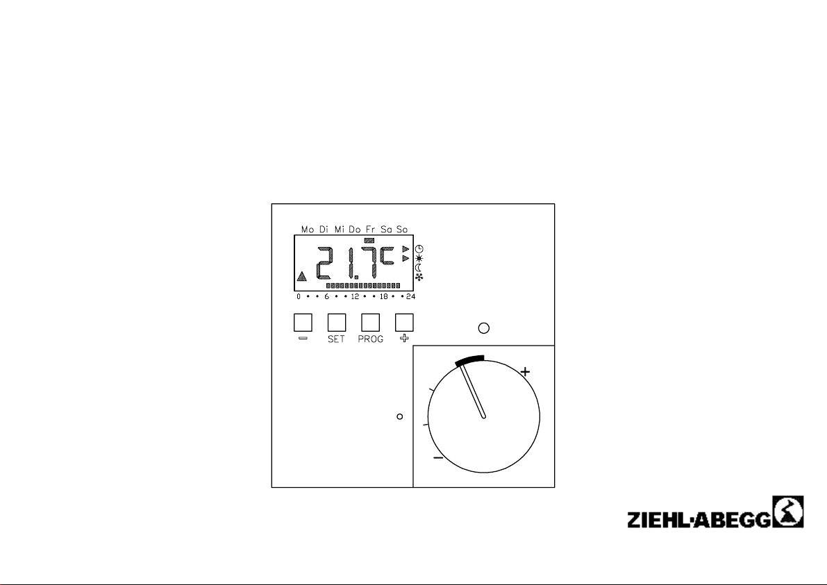
2. Controls and display ...................................................... 5
3. General function............................................................. 6
3.1 Setting the temperature .................................................. 6
3.2 Time program................................................................. 6
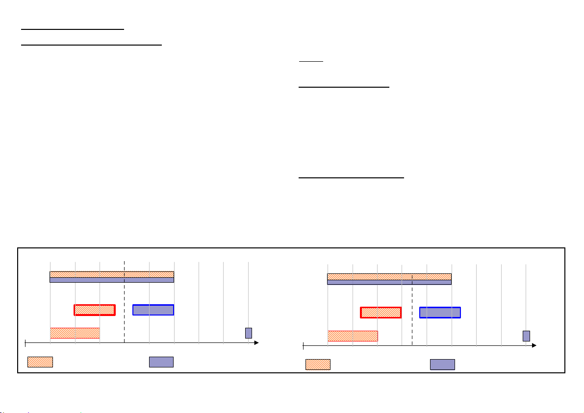
3.3 Control behavior............................................................. 6
4. Functions in the normal display..................................... 7
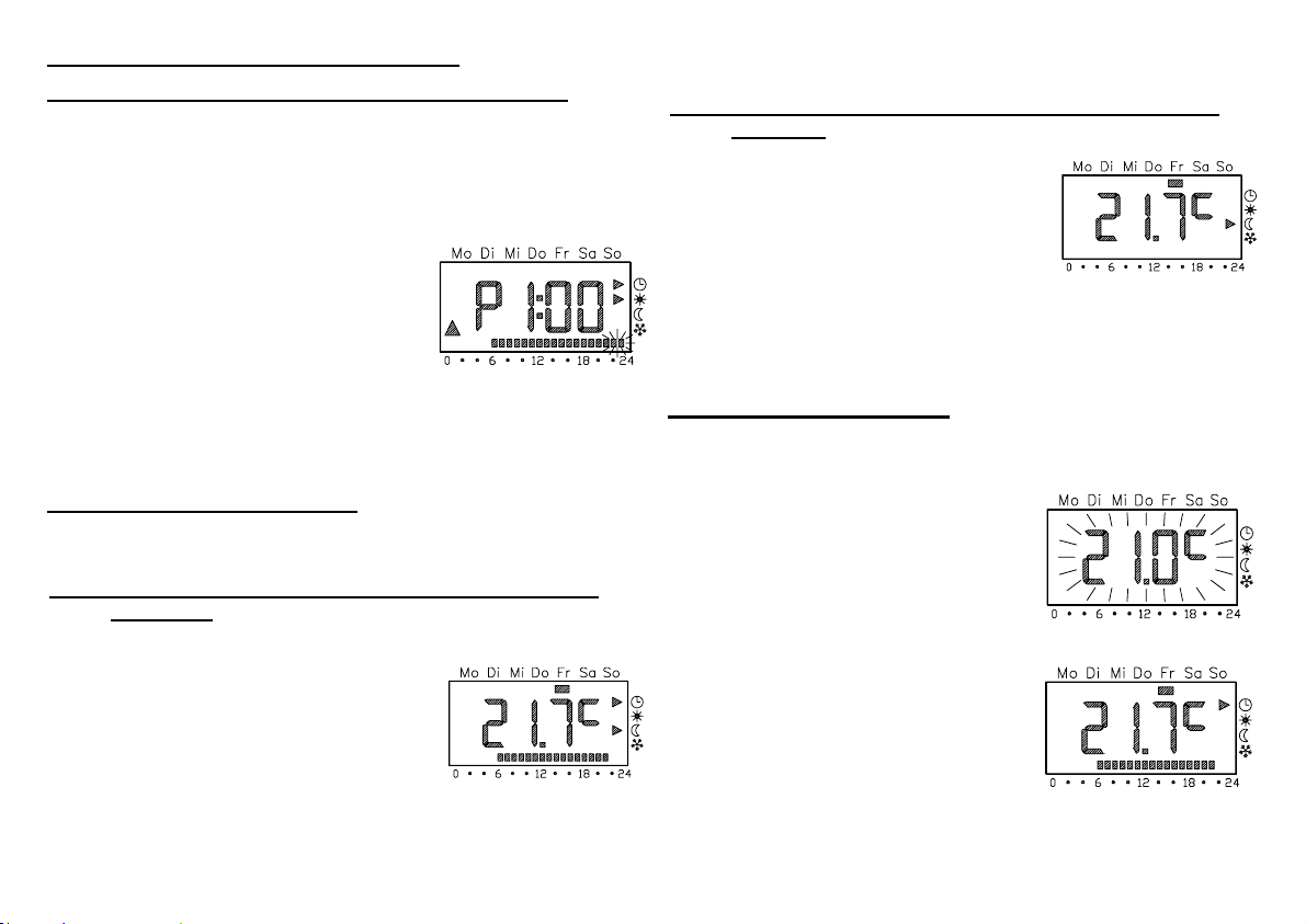
4.1 Party function (extend the heating phase) ....................... 7
4.2 Energy saving function ................................................... 7
4.3 Specific temperature....................................................... 7
4.4 Locking the keyboard...................................................... 8
4.5 Changing the operating mode ......................................... 8
5. Settings in the program menu........................................ 8
5.1 Setting the clock and date............................................... 8
5.2 Setting temperature levels – tEMP menu item ................. 9
5.3 Changing the time program – ProG menu item ................ 9
5.4 Vacation function...........................................................12
6. Failure causes and their rectification ...........................13
6.1 No display .....................................................................13
6.2 FAIL displayed ..............................................................13
6.3 –– –– displayed when a key is pressed ..........................13
6.4 Output is not triggered ...................................................13
Installation and commissioning guide ..............................14
7. Fields of application ..................................................... 14
8. Assembly and installation............................................. 14
8.1 Assembly...................................................................... 14
8.2 Assembly steps............................................................. 15
8.3 Connection diagram ...................................................... 15
8.4 Range limitation ............................................................ 16
9. Commissioning ............................................................. 16
10. Initial settings in the parameter menu ........................ 17
10.1 Software version (=).................................................... 18
10.2 Normal display (n)....................................................... 18
10.3 Operating mode (b) ..................................................... 18
10.4 Switching difference (d)............................................... 19
10.5 Frost-prevention temperature (F)................................. 19
10.6 Upper limit temperature (o).......................................... 19
10.7 Lower limit temperature (u).......................................... 19
10.8 Temperature at the external sensor (S)........................ 20
10.9 Minimum switching duration (t) .................................... 20
10.10 Sensor compensation (A) .......................................... 20
10.11 Initial heating optimization (E).................................... 20
10.12 Gradient of the initial heating optimization (r) ............. 21
10.13 Daylight saving change (U)........................................ 21
10.14 Running accuracy of the clock (G) ............................. 21
11. Reset (reset all settings) ............................................. 21
12. Technical data ............................................................. 23
Maintenance, Service........................................................ 24
Manufacturer reference, Service information................... 24
- 2 -
Contens
Chapter
Exclusion of liability............................................................ 3
Safety information ............................................................... 3
Transport, storage.............................................................. 4
1. General description ........................................................ 4
2. Controls and display ...................................................... 5
3. General function............................................................. 6
3.1 Setting the temperature .................................................. 6
3.2 Time program................................................................. 6
3.3 Control behavior............................................................. 6
4. Functions in the normal display..................................... 7
4.1 Party function (extend the heating phase) ....................... 7
4.2 Energy saving function ................................................... 7
4.3 Specific temperature....................................................... 7
4.4 Locking the keyboard...................................................... 8
4.5 Changing the operating mode ......................................... 8
5. Settings in the program menu........................................ 8
5.1 Setting the clock and date............................................... 8
5.2 Setting temperature levels – tEMP menu item ................. 9
5.3 Changing the time program – ProG menu item ................ 9
5.4 Vacation function...........................................................12
6. Failure causes and their rectification ...........................13
6.1 No display .....................................................................13
6.2 FAIL displayed ..............................................................13
6.3 –– –– displayed when a key is pressed ..........................13
6.4 Output is not triggered ...................................................13
Installation and commissioning guide ..............................14
7. Fields of application ..................................................... 14
8. Assembly and installation............................................. 14
8.1 Assembly...................................................................... 14
8.2 Assembly steps............................................................. 15
8.3 Connection diagram ...................................................... 15
8.4 Range limitation ............................................................ 16
9. Commissioning ............................................................. 16
10. Initial settings in the parameter menu ........................ 17
10.1 Software version (=).................................................... 18
10.2 Normal display (n)....................................................... 18
10.3 Operating mode (b) ..................................................... 18
10.4 Switching difference (d)............................................... 19
10.5 Frost-prevention temperature (F)................................. 19
10.6 Upper limit temperature (o).......................................... 19
10.7 Lower limit temperature (u).......................................... 19
10.8 Temperature at the external sensor (S)........................ 20
10.9 Minimum switching duration (t) .................................... 20
10.10 Sensor compensation (A) .......................................... 20
10.11 Initial heating optimization (E).................................... 20
10.12 Gradient of the initial heating optimization (r) ............. 21
10.13 Daylight saving change (U)........................................ 21
10.14 Running accuracy of the clock (G) ............................. 21
11. Reset (reset all settings) ............................................. 21
12. Technical data ............................................................. 23
Maintenance, Service........................................................ 24
Manufacturer reference, Service information................... 24
- 2 -