Zilmet intamix User manual

ZILMET USA
400 FRENCHTOWN ROAD
EAST GREENWICH, Rl 02818
T. (401) 884 4943
E. INFO@ZILMETUSA.COM
WWW.ZILMETUSA.COM
Installation and Maintenance Instructions
Instructions d’installation et entretien
Instrucciones de mantenimiento e instalación
THERMOSTATIC MIXING VALV E
ZTM7550G

1
Overview
The Zilmet Intamix Tank Maximiser kit is a Thermostatic Mixing Valve (TMV) including a Cold Water
connection, integral re-circulation port and a stainless steel corrugated flexible pipe for quick and
simple installation onto a water heater tank.
The Intamix Tank Maximiser controls the set mixed outlet temperature to the distribution of the system
from the tank by compensating for changes in both temperature and pressure of the incoming hot and
cold water supplies.
The Intamix Tank Maximiser also features tried and tested thermostatic anti-scald failsafe protection
for safety and peace of mind. In the event of a sudden drop of cold water pressure or complete failure
of the cold water supply the TMV will automatically shut-off preventing the risk of scalding.
Featuring a built in re-circulation port conveniently allows the installer to prevent waste hot water,
eliminating the need for extra plumbing connections.
The TMV is factory set to 120˚F and approved to ASSE1070 applications, featuring a patented
security system the valve can be manually adjusted by the installer and becomes approved for
ASSE1017 applications. The TMV application cannot be reverted back to ASSE1070 application
without the replacement of the patented security system.
The factory set mode must not be used as a point of use valve where ASSE1070 devices are required.
When used in the factory set mode the Intamix SinkSafe TMV must also be used on outlets for point of
use protection to ASSE1070.
Technical Specification ZTM7550G
Temperature range ASSE1070 95 to 120˚F (35 to 49˚C)
ASSE1017 95 to 140˚F (35 to 60˚C)
Factory set temperature 120˚F
Minimum flow rate to ensure
optimal performance 1.2 gpm (4.5 l/m)
Maximum inlet temperature 194˚F (90˚C)
Minimum inlet temperature 41˚F (5˚C)
Min ∆T between inlet and outlet 50˚F (10˚C)
Maximum inlet pressure static 150 psi (1034 kPa)
Maximum inlet pressure dynamic 75 psi (517 kPa)

2
Components
A Intamix Tank Maximiser (x1)
B Swivel Union Connector (x1)
C Cold Water Tee Connector (x1)
D Rubber Gasket - Not Shown in Assembly (1”x1 and ¾”x3)
E Temperature Gauge and Outlet Connector (x1) - ZTM07550G only
F Reversible Cold/Recirculation Connection inc check valve
and filter (x1 fitted)
G Reversible Port Plug (x1 fitted)
H ID Tag (x1)
I Corrugated Stainless Steel Hose (x1) - FNPT 17½” long
J Instruction Manual (x1)
K Security Clip
A
B
C
E
F
G
Hot Inlet
Mixed Water Outlet
Return
Water
Connection
I
K

3
Hydraulic Characteristics
Approvals
ASSE 1070 ASME A112.1070 & CSA B125.70 - 2015
ANSI/ASSE 1017-2009 & CSA B125.3
NSF/ANSI 372 - 2016 & NSF/ANSI 61-2017
Safety Instructions
Failure to follow instructions in the manual and local legislation may
result in a safety hazard or injury!
WARNING: This product can expose you to chemicals including lead,which is known to the
State of California to cause cancer and birth defects or reproductive harm.
For more information go to www.P65Warnings.ca.gov
0
5
10
15
20
25
30
35
40
45
50
0 2 4 6 8 10
12
Flow rate - gpm
Pressure - psi

4
Operation
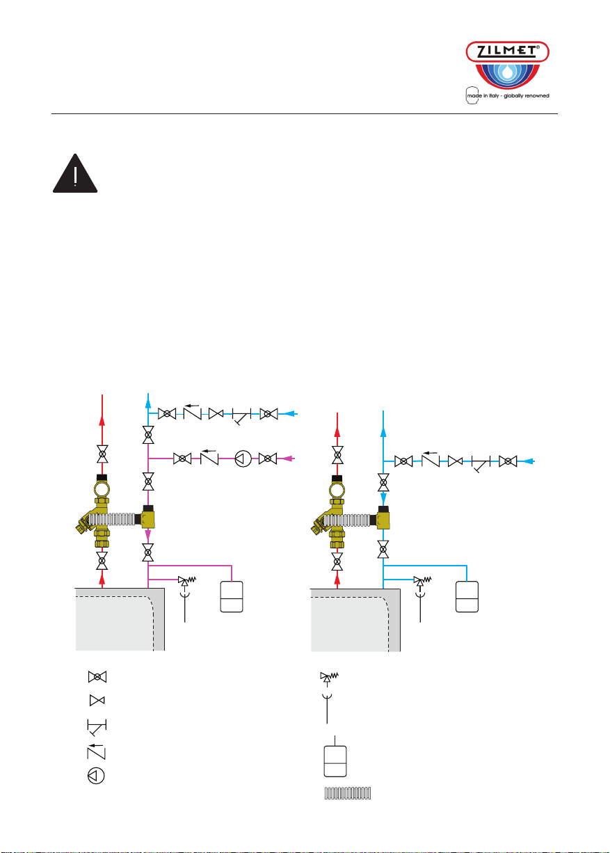
The Intamix Tank Maximiser consists of a TMV with a built-in recirculation port, a cold-water T
connection and a corrugated stainless-steel hose for easy, flexible and direct connection to the
¾” male NPT threaded top connections of most water heaters.
It also uniquely features a reversible cold water/recirculation inlet connection allowing for greater
installer flexibility and a neater finish.
The TMV mixes the hot and cold water supplies and delivers a constant set temperature from the
mixed water outlet.
The Intamix Tank Maximiser allows an increased usable hot water capacity from the water heater
tank by allowing the water to be stored at a higher temperature and safely distributed at a safer
temperature by mixing the cold water and effectively increases the usable hot water capacity
of the tank. Consequently the higher potential temperature of the hot water in the tank can reduce the
risk of legionella bacteria growth in the tank.
By increasing the water temperature of the tank it also reduces the risk of legionella growth
In the event of a cold water supply failure the TMV will automatically fail-safe and shut off the supply
of the mixed water. For the fail-safe function to be guaranteed there must be a minimum temperature
differential between the hot inlet water and the mixed outlet water of 50°F.
Installation
WARNING: This product and all associated work must be performed by qualified personnel
trained in the proper application, installation and maintenance of systems in accordance with
all applicable codes and ordinances.
WARNING: If this product is not installed, commissioned and maintained correctly according
to these instructions in this manual then it may not operate correctly and could endanger the
user.
WARNING: The system must be inspected to ensure that the operating conditions are within
the specification range of the Intamix Tank Maximiser before it is installed. Conditions outside
of the specification range will invalidate the warranty and prevent proper function of the
product.
Prior to installation, the system must be drained and flushed to remove any debris.
Appropriately sized filters must be installed at the inlet from the main water supply.
The Intamix Tank Maximiser must be installed by qualified personnel according to the diagrams in this
instruction manual and according to all applicable standards, codes and ordinances.
Consideration must be given to the water quality and if in excess of 10 grains of hardness then an
Activflo water condition is recommended to be fitted to assist in preventing excessive limescale.
For information on the ActivFlo please visit:
zilmetusa.com/installation-manuals-and-product-certifications
or scan the QR code opposite using your smart device.

5
Connecting the Swivel Union Connection (B) to the Water Heater Tank:
Ensure water is drained and isolated as instructed above.
Apply accredited sealing tape to the hot and cold connections on the
water heater tank.
Secure and tighten to the pipes from hot and cold outlets of the tank.
Connecting the TMV (A) to the Swivel Union Connection (B)
Position the Rubber Gasket (D) between the Swivel Connector (B) and the
TMV (A).
Tighten securely using the swivel nut.
Take care not to overtighten.
Consideration must be given to the alignment of the TMV for connection of
the hose.
Repeat the process for the Cold Water Tee (C).
Pipe from the water
heater tank
B
D
A

6
Connect the Cold Water Tee (c) to the Cold Water Inlet of the Tank
Connecting the Stainless Steel Hose (I) to the TMV (A) and the Cold Water Tee (C)
Connect the Flexible Hose (I) to the Cold Water/recirculation Port (F) of the TMV with the connection
of the Cold Water Tee (C).
WARNING: Make sure that all connecting pipework is watertight and free from leaks.
Ensure connections are not mechanically over stressed.
C
I
I
F
C
Cold water suppl
y
pipe/recirculation
Cold water feed
to the tank

7
Application Diagram
WARNING: To prevent any damage or loss of functionality to the TMV treat highly
aggressive water before it enters the TMV. Hardness must be less than 10 grains. Where
hardness is above 10 grains install a suitably sized ActivFlo water conditioner to the mains
inlet of the property to prevent limescale damage.
Zilmet shall not be liable for any damages resulting from stress corrosion, misapplication, misuse,
improper installation, or inappropriate maintenance of any of its products.
The Intamix Tank Maximiser can be installed with a recirculation line to allow the returned mixed
water from the system to be connected directly back into the connection Tee (C).
Installations must include a thermal expansion vessel installed after the non-return valve on the cold
water supply prior to entering the water heater.
Note: the diagrams below are for guidance only.
All installations must be undertaken by qualified personnel and according to all applicable standards,
codes, and ordinances.
TANK
System With Recirculation System Without Recirculation
Isolating valve
Pressure reducing valve
Strainer
Non return valve
Pump
Tundish
Expansion Vessel
Flexible tube
CC
Mains water supply
Mains water supply
Re-circulation
TANK
Temperature & pressure relief valve

8
Commissioning
WARNING: Water temperatures in excess of 100°F (38°C) can be dangerous. During
installation, commissioning and or maintenance of the TMV necessary precautions and due
care must be taken to ensure people are not endangered.
After installation, the valve must be tested and commissioned in accordance with the instructions given
below, taking into account current applicable codes and standards.
1. Ensure that the system is clean and free from any dirt or debris before commissioning the
thermostatic mixer.
2. It is recommended that the temperature is set using a suitable calibrated digital thermometer.
The valve must be commissioned by measuring the temperature of the mixed water emerging at the
point of use.
3. The maximum discharge temperature from the valve must be set taking account of the fluctuations
due to simultaneous use. It is essential for these conditions to be stabilized before commissioning.
4. Adjust the temperature using the adjusting screw on the valve.
The Zilmet Intamix Tank Maximiser is provided with a locking ring conforming to ASSE1070.
Setting the Temperature/Commissioning
WARNING: The Intamix Tank Maximiser is not designed in its factory set mode of
ASSE1070 for mixing water at fixtures as a point of use valve. The ASSE1070 approved
Intamix SinkSafe TMV must be used wherever a scald protection device is required.
NOTE: The Intamix Tank Maximiser is certified to both ASSE 1017 and ASSE1070. It is factory
pre-set to 120˚F according to ASSE 1070. The temperature of valve can be increased according to
ASSE 1017 by removing the security clip.
The Intamix Tank Maximiser is factory set to 120°F (49°C) according to designation ASSE1070.
However the temperature can be adjusted using a hex key according to the + or – indication marking
on the TMV body.
Security clip
Hexagon for
Allen key
adjustment

9
1 Insert the Allen key into the temperature adjustment rod and unscrew the locking nut with a wrench
without removing the Allen key.
2 Adjust the temperature rod with the Allen key.
3 Re-tighten the locking ring nut with a wrench without removing the Allen key.
Allow the mixed outlet temperature to stabilize for 60 seconds and once again take a temperature
reading. Repeat the procedure until the desired temperature has been reached.
Check that the outlet temperature is stable over a full range of flow rates and that the flow rate is
adequate for the application.
Records must be maintained of all checks and adjustments made.
Maintenance
Performance tests should be carried out regularly to monitor the performance of the TMV.
Any deterioration of performance could indicate that maintenance may be required to the TMV or
system.
If there is a significant change from the previous test result in the mixed outlet temperature of the
water from the TMV then maintenance should be conducted according to Troubleshooting below.
Setting the Temperature/Commissioning
To adjust the valve over 120°F (49°C) the security clip (depicted below) would need to be removed
and would no longer be approved for ASSE1070 application.
The security clip can be removed by hand.
By removing the security clip it will break and can not be reused.
Adjust the temperature using the adjusting screw on the valve.
Step 1 Step 2 Step 3
Hexagon
for wrench

10
TroubleShooting
Problem Cause Solution
Required mixed water
temperature cannot be
achieved
i) supply temperature or
pressures out of specification
parameters
ii) hot and cold supplies are in
reverse
iii) low flow rate
iv) strainer/filter is blocked
i) ensure supply conditions are
within the limits of the valve
ii) refit the TMV in the correct
orientation
iii) increase the flow rate
iv) clean or replace the
strainer/filter
Fluctuating mixed water
temperature i) fluctuating supply
temperatures or pressures
ii) strainer/filter is blocked
iii) TMV not commissioned
correctly
i) set inlet conditions according
to the specification of the TMV
ii) clean or replace the
strainer/filter
iii) recommission the TMV
according to instructions
No flow or low flow
from the TMV i) hot or cold water supply
failure
ii) strainer/filter is blocked
iii) supply pressures outside
specification of the TMV
iv) debris obstructing the func-
tion of the TMV
i) restore supply and
re-commission mixed water
outlet temperature
ii) clean or replace the
strainer/filter
iii) restore supply and
re-commission mixed outlet
temperature
iv) clean debris from TMV
Valve is noisy or
vibrating i) excessive flow velocity
ii) valve sized incorrectly
i) reduce flow velocity or fit an
appropriate pressure reducing
valve
ii) check valve specification
against use
Thermal shut-off not
operating i) TMV not installed correctly
ii) minimum temperature
differential not achieved
iii) TMV mechanism is blocked
by debris or scale
i) refit the TMV correctly
according to these instructions
ii) increase the hot water
temperature within limits
iii) clean debris from TMV
Cross flow with hot
water into the cold and
vice versa
i) non-return valves are
blocked i) check operation of non-
return valves and clean or
replace

11
Spares/Accessories
Intamix Tank Maximiser
Item Code - ZTM7500
Temperature Gauge and
Outlet Connection
Item Code - ZTG757520
Swivel Union Connector
Item Code - ZTMSPR1XX
Cold Water Tee Connection
Item Code - ZTMSPR3XX Reversible Connection
inc. Check Valve
Item Code - ZTMSPR2XX
Plug for Reversible Port
Item Code - ZTMSPR4XX
Rubber Gaskets
1”x1 Item Code - ZTMSPR5XX
¾”x 3 Item Code - ZTMSPR6XX
Corrugated Stainless Steel Hose
Item Code - HOSE457

12
Warranty
This warranty cannot be transferred – it is extended only to the original purchaser or first user
of the product. By accepting and keeping this product you agree to all of the warranty terms
and limitations of liability described below. The warranty is not valid if the purchaser does
not follow the terms of payment agreed to with ZILMET.
IMPORTANT WARNING - READ CAREFULLY THE INSTALLATION, OPERATING
AND MAINTENANCE INSTRUCTIONS MANUAL (“MANUAL”) to avoid serious
personal injury and/or property damage and to ensure the safe use and proper care of this
product.
Who Receives Zilmet’s Product Warranty: all purchasers or first user of the new
product; the warranty is non-transferable.
What Is Covered By This Warranty: ZILMET warrants to the purchaser or first user of
the new product that, at the time of manufacture, the product is free from defects in material
and workmanship. Any warranty claim must be made within five (5) years, unless another
time period is agreed between ZILMET and the purchaser, measured from the time the
product was manufactured.
What Zilmet Will Do If You Have A Covered Warranty Claim: in the event of a
breach of the foregoing warranty, ZILMET will, at its option, either make repairs to correct
any defect in material or workmanship or supply and ship either new or used replacement
parts or products. ZILMET will not accept any claims for labor, property damage or other
costs.
What This Warranty Does Not Cover - Exclusions And Limitations: this warranty
does not cover any claim unless it was caused by a defect in material or workmanship during
the warranty period. In addition, this warranty shall not apply:
•if the product is not correctly installed, operated and maintained as described in the
manual provided with this warranty.
•to any failure or malfunction resulting from abuse (including freezing); improper or
negligent: handling, shipping (by anyone other than ZILMET), storage, use, operation,
accident; or alteration, lightning, flood or any other environmental condition.
•to any failure or problem resulting from the use of the product for any purpose other than
those specified in the accompanying manual or alteration of any part of the product.
•this warranty does not cover labor costs, shipping charges, service charges, delivery
expenses, administrative fees or any costs incurred in removing or reinstalling the
product.
•this warranty does not cover any claims submitted to ZILMET or a ZILMET-authorized
distributor or retailer more than 15 days after expiration of the applicable warranty time
period described in this warranty.
•this warranty does not cover repair or replacement costs not authorized in advance by
ZILMET.
•this warranty also does not cover corrosion on mild steel flanges (stainless steel flanges
must be used).

13
Waranty
THESE WARRANTIES ARE GIVEN IN LIEU OF ALL OTHER EXPRESS WARRANTIES.
NO ZILMET REPRESENTATIVE OR ANY OTHER PARTY IS AUTHORIZED TO
MAKE ANY WARRANTY OTHER THAN THOSE EXPRESSLY CONTAINED IN THIS
WARRANTY AGREEMENT.
Additional Warranty Limitations: ALL IMPLIED WARRANTIES, INCLUDING THE
IMPLIED WARRANTIES OF MERCHANTABILITY AND FITNESS FOR A PARTICULAR PURPOSE
ARE SPECIFICALLY DISCLAIMED. Some states do not allow limitations on how long an
implied Warranty lasts, so the above limitation may not apply to you.
Limitations Of Remedies: THE REMEDIES CONTAINED IN THIS WARRANTY ARE
THE PURCHASER’S / FIRST USER’S EXCLUSIVE REMEDIES. IN NO CIRCUMSTANCES
WILL ZILMET BE LIABLE FOR MORE THAN, AND PURCHASER / FIRST USER’S REMEDIES
SHALL NOT EXCEED, THE PRICE PAID FOR THE PRODUCT. IN NO CASE SHALL ZILMET
BE LIABLE FOR ANY SPECIAL, INDIRECT, INCIDENTAL OR CONSEQUENTIAL DAMAGES,
WHETHER RESULTING FROM NON-DELIVERY OR FROM THE USE, MISUSE, OR INABILITY
TO USE THE PRODUCT OR FROM DEFECTS IN THE PRODUCT OR FROM ZILMET’S OWN
NEGLIGENCE OR OTHER TORT
This exclusion applies regardless of whether such damages are sought for breach of
warranty, breach of contract, negligence, strict liability, in tort or under any other legal
theory. Such damages include, but are not limited to, inconvenience, loss or damage to
property, mold, loss of profits, loss of savings or revenue, loss of use of the products or
any associated equipment, facilities, buildings or services, downtime, and the claims of
third parties including customers. Some states do not allow the limitation of incidental or
consequential damages, so the above limitation or exclusion may not apply to you.
What To Do If You Have A Problem Covered By This Warranty: any covered
warranty service must be authorized by ZILMET.
Contact the person from whom you purchased the product, who must receive a written
authorization from a ZILMET distributor or from ZILMET. The following documentation must be
supplied in order to receive authorization:
•The “Schedule of returns” sheet duly filled by the purchaser / first user.
•Reports, photos etc. describing the problem. If you do not receive a prompt response,
call ZILMET directly at 401-884-4943. Notice of a warranty claim should be submitted
by the authorized distributor to ZILMET at the following address shown in these
instructions.
Before ZILMET decides to provide any replacement part or product, it may, as a pre-condition
to making such a determination, require that the warranty claimant ship the product, postage
prepaid to an authorized ZILMET distributor or to ZILMET and provide proof of purchase
evidenced by the original sales receipt.
Replacement Product Warranty: in case of replacement of a product or any
component part, ZILMET reserves the right to make changes in the design, construction,
or material of the substitute components or products, which shall be subject to all of the
terms and limitation of this warranty except that the applicable warranty periods shall be
reduced by the amount of time the warranty claimant owned the product prior to submitting
notification of the warranty claim.

14
Notes:

15
Aperçu général
Le kit Zilmet Intamix Tank Maximiser est un mitigeur thermostatique (TMV pour Thermostatic Mixing
Valve en anglais) qui comprend un raccordement à l’eau froide, un orifice de recirculation intégré et
un flexible ondulé en acier inoxydable, pour l’installer rapidement et facilement sur un chauffe-eau.
Intamix Tank Maximiser contrôle la consigne de température mélangée à la sortie de distribution
du système, à partir du réservoir, en compensant les changements de température et de pression des
alimentations d’eau chaude et froide entrantes.
Intamix Tank Maximiser dispose également d’une protection thermostatique anti-brûlure, à sécurité
intégrée éprouvée, pour garantir sécurité et tranquillité d’esprit. En cas de chute soudaine
de la pression d’eau froide ou de panne complète de l’alimentation en eau, le mitigeur thermostatique
s’arrêtera automatiquement pour éviter le risque de brûlure.
Doté d’un port de recirculation intégré, il permet à l’installateur d’éviter le gaspillage d’eau chaude,
éliminant ainsi le besoin de raccorder des plomberies supplémentaires.
Le mitigeur thermostatique est réglé en usine à 120 °F et approuvé pour les applications ASSE1070.
Avec son système de sécurité breveté, le robinet peut être ajusté manuellement par l’installateur et
convenir également pour les applications ASSE1017. L’application du mitigeur ne pourra pas être
reconvertie en application ASSE1070 sauf en remplaçant le système de sécurité breveté.
Le mode réglé en usine ne doit pas être utilisé comme vanne de point d’utilisation lorsque des
appareils ASSE1070 sont nécessaires. Lorsqu’il est utilisé dans le mode réglé en usine, le mitigeur
thermostatique Intamix SinkSafe doit également être utilisé sur les prises pour la protection du point
d’utilisation de l’ASSE1070.
Caractéristiques techniques
Plage de température ASSE1070 95 à 120˚F (35 à 49˚C)
ASSE1017 95 à 140˚F (35 à 60˚C)
Température réglée en usine 120˚F
Débit minimal pour la meilleure
performance 1.2 gpm (4.5 l/m)
Température d’entrée maximale 194˚F (90˚C)
Température d’entrée minimale 41˚F (5˚C)
Min ∆T entre entrée et sortie 50˚F (10˚C)
Pression d’entrée maximale statique 150 psi (1034 kPa)
Pression d’entrée maximale dynamique 75 psi (517 kPa)

16
Composants
A Intamix Tank Maximiser (x1)
B Raccord orientable (x1)
C Raccord en T d’eau froide (x1)
D Joint en caoutchouc – Non visible (1” x1 et 3/4” x3)
E Raccord de sortie avec indicateur de température (x1) - ZTM07550G uniquement
F Raccord réversible froid/recirculation avec clapet anti-retour et filtre (x1 monté)
G Prise à orifice réversible (x1 monté)
H Étiquette d’identification (x1)
I Tuyau ondulé en acier inoxydable (x1) – FNPT 17 1/2” de long Tuyau flexible tressé (x1) –
FNPT 17 1/2” de long
J Mode d’emploi (x1)
A
B
C
E
F
G
Entrée d’eau chaude
ortie d’eau mitigée
Raccord
d’eau de
retour
I

17
Caractéristiques hydrauliques
Homologations
ASSE 1070 ASME A112.1070 et CSA B125.70 – 2015
ANSI/ASSE 1017-2009 et CSA B125.3
NSF/ANSI 372 – 2016 et NSF/ANSI 61-2017
Consignes de sécurité
Le non-respect des instructions du manuel et de la législation locale peut
entraîner un risque pour la sécurité ou des blessures!
MISE EN GARDE: Ce produit peut entraîner l’exposition à des substances chimiques,
comme le plomb, qui est connu dans l’État de Californie pour provoquer le cancer et des
anomalies congénitales ou des troubles de la reproduction.
0
5
10
15
20
25
30
35
40
45
50
0 2 4 6 8 10
12
Débit - gpm
Pression - psi

18
Fonctionnement
Intamix Tank Maximiser se compose d’un mitigeur thermostatique avec un orifice de recirculation
intégré, un raccord en T d’eau froide et un tuyau ondulé en acier inoxydable pour le raccorder
facilement, de manière flexible et directe aux raccords supérieurs filetés NPT mâles de ¾” de
la plupart des chauffe-eau.
Il comprend également la caractéristique unique d’un raccord d’entrée d’eau froide/recirculation
réversible, permettant une plus grande flexibilité pour l’installateur et une finition plus soignée.
Le mitigeur thermostatique mélange l’eau chaude et froide à l’entrée et délivre une température de
consigne constante depuis la sortie d’eau mitigée.
Intamix Tank Maximiser permet d’augmenter la capacité d’eau chaude utilisable du chauffe-eau en
assurant le stockage de l’eau à une température plus élevée et sa distribution en toute sécurité à une
température sans danger, en mélangeant l’eau froide et augmentant efficacement la capacité d’eau
chaude utilisable du réservoir. Par conséquent, la température potentielle plus élevée de l’eau chaude
dans le réservoir peut réduire le risque de croissance des bactéries légionelles à l’intérieur.
L’augmentation de la température de l’eau du réservoir réduit également le risque de croissance de
légionelles.
En cas de panne d’alimentation en eau froide, le mélangeur thermostatique sera automatiquement
sécurisé et coupera l’alimentation en eau mitigée. Pour que la fonction de sécurité intégrée
soit garantie, il doit y avoir une différence de température minimale entre l’eau chaude d’entrée et
l’eau de sortie mitigée de 50 °F.
Installation
MISE EN GARDE: Ce produit et tous les travaux associés doivent être exécutés par
un personnel formé à l’application, installation et entretien appropriés des systèmes
conformément à toutes les lois et ordonnances applicables.
MISE EN GARDE: Si ce produit n’est pas installé, mis en service et entretenu correctement,
conformément aux instructions de ce manuel, il risque de ne pas fonctionner correctement et
de mettre l’utilisateur en danger.
MISE EN GARDE: : Le système doit être inspecté pour s’assurer que les conditions de
fonctionnement rentrent dans les limites techniques d’Intamix Tank Maximiser avant son
installation. Des conditions en dehors de ces limites entraîneront la déchéance de la garantie
et empêcheront le bon fonctionnement du produit. Prior to installation, the system must be
Avant l’installation, le système doit être vidangé et rincé pour éliminer les débris. Des filtres de taille
appropriée doivent être installés à l’entrée de l’alimentation principale en eau.
Intamix Tank Maximiser doit être installé par un personnel qualifié sur la base des schémas de ce
mode d’emploi et conformément à toutes les normes, lois et ordonnances applicables.
Tenir compte de la qualité de l’eau et si elle dépasse 10 gpg, il
est recommandé d’installer un système de traitement de l’eau Activflo pour aider à
prévenir l’excès de calcaire.
Pour plus d’informations sur ActivFlo, prière de visiter:
zilmetusa.com/installation-manuals-and-product-certifications ou numériser le
code QR ci-contre avec un smartphone.

19
Branchement du raccord orientable (B) au chauffe-eau:
Ensure water is drained and isolated as instructed above.
Apply accredited sealing tape to the hot and cold connections on the
water heater tank.
Secure and tighten to the pipes from hot and cold outlets of the tank.
Connecting the TMV (A) to the Swivel Union Connection (B)
Mettre le joint en caoutchouc (D) entre le raccord orientable (B) et le mitigeur
(A)
Serrer fermement à l’aide de l’écrou orientable.
Veiller à ne pas trop serrer.
Veiller également à l’alignement du mitigeur thermostatique pour le
raccordement du tuyau.
Répéter le processus pour le raccord en T d’eau froide (C).
Branchement du raccord de sortie/indicateur de température (E) à la sortie d’eau mit-
igée du mitigeur thermostatique (A) -- Uniquement modèles Tank Maximiser Pro.
Disponible en option sous le code ZTG 757520
Mettre le joint en caoutchouc (D) entre la sortie d’eau mitigée du mitigeur
(A) et le raccord de sortie (E).
Serrer fermement à l’aide de l’écrou orientable.
Veiller à ne pas trop serrer.
Veiller également à l’alignement de l’indicateur de température.
E
D
A
B
D
A
Tuyau sort
ant du
chauffe-eau
This manual suits for next models
1
Table of contents
Languages:
Popular Plumbing Product manuals by other brands

Hans Grohe
Hans Grohe Fixfit Square 26455 3 Series Instructions for use/assembly instructions

Moen
Moen Chateau TL183BC Specifications

Elkay
Elkay DRKRQ2822 Specifications

Franke
Franke SIRIUS CA210/2N Installation and operating instructions

Laufen
Laufen Solution 2.9844.1 manual

Kohler
Kohler K-110 installation guide

tissino
tissino Giorgio Series installation manual

Glacier bay
Glacier bay 873W-3201 Use and care guide

Dimplex
Dimplex SVT 200KV Installation and operating instructions

SFA
SFA Saniflo Sanicubic 2 Troubleshooting Quick Guide

DURAVIT
DURAVIT P3 Comforts 720151 Mounting instructions

Grohe
Grohe Essence New 19976001 manual