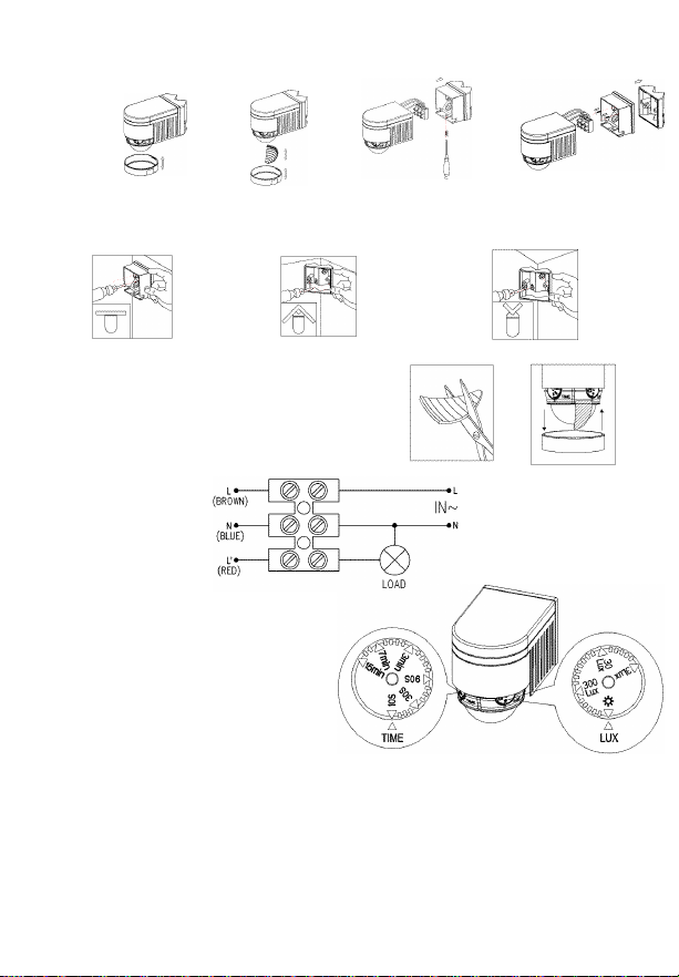
Fix the bottom on the selected position with the inflated screw.
Fix the sensor at the bottom and tighten the screw. Switch onthe power and then you can
test it.
OR
Figure1 Figure2 Figure3
It not only can install on the wall directly but also can install in the inner corner or outer
corner with the help of the widget (refer to photograph below):
Flat mounted Inner corner mounted Outer corner mounted
Note: you can cut the plastic cover whatever
shape you want and make different detection
range. (refer to right figure)
CONNECTION-WIRE DIAGRAM:
(See the right figure)
TEST:
Turn the TIME knob anti-clockwise on
the minimum (10s). Turn the LUX
knob clockwise on the maximum
(sun).
Switch on the power; the sensor and
its connected lamp will have no signal
at the beginning. After Warm-up
30sec, the sensor can start work .If the sensor receives the induction signal, the lamp will
turn on. While there is no another induction signal any more, the load should stop working
within 10sec±3sec and the lamp would turn off.
Turn LUX knob anti-clockwise on the minimum (3LUX). If the ambient light is more than
3LUX, the sensor would not work and the lamp stop working too. If the ambient light is less
than 3LUX (darkness), the sensor would work. Under no induction signal condition, the
sensor should stop working within 10sec±3sec.
Note: when testing in daylight, please turn LUX knob to (sun) position, otherwise
the sensor could not work!
Troubleshooting:
The load does not work:
a. Please check if the connection of power source and load is correct.
b. Please check if the load is good.
c. Please check if the settings of working light correspond to ambient light.
The sensitivity is poor:
a. Please check if there is any hindrance in front of the detector to affect it to receive
the signals.
b. Please check if the ambient temperature is too high.
c. Please check if the induction signal source is in the detection field.
d. Please check if the installation height corresponds to the height required in the
instruction.
e. Please check if the moving orientation is correct.
The sensor can not shut off the load automatically:
a. Please check if there is continual signal in the detection field.
b. Please check if the time delay is set to the maximum position
c. Please check if the power corresponds to the instruction.
Helpline
If you receive this item with parts broken or missing, please telephone:
0845-230-3400
Please have ready your name, address, tel. no., product reference, where purchased
and parts required. An answering service is in operation outside office hours and during busy
periods.
We regret that we are unable to give advice on internal house wiring.
Cascade Holdings Ltd, Gorse Mill, Gorse Street, Chadderton, Oldham. OL9 9RJ