Zip Water Zip HydroTap G4 BCS100/75 User manual

802265 v3.05 09.20 HT BCS Compact Commercial Instructions Page 1 of 32
Affix Model Number Label
Here
802265
BCS Compact models
Installation and Operating Instructions
Zip HydroTap G4
®

Page 2 of 32 802265 v3.05 09.20 HT BCS Compact Commercial Instructions
Tap Options
The Zip HydroTap G4 appliance series offers a range of interchangeable taps to suit the customer’s needs.
For ease of installation, it is recommended to fit the tap before installing the undersink Command Centre.
The installation procedure for each of the taps is detailed in separate tap installations, supplied with the tap.
For all operational features of the HydroTap, please refer to the User Guide.
These taps are directly compatible with the HydroTap G4
Command Centre.
Arc / Cube Tap
Classic Tap
Elite Tap
The Mixer tap range is an additional series of taps that
may be used in conjunction with any one of the taps
shown above, to create 4-in-1 models
Arc / Cube Mixer
The All-In-One Tap is a stand alone tap that may be used
as an alternative to any of the above combinations.
Classic All-In-One Celsius All-In-One

802265 v3.05 09.20 HT BCS Compact Commercial Instructions Page 3 of 32
HydroTap Specifications
Installation Checklist .................................................................................................................... 4
General Product Features............................................................................................................ 5
Important Safety Instructions ....................................................................................................... 6
Warnings and Regulatory Information.......................................................................................... 7
Major Components and Accessories ........................................................................................... 8
Technical Specifications............................................................................................................... 9
Before Installation and Site Requirements................................................................................... 9-10
Installation procedure:
STEP 1 -
Fit the tap to the benchtop or sink, before installing the Command Centre.
(Refer to the Tap installation instructions, supplied with the Tap)
STEP 2 - Check for adequate ventilation
Section 2 - Ventilation
2.1 - Cut out details.......................................................................................................... 11-13
STEP 3
- Install the Booster Heater (if required)
Section 3 - Booster Heater
3.1 - Booster Heater specifications and installation .......................................................... 14-16
STEP 4 -
Fit the CO2Gas cylinder
Section 4 - CO2Cylinder
4.1 - Connect and secure the 2.64kg CO2gas cylinder .................................................... 17-18
STEP 5
- Install the Command Centre
Section 5 - Command Centre installation
5.1 - External bypass valve............................................................................................... 19
5.2 - Hose and tube fitting................................................................................................. 19
5.3 - John Guest fittings .................................................................................................... 20
5.4 - Carbonation valve..................................................................................................... 20
5.5 - Model BCS 100/75.................................................................................................... 21
5.6 - Model BCSHA 100/75 - AIO Mains........................................................................... 22
5.7 - Model BCSHAV 100/75 - AIO Vented....................................................................... 23
5.8 - Model BCSHA 140/75 - 5-in-1 Vented...................................................................... 24
STEP 6
- Commission the HydroTap
Section 6 - Commissioning
6.1 - CO2Purge................................................................................................................. 25
6.2 - Filter Flush ................................................................................................................ 25
6.3 - Boiling Calibration..................................................................................................... 26
6.4 - Booster...................................................................................................................... 26
6.5 - Sensor Calibration .................................................................................................... 27
6.6 - Command Centre Flush............................................................................................ 2/
6.7 - Carbonation Valve Flow Adjustment......................................................................... 28
Troubleshooting Table ................................................................................................................. 29
End of Life Disposal ..................................................................................................................... 30
Contact Details............................................................................................................................. 32
Index

Page 4 of 32 802265 v3.05 09.20 HT BCS Compact Commercial Instructions
Before Installation:
A. Read the instructions and check if there is adequate space to mount all of the components.
B. Note: Not all fittings are supplied with the appliance kit. Isolation valves are not supplied.
C. Check the mains water pressure is between 300 - 700kPa
D. Check the water quality to determine if extra filtration will be required.
NOTE: This product must be fitted to a potable water supply
E. Check the appliance rating plate and ensure correct power is available for the appliance.
F. Check the under counter cupboard supporting the appliance is adequate for
the total weight of the appliance, when full of water.
Before Commissioning:
1. Check the unit has been installed correctly.
2. Check all plumbing fittings have been tightened.
3. Ensure the outlet and vent pipes are positioned to drain correctly.
4. Ensure there is adequate ventilation.
5. Check all tubes from the Command Centre to the tap, have a constant rise and there are no
sags or kinks in the hoses.
6. Check all electrical connections are correct and there are no loose wires.
Commission: (See section 6)
7. Flush the supply line before connecting.
8. Turn on the water and check for leaks.
9. Flush the filters (this commences auto calibration for Boiling models)
10. Activate / enable the Booster (if fitted)
11. Purge the CO2
12. Calibrate the safety sensor (for Boiling models)
13. Where applicable, program the unit to suit the customer’s requirements.
Installation Checklist

802265 v3.05 09.20 HT BCS Compact Commercial Instructions Page 5 of 32
Thank you for purchasing a Zip HydroTap. Please read and follow these instructions carefully to ensure safe
and trouble free service. If service is required, please contact your Zip Service Provider.
What is the Zip HydroTap ?
The Zip HydroTaps are electronically controlled, filtered, Boiling, Chilled and Sparkling water, drinking
systems for kitchens and tea rooms. The HydroTap units are under bench drinking water appliances with a
dispensing tap mounted on a sink or bench, which may be used for residential or commercial applications.
These units utilise a conventional refrigerant compressor to chill the water and (for BCS) an immersion
heating element to boil the water and all utilise a CO2gas cylinder to carbonate the chilled water. Depending
on the model, these units will dispense boiling water (factory set to 98°C) chilled water (factory set to 3-5°C)
These units are NOT designed to be used for sanitary fixtures.
The boiling water units are fitted with a tap mounted, child safety lock. In addition, there are various energy
saving options accessible via the main menu. Each boiling unit is equipped with a self-calibrating program
which caters for altitude adjustment. The 2.64kg CO2bottle is refillable and should be returned to your
nearest HydroTap agency for exchange, whereas the water filter is a disposable item. Both will require
periodic replacement and are covered by a limited OEM warranty.
It is important that the Installation be done safely, correctly and completely, in order to utilise all the benefits
the HydroTap can provide. Each unit can be ordered with the Tap Head Assembly for Disabled use. The
disabled levers are supplied with Braille caps for the visually impaired.
General Product Features
HydroTap BCS Compact
ON-OFF Switch
Command centre
Din plug
(for accessories)
IEC Socket

Page 6 of 32 802265 v3.05 09.20 HT BCS Compact Commercial Instructions
Important Safety Instructions
This manual contains important safety and installation instructions for the Zip HydroTap G4.
Safety
This appliance is not intended for use by persons (including children) with reduced physical, sensory or
mental capabilities, or lack of experience and knowledge, unless they have been given supervision or
instruction concerning use of the appliance by a person responsible for their safety. Children should be
supervised to ensure that they do not play with the appliance.
For products sold in Europe, this appliance can be used by children aged from 8 years and above and
persons with reduced physical, sensory or mental capabilities or lack of experience and knowledge if they
have been given supervision or instruction concerning use of the appliance in a safe way and understand
the hazards involved. Children shall not play with the appliance. Cleaning and user maintenance shall not be
made by children without supervision.
Refrigerant
The Zip HydroTap unit contains R134A refrigerant under pressure. Maintenance of the refrigeration unit must
be carried out by an accredited service provider or qualified refrigeration technician.
Qualifications
If the power cable is damaged it must be repaired only by a qualified technician. To avoid hazards, all
Installation procedures must be carried out by a suitably qualified tradesperson. The power cable and power
outlet must be in a safe visible position for connection.
Venting
Sometimes steam and / or condensed droplets may discharge through a vent outlet at the tap. If the tap is not
installed using the Font pedestal, ensure the tap body is located so the tap outlet safely dispenses into the
sink bowl area.
Lifting
Take care when lifting the Zip HydroTap unit. Some units may exceed safe lifting limits. If you feel this is
beyond your personal capabilities, please seek assistance with the lift. The weights of the units are marked
on the packaging. Do not lift the unit by the front cover or any connections at the top rear of the unit. Refer to
section 1.2 technical specification for the weight of your product.
Airflow
The ambient temperatures, when installed in a cupboard, must be between 5ºC - 35ºC. Proper air circulation
must be provided. The system will operate satisfactorily only if the recommended air gaps of 50mm on each
side are provided. See section 2 for correct installation details
Altitude
Water boils at varying temperatures at different altitudes. Your HydroTap adjusts for this during startup
calibration and will recalibrate itself on a regular basis.
Frost Protection
If this appliance is located where the ambient air temperature could fall below 5ºC when the heater is not
in use, do not turn off the appliance electrically. This safeguard does not offer the same protection to the
connecting pipework and fittings.ed
Positioning
It is important to ensure the Command Centre is positioned in an accessible area close to the floor level. The
unit must have its base mounted in a horizontal position with all inlets and outlets facing up. The Tap must be
located above the Command Centre.

802265 v3.05 09.20 HT BCS Compact Commercial Instructions Page 7 of 32
Important Safety Instructions
!
WARNINGS
1. The Zip HydroTap unit must be earthed. The resistance of the earth
connection from each exposed metal part must be less than 1 ohm.
2. All Installation and service work must be completed by trained and suitably
qualified Tradespeople. Faulty operation due to unqualified persons working
on this product, or any other Zip product may void warranty coverage.
3. Plumbing and electrical connections must be made in accordance with local
regulations and relevant standards. In Australia and New Zealand: Plumbing
standard AS/NZS 3500 & Electrical Wiring Rules AS/NZS 3000.
4. This HydroTap product is rated for 230V 50Hz AC operation.
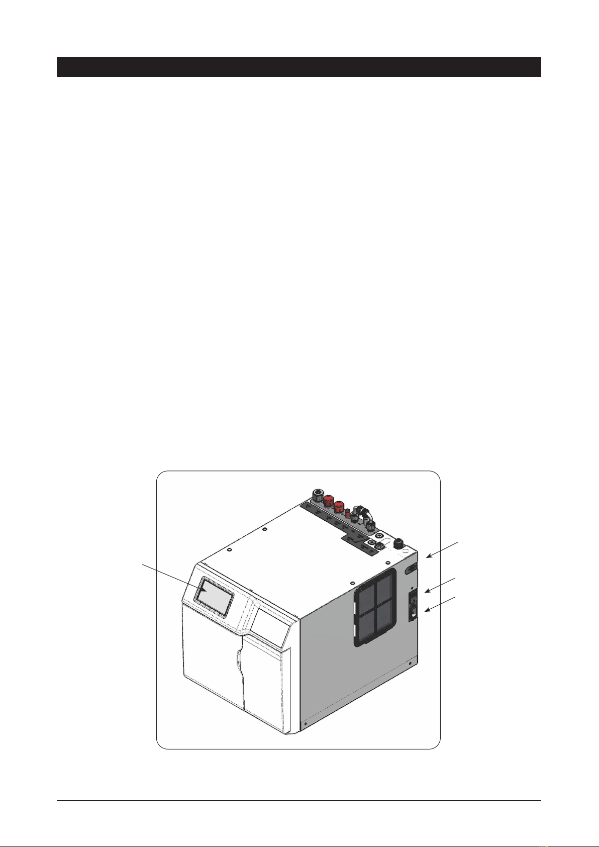
5. This unit must be installed with adequate clearances of 50mm on all sides,
and 200mm above, to allow for air circulation. Additional means of ventilation
is critical if the vent kit, as supplied, cannot be fitted.
6. Flush water supply lines before any plumbing connections are made, to
prevent sediment from affecting operation.
7. The Command Centre must not be located near, or cleaned with water jets.
8. This product is designed for indoor use and must not be installed outdoors or
exposed to the elements of nature.
9. For safe operation, the HydroTap is designed to be installed, commissioned
and used within 48 hours. Should the HydroTap not be required for an
extended period of time (72 hours or more), do not fill and commission the
HydroTap until ready for first use.
10. For water taste and quality reasons, following any non-use period of more
than 72 hours, Zip recommends to perform a system flush. Failure to flush
the system may affect water quality.
11. Due to the process of continuous improvement, Zip Water reserves the right
to change details mentioned in this manual, without notice.
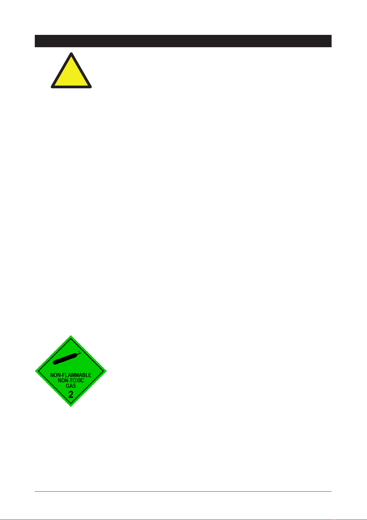
2.64 kg CO2Cylinder Warnings:
•
Pressurised container.
•
Protect from sunlight.
•
Contains gas under pressure, may explode if heated.
•
Do not expose to temperatures exceeding 50˚C.
•
Do not pierce or burn, even after use.
•
Do not expose to naked flame or any incandescent material.
•
Keep out of reach of children.
•
High concentration of gas may cause asphyxiation.
•
Use only in ventilated areas.
•
Store in a location with a volume of no less than 50 cubic meters for each
2.64 kg bottle.
•
Use only in an upright position.
•
This bottle must be used with the approved pressure regulator.
•
Avoid shock.
•
Use according to MSDS (Material Safety Data Sheet).

Page 8 of 32 802265 v3.05 09.20 HT BCS Compact Commercial Instructions
Parts supplied Description
1 x HydroTap
Tap with hoses
(Classic tap shown)
1 x HydroTap
Command Centre
with air and water
filters
1 x Mains water
connection hose
1 x Connector +
Strainer Sub-assy
Vent Kit
1 x Inlet vent
1 x Outlet vent
9 x Screws
1 x CO2gas cylinder
& regulator assy.
HydroTap Booster
Water System with
connection hoses.
(Model BCSHAV
140/75)
1 x Flow Restrictor
and Tee piece for
BCSHAV and
selected models
1 x Installation
Instructions
(this book) and
1 x User Guide
Major Components and Accessories
Accessories Description
Softener
and head assembly
Font Kit for
Arc & Cube Models
Font Kit for Classic &
Elite Models
Replacement Filter
Disabled Lever Kit
5-in-1 Upgrade Kit
(Arc mixer shown)
Install
Instruct
User
Guide

802265 v3.05 09.20 HT BCS Compact Commercial Instructions Page 9 of 32
Technical Specifications
Model
Cups of
Boiling
Water per
Hour
Glasses
of Chilled
Water per
Hour
BCS 100 75
Products covered by these instructions:
** Add an extra 4-5 kg when full of water
Capacity
Boiling
(cups)
Capacity
Chilled
(glasses)
Power
Outlets
required
Power
Rating
(kW)
Boost
Rating
(kW)
Unit Dimensions
W x D x H (mm)
**Dry
Weight
(kg)
Boiling Chilled Sparkling
BCS100/75 100 75 1x10A 2.15 N/A 339 x 460 x 335 30
All-In-One
BCSHA-A 100/75 100 75 1x10A 2.15 N/A 339 x 460 x 335 30
BCSHA-AV 140/75 140 75 1x10A 2.15 2.2 339 x 460 x 335 30
5-In-1
BCSHA 100/75 100 75 1x10A 2.15 N/A 339 x 460 x 335 30
Models
BCS Boiling ; Chilled and Sparkling
BCSHA 5 in One
BCSHA-A All-In-One Mains option
BCSHA-AV All-In-One Vented option
D Disabled lever controls (optional accessory)
Note:
• The Cup measurement =167ml and the Glass measurement = 200ml
•
Chilled water will continue to be dispensed after the rated capacity has been used, although this may
be at slightly higher temperature.
Before Installation
Before installing ensure that the following have been provided at the
installation site:
•
Review all the technical specifications.
•
Ensure the underbench can support the product weight when full of water
(allow an extra 4-5kg when full)
•
Sufficient space in the cupboard to install all of the Command Centres in accordance with these
Installation Instructions. Refer to technical specification for dimensions. Make allowance for a booster
heater and / or water softener if required. Refer to section 3 & 4, for Installation instructions.
•
For Zip HydroTap 100/175 models, a 220-240V, 10A AC power outlet will be required. For Zip
HydroTap 140/75 models, two 220-240V, 10A power outlets will be required (one outlet for the Zip
HydroTap and the other for the Booster heater).
!

Page 10 of 32 802265 v3.05 09.20 HT BCS Compact Commercial Instructions
NoteNote: Check all cable and hose lengths against inlet /outlet positions before proceeding
(See section 5 for general layout)
•
A potable water supply connection with isolating valve inside the cupboard within reach of the braided
hoses and positioned so that the connection point and the stop cock will not be obstructed when the
Command Centres are installed.
•
For the mains pressure All-IN-ONE, an external hot and cold water supply will be required.
•
If an external filtration or water softening device is required, then it is important to allow extra space for
these items.
•
A cold water supply with a minimum working pressure of 300kPa and a maximum working pressure of
700kPa connected via an isolation valve.
•
The fitting of an air flow duct, attached to the right hand side of the unit, requires a rectangular cut size
of 284mm x 45mm, to provide adequate warm air displacement. See section 2.
•
The appliance must be placed with it’s base in a horizontal position.
IMPORTANT!
Do not proceed with the Installation if these requirements are not met.
Before Installation
Special Tools Required:
In addition to normal tools, the following will be required:
For the standard and Mixer taps:
•
35mm diameter sheet metal hole punch for sink tops (not supplied)
•
35mm diameter hole saw for timber bench tops (not supplied)
•
Nut runner tube spanner (supplied) for fixing tap assembly.
For the All-In-One tap:
•
50mm diameter sheet metal hole punch for sink tops (not supplied)
•
50mm diameter hole saw for timber bench tops (not supplied)
•
Nut runner tube spanner (supplied) for fixing tap assembly.
Section 1
Tap Installation
Refer to the Tap installation instructions, supplied with the Tap.

802265 v3.05 09.20 HT BCS Compact Commercial Instructions Page 11 of 32
2.1 Ventilation for All Models
Proper air circulation must be provided for all Boiling and Chilled models. The system will operate correctly
only if the recommended air gaps are achieved during Installation. The minimum requirement is for a 50mm air
gap either side and 300mm above of the Command Centre.
It is important that the 4mm door buffers (For all installations ) are fitted to the inside edge of the cupboard
door to allow sufficient air circulation inside the cupboard. (See the diagram below).
IMPORTANT: Allow clearance of 50mm either side, and 200mm above the Command Centre.
!
When installing air flow ducts, the following tools will be required:
•
Jigsaw and 12mm Drill
•
Keyhole or Wall Board saw.
Section 2
Ventilation
Min 200mm
460mm
4 min.
Buffer Pad
Clear Gap

Page 12 of 32 802265 v3.05 09.20 HT BCS Compact Commercial Instructions
Cool air IN
Warm air
OUT
Ventilation
Air inlet vent position
Airflow through the cupboard
B
D
Door outlet vent
1. Drill four pilot holes
12mm dia.
2. Finish the cutout using
a jig saw and keyhole
or Wall Board saw
If the air flow, using the silicon door buffers, is insufficient, it will be necessary to fit a standard HydroTap vent
kit, which ensures heat dissipation through natural convection via installed vents.
For high use applications, where the cupboard space temperature is near 35°C, or higher, the inlet vent
(See Item B below) and silicon buffers, need to be fitted. If the airflow is still insufficient to maintain normal
operating temperatures then the inlet vent and door outlet vent (See item D below) will need to be fitted.
Alternatively a fan kit may be installed, using the AUX din plug of the right hand side of the appliance
(Contact your local service centre for availability).
Note: The vent kit has to be installed in a way that allows air to be drawn in from the bottom of the cupboard
and expelled through the top of the cupboard. Therefore placement of the outlet vent should be towards the
top of the door or on the side of the cupboard.
2.2 The following instructions are critical if there is insufficient cupboard air
circulation
Cut-out details

802265 v3.05 09.20 HT BCS Compact Commercial Instructions Page 13 of 32
Typical Cut out procedure for
B
Ventilation
Cut-out details
Air inlet vent
1. Mark out and cut the air inlet and door outlet holes as shown
2. Ensure the air inlet vent and air outlet vent are positioned at opposite ends
of the same cupboard space.
3. Fit the inlet vent, as shown and secure with 5 screws
4. Fit the outlet vent, as shown in the hottest part (top) of the cupboard and
secure with 4 screws
BD

Page 14 of 32 802265 v3.05 09.20 HT BCS Compact Commercial Instructions
Section 3
Booster Heater
3.1 Product Description
The boost unit is a compact, electronically
controlled auxiliary water heater. It is intended
to provide pre heating of water before it enters
the Zip HydroTap G4 boiling tank. The Booster
is supplied with the BCSHAV model. However,
it may be later installed, as an accessory for the
BCS model, to increase its delivery.
339 mm
Booster Specifications:
Rating Unit
Nominal Power Rating 2.2 kW
Nominal Current 10 A
Electric Supply 50Hz AC 230 V
Elect ex and plug (black) - 1 metre length (with 90º Australian plug) 10 A
Fixed Flow Rate 1.2 L/min
Minimum water pressure 200 kPa
NoteNote 1: water connection
Blue marking: water in
Red marking: water out.
The braided hoses cannot be length-
ened.
NoteNote 2: The electrical cable length
is 1.0 metre.
NoteNote 3: Position the Booster within
reach of the fixed hose lengths, keep-
ing the Booster as close as possible
to the Command Centre inlet/outlet
fittings.
NoteNote 4: Ensure the Booster heater
is mounted in an upright position (as
shown) with a horizontal base.
Mount base
horizontally

802265 v3.05 09.20 HT BCS Compact Commercial Instructions Page 15 of 32
Booster Installation
Tilt Forward Lift UP
Release
NOTE: Remove the backing plate for wall mounting
Take care
not to break
the lower
clips when
removing or
installing the
Booster
!
Installation
3.2 Installation Procedure
Site requirements
•
The appliance must only be installed in a frost-free area. Never expose appliance to frost.
•
The appliance is designed for wall mounted installation and must be installed with water connectors
facing upwards.
•
The appliance complies with protection class IP 25.
•
The 400mm braided hoses supplied with the unit cannot be lengthened.
•
The 90°elbow hose ends should be fitted to the inlet and outlet connections on top of the Booster.
•
The hot water outlet hose must be thermally insulated with the insulation provided.
3.3 To Remove / Install the appliance
1. Insert a flat head screwdriver all the way into the lock.
2. Gently angle the screwdriver upwards by approximately 10° as shown in the image below.
3. Pull the appliance forwards by approximately 15° as shown.
4. Carefully pull the appliance upwards to complete the removal process. Take care not to break the
lower clips
5. To install, place the appliance on the wall bracket and snap into position (see illustration below).

Page 16 of 32 802265 v3.05 09.20 HT BCS Compact Commercial Instructions
NOTE 1: This appliance is intended for use with the Zip HydroTap Command Centre.
NOTE 2: Water connections must be pointing vertically upwards.
NOTE 3: The booster unit should be installed as close as possible to the Zip
HydroTap Unit as the 400mm connection hoses cannot be lengthened.
Booster Installation
3.4 Braided hose connection
s
1. The cold water inlet (blue) and hot water outlet (red) are marked on the rating plate. Connect the
braided hoses from the ‘Bypass Out’ fitting to the water inlet of the booster unit (marked blue) and
from the outlet of the booster unit (marked red) to the ‘Bypass IN’ fitting on the Zip HydroTap unit.
Avoid exerting any mechanical pressure on the appliance. This can be achieved by applying a spanner
on the flats of the inlet and outlet connections when tightening the braided hose connectors. Do not
overtighten! Tighten the braided hoses by hand, then turn an additional 90°- 180° with a spanner
2. Once the water connections have been made, check for any leaks and rectify as necessary.
Hot Water
Connection
(outlet, G1/2”)
Strainer
Cold Water
Connection
(inlet, G1/2”)
Hold the hexagon while
tightening the braided
hose fittings
Braided Hoses
Typical Installation

802265 v3.05 09.20 HT BCS Compact Commercial Instructions Page 17 of 32
STORAGE WARNING:
A CO2gas cylinder of 2.640kg must be installed in an open plan area or in an enclosed room, with a volume
no less than 50m3. If more than 1 gas cylinder containing CO2is present within the same location, the
recommended ventilated area should be in proportion to the number of gas cylinders stored in that location.
A ventilated area is a non-enclosed area which could include the kitchen, living room etc.
See gas bottle and MSDS sheet for a complete list of warnings (see: www.zipwater.com).
4.1 Secure the cylinder cradle
After marking out the cradle location, secure it to a suitable wall, within 1 metre of the unit. Make sure the gas
bottle, regulator and cradle assembly can comfortably fit, with sufficient clearances, before securing the cradle
inside the cupboard. Due to regulatory requirements the gas bottle must be stored securely and in an upright
position. Secure the bottle with the hook-and-loop straps provided.
4.2 Connect the regulator:
After removing all packing material, fit the regulator to the gas bottle as shown in the diagrams. Ensure the
plastic seal is fitted securely inside the large chrome nut, before attaching to the gas bottle. If the plastic seal
is not an easy fit over the spigot, soak it in hot water, before re-applying. Do not force the seal to fit.
Turn the regulator OFF by rotating the regulator knob, all the way out, in an anti-clockwise direction.
NOTE: Two plastic seals are supplied with a new regulator. Only one is required, the other is supplied as
a spare part.
4.3 Connect the gas hose:
Connect the braided gas hose to the top of the Command Centre via the John Guest fitting marked ‘Gas IN’
Then connect the threaded end to the regulator (Do not lose the small sealing olive). When commissioning,
first, turn the regulator, grey knob, all the way out (anticlockwise). Then turn the gas ON by rotating the black
knob on top of the cylinder, anti-clockwise. Finally, adjust the outlet pressure by rotating the grey regulator
knob in a clockwise direction, to between 2.7- 3.0 bar (green zone)
NOTE:
The arrow should sit in the green zone of the regulator gauge; it should not fall in the red or yellow
sections.
4.4 Test for gas leaks:
When commissioning, use soapy water to perform a leak test. Apply the soapy water to the gas connections
using a sponge or brush. If any bubbles appear and grow, there is a gas leak at the connection. Clean away
the soapy residue and tighten or refit the leaking connection. Make sure the gas is turned off when tightening
or refitting the leaking connection.
Fit the gas bottle into the cradle and secure with the Hook-and-loop strap. Ensure the bottle is in an upright
position.
NOTE:
Care must be taken when working with high pressure carbon dioxide, and in no cases should the
normal operating pressure of between 2.7- 3.0 bar be exceeded.
!
Section 4
2.64kg CO2Cylinder

Page 18 of 32 802265 v3.05 09.20 HT BCS Compact Commercial Instructions
After replacing a bottle or after making a gas connection, perform a Leak Test:
Stage1:
1. Turn the gas OFF
2. Using soapy water applied with a sponge, or with a brush, cover all of the gas joints with a liberal
amount of suds.
Stage 2:
1. Turn ON the gas
2. Adjust the pressure to between 2.7- 3.0 bar
3. Inspect the joint for leaks
4. If any bubbles appear, the joint will need to
be resealed.
CO2Regulator
This gauge shows the pressure in the bottle
and indicates when the bottle is empty. Initial
bottle pressure will be 35-40 bar.
This gauge shows the adjustable limit (2.7- 3.0 bar)
required for the HydroTap to function correctly
Pressure regulating knob
ON - OFF knob
Green zone
Relief
valve
NOTE:
Take care not to lose
the small sealing olive
in the end of the braided
hose. This olive is
necessary to ensure a
gas tight seal between
the braided hose and the
regulator.

802265 v3.05 09.20 HT BCS Compact Commercial Instructions Page 19 of 32
B
Rotate 90°
only
1
2
3
4
If no external lter
is installed, select
position A.
If an external filter
is installed, select
position B
NOTE:
Before you install a unit, determine whether a water softener or an external filter is required.
5.1
External Bypass Valve
The diverter bypass valve allows the user to choose to have the boiling feed water bypass the internal filter
and only be filtered by the external filtration. This diverter valve is located at the rear panel of the Zip HydroTap
Command Centre on the filter door side. See the diagram below to determine which filter bypass position you
need for your product.
Section 5
Command Centre Installation
A
Rotate 90°
only
1
2
3
4
5.2 Hose and tube fitting
•
Remove all caps from the top of the Command
Centre (except the mixer caps)
•
Only remove the mixer caps if a mixer tap is to be
fitted.
•
Fit the foam insulation to the Blue and to the
White tubes after trimming them to length
•
Install the mains water braided hoses to the
Command Centre before locating the unit in
place.
NOTE: Do not overtighten
Connector + Strainer
90° Bend end
of Braided Hose
To HydroTap
Command Centre
Braided hose for
Mains Water Supply
From Mains
Water Supply

Page 20 of 32 802265 v3.05 09.20 HT BCS Compact Commercial Instructions
Installation Instructions
5.4 Install carbonation valve
5.3 John Guest fittings (Insertion and removal)
Be careful when cutting the poly tube so that there are
no rough edges and that the tube is not distorted.
1. Use a sharp knife to ensure the tube has a clean,
straight edge. Do not cut at an angle.
2. Remove any swarf or unwanted material.
3. Push the tube into the John Guest fitting making
sure all connections to the John Guest fittings are
pushed in past the “O”ring to full depth, at least
15-16 mm.
4. Check for a good joint by pulling back on the tube.
If the tube comes out of the fitting, repeat the
above step.
5. To remove the tube, press the collet into the fitting
and at the same time pull back on the tube.
1. Fit the carbonation valve to the white tube, as close
as possible to the Y-connector from the tap.
2. Use the white tube to connect the carbonation valve
to the sparkling outlet connection on top of the Com-
mand Centre.
3. The carbonation valve has an adjustable ow rate.
The optimum setting for the valve is between 1.2 -
1.6 litres per minute. Using a 6mm Allen key or a
large at blade screw driver, you can adjust the ow
on the valve. See Section 7.7 for carbonation valve
ow rate adjustment.
Warning - Take care NOT to use excessive
force during adjustment of the valve.
!
Sparkling Water Flow
This manual suits for next models
3
Table of contents
Popular Water System manuals by other brands

Presto
Presto Q4357 installation instructions

ABANTERA
ABANTERA Neo GreenWashing user manual

Clear Comfort
Clear Comfort CCW300A Installation, operation & maintenance manual

Pentair
Pentair Raychem HWAT System Installation and operation manual

Halsey Taylor
Halsey Taylor HTVZDBL*1C series owner's manual

Intex
Intex ECO 7220 owner's manual

Sterilight
Sterilight Viqua S2Q-OZ owner's manual

Intewa
Intewa Rainmaster Favorit-SC 40 Installation and user manual

Elkay
Elkay LZWSRK -EZH2O Care & use manual

ClayTech
ClayTech CMS B3A1 owner's manual

Daikin
Daikin Solaris EKSH26P quick start guide

Watts
Watts PWR2511 Series Installation, operation and maintenance manual