Ziton A70E-2 Assembly instructions

© 2016 UTC Fire & Security. All rights reserved. 1 / 4 P/N 10-5211-501-AZ70-12 • ISS 29JUN16
A70E-2 Conventional Zone Interface Module
Installation Sheet
Description
The A70E-2 Conventional Zone Interface Module provides the
interface between a conventional zone of detectors and an
addressable loop. The zone of conventional detectors appears
as a single addressable device on the addressable loop.
The module includes the following features:
• Red LED to indicate alarm condition
• Yellow LED to indicate fault condition
• DIN rail or surface mounting
• 24 V or loop powered
• Built-in head-out operation
• Drives intrinsically safe equipment
Installation
The A70E-2 contains no user-serviceable parts and should not
be disassembled.
To install the device:
1. Verify that all field wiring is free of open circuits, short
circuits, and ground faults.
2. Make wiring connections as shown in Figure 2 and
Figure 3.
A P15 or 35 mm DIN rail can be used. See Figure 1 for
mounting hole dimensions and locations. The mounting
hole diameters are 4 mm and centres are at 40.5 and
67.0 mm.
Figure 1: A70E-2 dimensions
Wiring
Connect the supplied transient suppression devices
(transzorbs) as shown in Figure 2.
Figure 2: Transzorb wiring

2 / 4 P/N 10-5211-501-AZ70-12 • ISS 29JUN16
Operational settings
Figure 3: A70E-2 Conventional Zone Interface wiring
Setting the address
The A70E-2 Conventional Zone Interface contains a 7-way DIP
switch, which is used to set the device address in binary code.
The switch may be set to represent all addresses from 1 to
127. See Figure 3 for the location of the address DIP switch.
The address is the sum of the switch values, as shown in the
following table. Note that the switch values determine the
address, not the switch numbers.
Switch
n
umber 1 2 3 4 5 6 7
Code value
1 2 4 8 16 32 64
Power supply selection – J1
Jumper J1 is used to select between an externally powered or
loop powered conventional zone. For the location of J1, see
Figure 3.
Note: Remove both jumpers before inserting either of them.
External 24 VDC power
Note: The device will go into fault if the jumpers are left out or
if external power is removed when J1 is in the External 24 VDC
Power position.
Loop power
Operating mode selection
A 2-way mode DIP switch is used to select the conventional
zone operating mode. See Figure 3 for the location of the
mode DIP switch.
Table 1: Operating mode selection
Switch selection
Mode
SW 1 and 2 OFF
Normal mode, see Figure 4
SW 1 ON
and 2 OFF Intrinsically safe mode, see Figure 7
SW 1
and 2 ON Intrinsically safe mode, see Figure 7
SW 1 OFF and 2 ON
Head-out mode, see Figure 5 and Figure 6
Note: It is not possible to be in both intrinsically safe and head-out
mode.
Table 2: LED indicator
LED indicator
Status Description
Red alarm LED
[1] Flashing Conventional zone fire
and/or switched output
operated
Yellow fault LED
[1] Flashing Conventional zone fault
Yellow fault LED
Double flashing Power fault
[1] Once registered by the panel, the alarm LED output is maintained
by the panel until reset.
[2] The fault LED is nonlatching.
Application notes
Figure 4: Normal mode operation
Figure 5: Head-out detection mode for Z6x0-3 detectors

P/N 10-5211-501-AZ70-12 • ISS 29JUN16 3 of 4
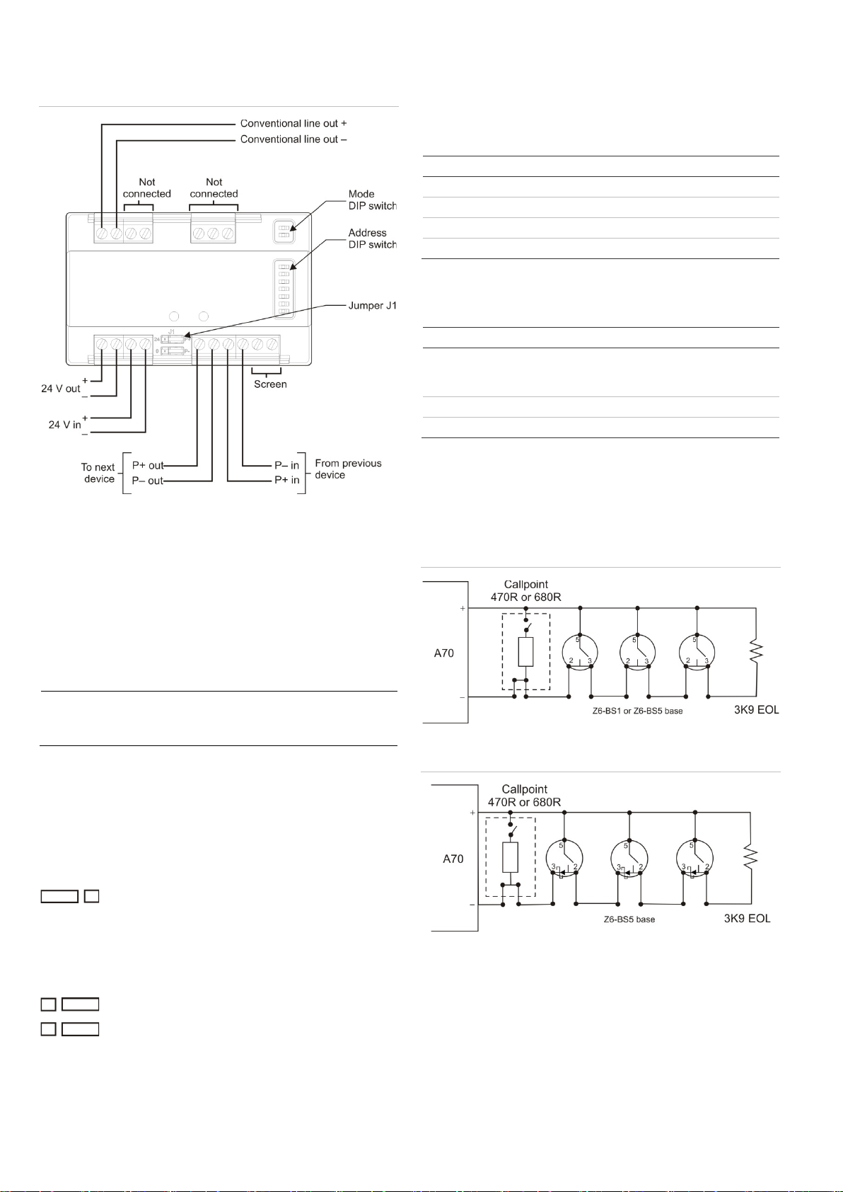
Figure 6: Head-out detection mode for detectors without an
in series diode, e.g. Z620-1 &-2 (consult manufacturer)
Figure 7: Intrinsically safe mode (using intrinsically safe
detectors)
Specifications
Application
Indoor use
Power supply requirements
External power supply
Loop power
Max. line drop
19 to 30 VDC
20 Volt pulsed addressable loop
2 V
Current consumption
See Table 1
Mechanical
Material
Colour
Dimensions (L x W x H)
Weight
Mounting method
Moulded ABS
White
85 x 78 x 27 mm
80 g
Surface or DIN rail
Monitoring (conventional zone)
Open and short circuit fault with a
3.9 kΩ EOL resistor (normal
conventional devices) or 8.2 kΩ
EOL resistor (intrinsically safe
devices)
Head-out operation with 3K9
resistor available with Z6x0-3
detectors or other detectors with
series supply diode. Requires
base with Schottky diode (for
example, Z6-BS5. Add a series
diode to the base – see Figure 6
to use other detectors).
Compatibility
Addressable side
Conventional side (max. 15
devices)
ZP3 and ZP2 addressable
systems
Ziton 610, 620, 630
Hochiki intrinsically safe devices
(these must be used in
conjunction with a GBX2000
galvanic isolator)
Callpoint
resistor required 470R or 680R
Wiring
Belden 9501 or equivalent
screened cable
Operating environment
Temperature
Relative humidity
−10 to +80°C
20 to 95% noncondensing
Storage temperature
−10 to +80°C
Detector compatibility
Operating voltage (normal,
head-out mode)
Operating voltage (intrinsically
safe mode)
Alarm clamp voltage
Current consumption (all
detectors, excluding EOL
resistor)
Reset supplied by A70
12.5 to 20 VDC
14 to 20 VDC
3 to 9 V
1.5 mA (normal, head-out mode)
3 mA (intrinsically safe mode)
2.4 s power disconnect
Table 1: Current consumption
From external supply From loop
Source
Quiescent Worst case
(S/C fault) Quiescent Worst case
(S/C fault)
Externally
powered
7.3 mA 36.6 mA 0.8 mA 10 mA
Loop
powered
8.3 mA 24.6 mA
Regulatory information
This section includes both regulatory information and a
summary on the declared performance according to the
Construction Products Regulation 305/2011. For detailed
information, see the product Declaration of Performance.
Certification
Certification body
0370
Declaration of
Performance number
360-5211-0399
Year of first CE
marking
10
Product Identification
A70E-2
Intended use
See the product Declaration of Performance
Essential
characteristics
See the product Declaration of Performance
Manufacturer
United Technologies Safety System Co., Ltd.
80, Changjiang East Road, QETDZ, 066004
Qinhuangdao HEBEI, China
Authorized EU manufacturing representative:
UTC Fire & Security B.V.
Kelvinstraat 7, 6003 DH Weert, Netherlands
2012/19/EU (WEEE directive): Products
marked with this symbol cannot be disposed
of as unsorted municipal waste in the
European Union. For proper recycling, return
this product to your local supplier upon the
purchase of equivalent new equipment, or
dispose of it at designated collection points.
For more information see:
www.recyclethis.info.
Contact information
For contact information, see www.utcfssecurityproducts.eu.

4 / 4 P/N 10-5211-501-AZ70-12 • ISS 29JUN16
Popular Recording Equipment manuals by other brands

SILENTRON
SILENTRON Nice Sil Bus Instructions and warnings for installation and use

Aiwa
Aiwa HV-FX7800 - SERVICE Service manual

Cochlear
Cochlear Nucleus 8 user guide

Pro-Ject Audio Systems
Pro-Ject Audio Systems Box S USB Instructions for use

ENCORP
ENCORP iSAVER DPFC 450 operating manual

HP
HP 98641A Product support