ZLG CANDTU-200UWGR User manual

Product User Manual
CANDTU-200UWGR
CAN Bus Message Records and Wireless Data Transmission Equipment
User Manual
UM01010101 V1.03 Date: 2019/03/15
Category
Contents
Keywords
CAN-Bus message recording and storage
Description
Product User Guide
©2021 Guangzhou ZLG Microelectronics Technology Corp.,Ltd.

CANDTU-200UWGR
CAN Bus Message Recording and Wireless Data Transmission Equipment User Manual
©2021 Guangzhou ZLG Microelectronics Technology Corp.,Ltd.
1
User Manual
Revision History
Version
Date
Description
V0.90
September 18,
2017
Created
V1.01
October 10, 2017
Added the network data frame format
V1.02
February 8, 2018
Modified the firmware upgrade operation, and added the
description of the online upgrade function
V1.03
March 15, 2019.
Updated the document header and footer and "Sales and
Service Network" content, and added the "Disclaimer" content

CANDTU-200UWGR
CAN Bus Message Recording and Wireless Data Transmission Equipment User Manual
©2021 Guangzhou ZLG Microelectronics Technology Corp.,Ltd.
2
User Manual
Contents
1. Product Introduction.....................................................................................1
1.1 Product Overview...........................................................................................1
1.2 Features.........................................................................................................3
1.3 Typical Applications........................................................................................3
2. Product Specifications .................................................................................5
2.1 Electrical Parameters.....................................................................................5
2.2 Operating Temperature..................................................................................5
2.3 Protection Level.............................................................................................5
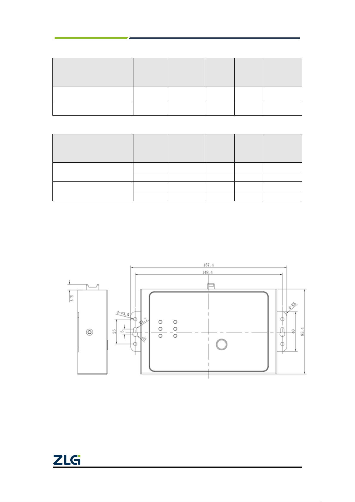
2.4 Mechanical Dimensions.................................................................................6
3. Hardware Interfaces.....................................................................................7
3.1 Interface Layout.............................................................................................7
3.2 Indicators........................................................................................................7
3.3 DB9 Interface, Flange Terminal Interface......................................................8
3.3.1 Power INTERFACE ................................................................................8
3.3.2 Switch Output Interface..........................................................................8
3.3.3 Switching Value Input Interface............................................................10
3.3.4 CAN-bus Interface................................................................................11
3.3.5 LIN-Bus Interface..................................................................................12
3.4 USB Interface...............................................................................................13
3.5 SD Card Interface........................................................................................13
3.6 SIM Card Interface.......................................................................................13
4. Configuration Tool Installation and Introduction .........................................15
4.1 Software Installation.....................................................................................15
4.2 Functions......................................................................................................17
4.2.1 Device Selection...................................................................................18
4.2.2 Device Name Configuration..................................................................19
4.2.3 CAN Configuration................................................................................19
4.2.4 LIN Configuration..................................................................................21
4.2.5 DO Configuration..................................................................................22
4.2.6 Filtering.................................................................................................23
4.2.7 Triggering..............................................................................................24
4.2.8 Data Converter .....................................................................................28
4.2.9 GPS Track.............................................................................................30
4.2.10 Storage Space Allocation .....................................................................32
4.2.11 GPS configuration.................................................................................33
4.2.12 SMS Configuration................................................................................34
4.2.13 Network Configurations........................................................................34
4.2.14 Network Transmission Filtering............................................................35
4.2.15 Continuous Transmission After Disconnection.....................................36
4.2.16 Network Transmission Encryption (To Be Customized).......................36
4.2.17 Network Frame Format.........................................................................37

CANDTU-200UWGR
CAN Bus Message Recording and Wireless Data Transmission Equipment User Manual
©2021 Guangzhou ZLG Microelectronics Technology Corp.,Ltd.
3
User Manual
4.2.18 Network Server Settings.......................................................................38
4.2.19 Menu Operation....................................................................................41
4.2.20 Setting and Getting the Device Clock...................................................42
4.2.21 Downloading and Obtaining Device Configurations.............................43
4.2.22 Pausing and Resuming records...........................................................43
4.2.23 Clearing Device Storage.......................................................................43
4.2.24 Device INFORMATION.........................................................................44
5. USBCAN Function.....................................................................................45
5.1 CANTest Test Software Installation..............................................................45
5.2 Quick Use of the USBCAN Function...........................................................47
6. Quick Instructions ......................................................................................50
6.1 Operational Guidelines ................................................................................50
6.1.1 Configuration ........................................................................................50
6.1.2 Records.................................................................................................50
6.1.3 Upgrade................................................................................................50
6.1.4 Changing the Card................................................................................53
Product fault report form ................................................................................54
Product return procedure...............................................................................55
Disclaimer......................................................................................................56

CANDTU-200UWGR
CAN Bus Message Recording and Wireless Data Transmission Equipment User Manual
©2021 Guangzhou ZLG Microelectronics Technology Corp.,Ltd.
1
User Manual
1. Product Introduction
1.1 Product Overview
In the CAN bus troubleshooting, the biggest difficulty is occasional faults. This makes
engineers or even CAN experts unable to accurately identify the fault cause. For example,
the pitch system of the wind turbine had a CAN data transmission interruption in 72 hours;
the dashboard of a new energy vehicle appeared "blank" once during a 10,000 km drive,
but this could not reoccur; the high-speed train experienced an emergency deceleration
due to abnormal CAN communication during a 2,000 km journey. These occasional
CANFD communication exceptions have frightened engineers like time bombs. If one
CAN bus data recorder is installed on an occasion prone to faults, it is equivalent to a
"black box" to record CAN data, which helps analyze the fault cause.
Guangzhou ZLG Electronics Co., Ltd., as a leading manufacturer of the domestic
CAN bus, has developed CANDTU series products for troubleshooting CAN buses, which
can record CAN messages offline and perform GPRS and 4G transmission. It can easily
complete the message recording and on-site monitoring of applications such as vehicles,
ships, elevators, wind turbines, and construction machinery.
CANDTU-200UWGR series products are storage-type 2-channel CAN bus data
recorders. The products can run independently from the PC and store CAN message data
for a long time, which facilitates analysis and troubleshooting. The recorder can transfer
the recorded data to a PC via an SD memory card. After format conversion of the raw data,
users can analyze and evaluate the recorded data offline by using CANoe and
CANScope.
CANDTU-200UWGR also supports 4G communication, which can upload the
data on the CAN bus to the specified server. Support GPS/Beidou positioning and
record the device localization real time.
The CANDTU-200UWGR is also a CAN-Bus bus communication device that
complies with USB2.0 high-speed specification protocol and integrates two CAN
interfaces. The PC can be connected to the CAN-Bus network through the USB bus of the
device to realize the data mutual transmission between the PC and the CAN-Bus network.

CANDTU-200UWGR
CAN Bus Message Recording and Wireless Data Transmission Equipment User Manual
©2021 Guangzhou ZLG Microelectronics Technology Corp.,Ltd.
2
User Manual

CANDTU-200UWGR
CAN Bus Message Recording and Wireless Data Transmission Equipment User Manual
©2021 Guangzhou ZLG Microelectronics Technology Corp.,Ltd.
3
User Manual
1.2 Features
CAN channel
Number of channels: two user-configurable CAN channels
Interface type: high-speed CAN (optional fault-tolerant CAN,
single-wire CAN)
Baud rate: arbitrarily programmable between 5Kbps and 1Mbps
Maximum received data flow: greater than 7,000 frames/s
Surge protection: 2 kV (Class B)
Electromagnetic isolation: 3.5 kV
LIN channel
One independent LIN channel
PC interface
Hi-speed USB2.0
Wireless 4G
transmission
Support Unicom, Telecom, Mobile 4G
GPS/Beidou
Positioning
The GPS/Beidou function can be enabled using the configuration
software, and the positioning information can be sent to the host
computer wirelessly
Positioning accuracy: 2.5 m
Recording, storage
Storage capacity: SD memory card of a maximum of 32 GB
Storage mode: all storage, timing storage
Full mode: rolling record, full stop
Trigger mode: conditional trigger, external trigger
Find and location: Manual time stamping
Data export:ASC or CCP data for CANoe, CANScope analysis
Digital output
One digital output
Real-time clock
Built-in rechargeable lithium battery
Software
resources
Supports the general configuration function library, which helps
users develop application programs with VC, VB, Delphi and C++
Builder
Supports the configuration tool CANDTU
Power supply
voltage
DC 7.5~48V
Power
consumption
2.568W
Range of
temperature
Operating temperature: -40℃to +85℃(without an SD card)
Storage temperature: -40℃to +85℃(without an SD card)
External dimension
155.5mm×85.3mm×27mm
1.3 Typical Applications
High-speed train operation fault detection and troubleshooting
Subway train running fault detection and troubleshooting
Train control system operation fault detection and troubleshooting
Wind turbine CAN communication fault detection

CANDTU-200UWGR
CAN Bus Message Recording and Wireless Data Transmission Equipment User Manual
©2021 Guangzhou ZLG Microelectronics Technology Corp.,Ltd.
4
User Manual
Multi-channel CAN communication records and fault analysis for traditional vehicles
and new energy vehicles
Ship CANFD communication fault detection and troubleshooting
Coal mine CAN communication fault analysis
Elevator operation fault detection and troubleshooting
Construction machinery operation fault detection and troubleshooting
Operation detection and troubleshooting of aerospace vehicles and ancillary
equipment

CANDTU-200UWGR
CAN Bus Message Recording and Wireless Data Transmission Equipment User Manual
©2021 Guangzhou ZLG Microelectronics Technology Corp.,Ltd.
5
User Manual
2. Product Specifications
2.1 Electrical Parameters
Table 2.1 Electrical parameters
Parameter Name
Conditions
Rating
Unit
Minimum
Typical Value
Maximum
Operating voltage
DC
7.5
48
V
Power consumption
2.568
W
2.2 Operating Temperature
Table 2.2 Operating temperature
Parameter Name
Conditions
Rating
Unit
Minimum
Typical
Value
Maximum
Operating
temperature
SD card not included
-40
-
85
℃
Storage
Temperature
SD card not included
-40
-
85
℃
Note: The operating temperature of the device depends on the SD card. The specifications are as
follows:
SD card specifications: -25°C to +85°C (operating temperature), -40°C to +85°C (storage temperature).
2.3 Protection Level
Table 2.3 Protection level-electrostatic discharge immunity test (IEC61000-4-2)
Interface
Conditions
Test Level
Test
Voltage
(kV)
Test
Result
Remarks
Power supply
Level 4
8
Class A
Contact
discharge
CAN bus
Level 4
8
Class A
Contact
discharge
LIN bus terminal
Level 4
8
Class A
Contact
discharge
Digital switch input and output
Level 4
8
Class A
Contact
discharge
USB
Level 4
8
Class A
Contact
discharge

CANDTU-200UWGR
CAN Bus Message Recording and Wireless Data Transmission Equipment User Manual
©2021 Guangzhou ZLG Microelectronics Technology Corp.,Ltd.
6
User Manual
Table 2.4 Protection level-electrical fast transient pulse group immunity test (IEC61000-4-4)
Interface
Conditions
Test level
Test
voltage
(kV)
Test
Result
Remarks
Power supply
Level 3
2
Class A
Capacitive
coupling
CAN bus
Level 3
1
Class B
Capacitive
coupling
Table 2.5 Protection level-surge (impact) test (IEC61000-4-5)
Interface
Conditions
Test level
Test
voltage
(kV)
Test
Result
Remarks
Power supply
Level 3
1
Class A
Line-line
Level 3
2
Class A
Line-ground
CAN bus
Level 3
1
Class B
Line-line
Level 3
1
Class B
Line-ground
Note: For details, see the attachment Electromagnetic Compatibility Test Report.pdf.
2.4 Mechanical Dimensions
Figure 2.1 shows the mechanical dimensions (unit: mm).
Figure 2.1 Mechanical dimensions
Note: For more detailed mechanical dimension drawings, contact our sales or technical support
personnel.

CANDTU-200UWGR
CAN Bus Message Recording and Wireless Data Transmission Equipment User Manual
©2021 Guangzhou ZLG Microelectronics Technology Corp.,Ltd.
7
User Manual
3. Hardware Interfaces
This section introduces the hardware interfaces of CANDTU series devices.
3.1 Interface Layout
Figure 3.1 shows the device panel layout.
Figure 3.1 Panel layout
3.2 Indicators
错误!未找到引用源。 describes the indicator status.
Table 3.1 Indicator status
Indicator
STATUS
State description
Power
supply
Always red
The power supply is normal
CAN0/1
Green normally on
Channel enabled
Green flashing
Channel data receive and send
Flash in red
Channel data error
Turn off
Channel closed

CANDTU-200UWGR
CAN Bus Message Recording and Wireless Data Transmission Equipment User Manual
©2021 Guangzhou ZLG Microelectronics Technology Corp.,Ltd.
8
User Manual
SYS
Green flashing
The system is normal
Flash in red
System error
REC
Green normally on
The SD card is normal
Green flashing
The SD card has data written
Flash in red
The SD card has data written, and the
channel storage space is insufficient
Turn off
The SD card is not detected
4G
Flash quickly (100 ms
on/800 ms off)
Search the network
Slow flash (100 ms on/3000
ms off)
Registered Successfully
Fast flash (100 ms on/300
ms off)
Data transmission
Closed
No SIM card or registration failed
3.3 DB9 Interface, Flange Terminal Interface
3.3.1 Power INTERFACE
The rated voltage of the power input of the device is 7.5-48 V DC . Table 3.2, Table 3.3,
and Table 3.4 list the interface schematic diagram, signal definition, and interface
specifications.
Table 3.2 Power interface
Type
Schematic Diagram
Flange terminal
Table 3.3 Flange terminal signal definition
Function
interface
Signal
definition
Signal description
Power
supply
VIN
positive electrode of power
GND_IN
negative electrode of power
Table 3.4 Power interface specifications
Parameter Name
Conditions
Rating
Unit
Minimum
Typical value
Maximum
Working voltage
DC
7.5
48
V
Power
consumption
2.568
W
3.3.2 Switch Output Interface

CANDTU-200UWGR
CAN Bus Message Recording and Wireless Data Transmission Equipment User Manual
©2021 Guangzhou ZLG Microelectronics Technology Corp.,Ltd.
9
User Manual
The device provides one channel digital output. The physical form of the interface is a
flange terminal. Table 3.5, Table 3.6, and Table 3.7 list the interface diagrams, signal
definitions, and interface specifications.
Table 3.5 DO interface
Type
Schematic Diagram
Flange terminal
Table 3.6 Flange terminal signal definition
Function
interface
Signal
definition
Signal description
DO
DO_P
Positive pole of the digital
output channel
DO_N
Negative pole of the digital
output channel
Table 3.7 DO interface specifications
parameter
Conditions
Minimu
m
Typical
value
Maximu
m
Unit
Contact load
DC 3A, resistive
30
V
Contact load
AC 3A, resistive
250
V
Contact Resistance
DC 1A, 24V
0.1
Ω
Isolation voltage
Valid value
4000
V
设备
输出单元
DO_P
DO_N
用户电源
用电设备
Figure 3.2 DO network connection
The switch output interface is a relay output type, and the interior is a relay contact.
The output control circuit is not limited by voltage and polarity, and can be 24 V DC or 220
V AC. Since it is a dry contact output, users need an external power supply to supply
power to alarm devices (such as buzzers). Figure 3.2 shows the connection.

CANDTU-200UWGR
CAN Bus Message Recording and Wireless Data Transmission Equipment User Manual
©2021 Guangzhou ZLG Microelectronics Technology Corp.,Ltd.
10
User Manual
The switch output interface is used to output the alarm signal. Through the
configuration tool, configurable trigger events include record full, CAN bus error, and SD
card status abnormality. In addition, the relay can be configured to be normally open or
normally closed based on user needs.
3.3.3 Switching Value Input Interface
The device provides one channel digital input. The physical form of the interface is a
flange terminal. Table 3.9, Table 3.10, and Table 3.11 list the interface diagrams, signal
definitions.
Table 3.8 DI interface
Type
Schematic Diagram
Flange terminal
Table 3.9 Flange terminal signal definition
Function
interface
Signal
definition
Signal description
DI
DI_P
Positive pole of the digital input
channel
DI_N
Negative pole of the digital input
channel
Table 3.10 DI interface specifications
parameter
Conditions
Minimu
m
Typical
value
Maximu
m
Unit
Logic 0 signal
DC
0
3
V
Logic 1 signal
DC
5
24
V
Isolation voltage
Valid value
3750
V
设备
输入单元
DI_P
DI_N
用户电源
开关设备
Figure 3.3 DI network connection

CANDTU-200UWGR
CAN Bus Message Recording and Wireless Data Transmission Equipment User Manual
©2021 Guangzhou ZLG Microelectronics Technology Corp.,Ltd.
11
User Manual
By using the configuration tool, the switch input interface can be configured as timing
recording mode and analog key-pressing mode.
1) The timing recording mode is used to regularly collect the switching status of external
equipment, such as valve closing and opening, motor start and stop, and contact
connection and disconnection. Figure 3.3 shows the connection diagram.
2) Simulate button mode can be used to simulate on-board buttons, including message
marking, pause recording, resume recording, and user upgrades.
3.3.4 CAN-bus Interface
The device provides two isolated CAN-Bus interfaces. The physical form of the
interface is a DB9 terminal. Table 3.11, Table 3.12, and Table 3.13 list the interface
schematic diagram, signal definition, and interface specification.
Table 3.11 CAN Interface
Type
Schematic Diagram
Pin description
DB9, pin
2:CAN0_L
3:CAN0_GND
5:CAN0_SHIELD
6:CAN0_GND
7:CAN0_H
2:CAN1_L
3:CAN1_GND
5:CAN1_SHIELD
6:CAN1_GND
7:CAN1_H
Table 3.12 Flange terminal signal definition
Function
interface
Signal
definition
Signal description
CAN
CAN_L
CAN data transceiving
differential inverted signal
CAN_GND
CAN isolated ground
CAN_H
CAN data sending and
receiving differential positive
phase signal
CAN_SHIELD
CAN shield ground

CANDTU-200UWGR
CAN Bus Message Recording and Wireless Data Transmission Equipment User Manual
©2021 Guangzhou ZLG Microelectronics Technology Corp.,Ltd.
12
User Manual
Table 3.13 CAN-Bus Interface Specifications
parameter
Minimu
m
Typical
value
Maximu
m
Unit
Communication baud rate
5k
1M
bps
Number of nodes
110
pcs
Dominant level (logic 0)
CANH
2.75
3.5
4.5
V
CANL
0.5
1.5
2
Recessive level (logic 1)
CANH
2
2.5
3
CANL
2
2.5
3
Differential level
Dominant (logic 0)
1.2
2
3.1
Recessive (logic 1)
-0.5
0
0.05
Maximum withstand
voltage of the bus pin
-18
18
Instantaneous voltage of
the bus
-100
+100
Isolation voltage (DC)
3500
V
Figure 3. 4 High-speed CAN typical network connection
The CAN bus adopts balanced transmission. ISO11898-2 stipulates: In the
high-speed CAN, a 120 ohm terminal resistor needs to be connected to the network
terminal node to eliminate signal reflection on the bus and avoid signal distortion. Figure
3.4 shows the high-speed CAN network topology.
The device has a built-in 120 ohm terminal resistance, which can be configured to
turn on or off by using the configuration tool CANDTU. For operation details, see 4.2.1.
Note: The bus communication distance and communication rate are related to the field application and
can be designed according to the actual application and related standards. The CAN-Bus cable can use
ordinary twisted pair, shielded twisted pair or standard bus communication cable. In long-distance
communication, the terminal resistance value needs to be selected according to the communication
distance, cable impedance and number of nodes.
3.3.5 LIN-Bus Interface
The device provides one independent LIN-Bus interface. The physical form of the
interface is a flange terminal. Table 3.9, Table 3.10, and Table 3.11 list the interface
diagrams, signal definitions,
See Table 3.14, Table 3.15, and Table 3.16.

CANDTU-200UWGR
CAN Bus Message Recording and Wireless Data Transmission Equipment User Manual
©2021 Guangzhou ZLG Microelectronics Technology Corp.,Ltd.
13
User Manual
Table 3.14 LIN interface
Type
Schematic Diagram
OPEN terminal
Table 3.15 OPEN, 5557 signal definition
Function
interface
Signal
definition
Signal description
LIN
LIN
LIN bus signal
GND
Digital ground
Table 3.16 LIN-Bus interface specifications
parameter
Minimu
m
Typical
value
Maximu
m
Unit
LIN line
Communication baud rate
20k
bps
DC voltage
-36
36
V
Dominant output level (logic 0)
0.75
V
Receiver dominant level (logic 0)
2
V
Receiver stealth level (Logic 1)
3
V
3.4 USB Interface
The device provides one USB interface. The device communicates with the PC over
the USB cable. The interface conforms to the high-speed USB2.0 protocol specification
and can communicate with PCs compliant with USB1.1 and USB2.0 standards. The
physical form of the interface is a Type-B USB port.
3.5 SD Card Interface
The device provides one SD card interface, which can support SD memory cards of a
maximum of 32 GB for storing CAN bus message data. The interface adopts a self-locking
card slot, and the SD card can be locked after the card is inserted according to the
direction of the casing logo to prevent accidental falling off during use. When pulling out
the card, just push it inwards to eject the SD card.
Note: Do not forcibly pull out the card when the device is in use. Otherwise, data loss or memory card
damage may occur! If necessary, after pausing the recording by pressing the button (or configuration
tool), gently push in and eject the SD card.. For details about how to pause the recording, see 4.2.22.
3.6 SIM Card Interface
The device provides one SIM card interface, which supports 4G communication

CANDTU-200UWGR
CAN Bus Message Recording and Wireless Data Transmission Equipment User Manual
©2021 Guangzhou ZLG Microelectronics Technology Corp.,Ltd.
14
User Manual
services of China Unicom, China Telecom and China Mobile. Put the SIM card into the
SIM card tray and push it into the SIM card slot; when pulling it out, push the yellow dot
next to it to take out the SIM tray.

CANDTU-200UWGR
CAN Bus Message Recording and Wireless Data Transmission Equipment User Manual
©2021 Guangzhou ZLG Microelectronics Technology Corp.,Ltd.
15
User Manual
4. Configuration Tool Installation and Introduction
4.1 Software Installation
1) Double-click the software installation package to install the software. The dialog
box shown in Figure 4.1 appears.
Figure 4.1 Installation wizard
2) Click "Next". The Choose Install Location dialog box appears.

CANDTU-200UWGR
CAN Bus Message Recording and Wireless Data Transmission Equipment User Manual
©2021 Guangzhou ZLG Microelectronics Technology Corp.,Ltd.
16
User Manual
Figure 4.2 Selecting an installation path
3) Click "Next". The dialog box shown in Figure 4.3 appears.
Figure 4.3 Selecting the "Start Menu" folder
4) Click "Install". The Install Driver dialog box appears.
Table of contents