ZLG CANFDBridge Smart User manual

Product User Manual
CANFDBridge Smart
Bridge
CAN(FD)-BUS Communication Products
User Manual
UM01010101 V1.03 Date: 2021/06/03
Category
Contents
Keywords
CANFDBridge CANFD-bus bridge
Description
Introduction to CANFD Smart Bridge
©2021 Guangzhou ZLG Microelectronics Technology Corp.,Ltd.

CANFDNET-400U
High-performance Four-channel CANFD Bus-to-Ethernet Converter User Manual
©2021 Guangzhou ZLG Microelectronics Technology Corp.,Ltd.
i
User Manual
Revision History
Version
Date
Reason
V1.00
September
11, 2018
Created
V1.01
March 12,
2019
Updated the document header and footer and "Sales and Service Network"
content, and added the "Disclaimer" content
V1.02
September
14, 2018
Added the product installation dimension drawing
V1.03
June 3, 2021
CAN(FD) baud rate range description

CANFDNET-400U
High-performance Four-channel CANFD Bus-to-Ethernet Converter User Manual
©2021 Guangzhou ZLG Microelectronics Technology Corp.,Ltd.
1
User Manual
Contents
1. Functions .....................................................................................................1
1.1 Overview.................................................................................................................1
1.2 Features..................................................................................................................1
1.3 Typical Applications................................................................................................2
2. Hardware .....................................................................................................3
2.1 Appearance and Installation Dimensions...............................................................3
2.2 Power Supply and USB Interface...........................................................................4
2.3 CAN(FD) Communication Interface .......................................................................4
2.4 Indicators................................................................................................................5
2.5 CAN Bus Connection .............................................................................................6
3. Driver and Configuration Tool Installation.....................................................8
3.1 Installing the Driver on Windows............................................................................8
3.2 Installing the Software CANCfg on the PC ..........................................................11
3.2.1 Configuration Tool Installation Example.....................................................11
4. Quick Instructions ......................................................................................13
4.1 Obtaining Basic Device Information.....................................................................13
4.2 Managing Device Configurations.........................................................................14
4.3 Configuring Parameters .......................................................................................15
4.3.1 CAN............................................................................................................15
4.3.2 Failback Example.......................................................................................18
4.3.3 Basic Forwarding Example........................................................................20
4.3.4 Filtering.......................................................................................................21
4.3.5 Frame Mapping..........................................................................................22
4.3.6 Frame Mapping Example...........................................................................24
4.3.7 Merging ......................................................................................................25
4.3.8 Merge Example..........................................................................................27
4.3.9 Split.............................................................................................................28
4.3.10 Split Example...........................................................................................29
4.4 Device Status Acquisition and Reporting.............................................................32
4.4.1 Obtaining the Device CAN Interface Error Count......................................33
4.4.2 Real-time reporting of device status ..........................................................33
5. Firmware Upgrade.....................................................................................35
6. Disclaimer..................................................................................................36

CANFDNET-400U
High-performance Four-channel CANFD Bus-to-Ethernet Converter User Manual
©2021 Guangzhou ZLG Microelectronics Technology Corp.,Ltd.
1
User Manual
1. Functions
1.1 Overview
The CANFDBridge intelligent CANFD bridge is a high-performance CAN (FD) relay
and CAN (FD) message conversion device. It can increase the load capacity of the bus
and extend the communication distance, match CAN (FD) networks with different
communication baud rates, and support the conversion of CAN and CANFD networks.
CANFDBridge, as a CAN (FD) intelligent bridge, supports the default conversion
processing of CAN to CAN, CAN to CANFD, CANFD to CAN, CANFD to CANFD and
other messages. In addition, it provides special conversion processing such as frame
mapping, merging (several CAN messages form a CANFD message) and splitting (a
CANFD message is split into several CAN messages). You can freely set the rules for
forwarding and mapping, grouping and unpacking of CAN (FD) messages to meet your
own application needs. After you connect the PC over the USB interface, use the
CANFDBridge configuration tool to configure the baud rate and rules. Then you can use it
offline easily.
1.2 Features
Two completely electrically isolated CAN (FD) channels. You can choose whether the
CAN controller is CAN or CANFD;
Support both ends of CAN (FD) channel baud rate setting. Common baud rates can
be set, and the baud rate can be customized;
The baud rate range is 40k-5Mbps;
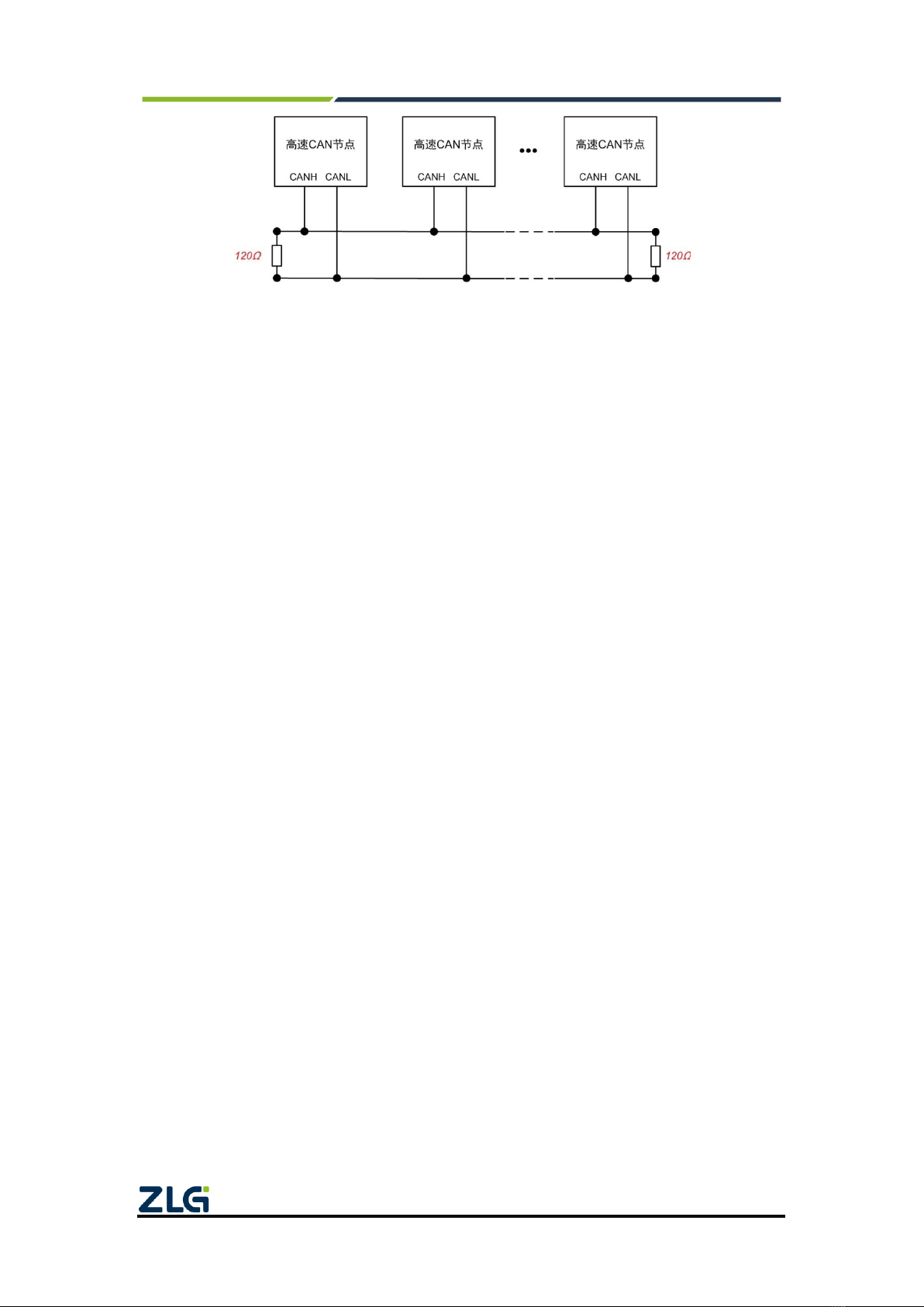
Supports setting the 120-ohm terminal resistance switch at both ends of the CAN (FD)
channel;
Supports setting the receiving hardware filtering function of CAN (FD) channels at
both ends. Each channel supports 64 standard/extended frame IDs. The filtering
method is whitelist filtering, which minimizes the load of the CAN bus;
When using USB to connect the device to the computer, you can enable the function
of automatically reporting and recording the current error status and error count
(sending and receiving error counts) of the CAN (FD) channels at both ends by using
the CANFDBridge configuration tool. It can be used as a very practical CAN network
status analyzer, which quickly determines the CAN communication quality;
Supports CAN (FD) message forwarding, including three forwarding modes: (1) basic
forwarding; (2) frame mapping; (3) grouping and unpacking. The forwarding function
is mainly for received CAN(FD) frames. Before forwarding, the received frames are
processed such as mapping, grouping and unpacking, and the processed frames are
sent. The processing priority is: grouping and unpacking > frame mapping > basic
forwarding;
After forwarding fails, return the specified frame to tell the sender that the forwarding
failed;
In the case of relaying, the CAN single-channel standard frame rate can reach 6,000

CANFDNET-400U
High-performance Four-channel CANFD Bus-to-Ethernet Converter User Manual
©2021 Guangzhou ZLG Microelectronics Technology Corp.,Ltd.
2
User Manual
frames/s, and the CANFD single-channel standard frame rate can reach 4,600
frames/s;
When only the relay is used, the forwarding delay is about 40 us. When frame
mapping and merging and splitting functions are used at the same time, the
forwarding delay is about 50 us. The more frame mapping, merging and splitting rules,
the greater the forwarding delay. The forwarding delay is also affected by the baud
rate. When the baud rate value is small, such as 50 kbps, the forwarding delay is up
to 60 us;
The CAN-bus circuit adopts 2,500 V DC electrical isolation;
Can be used in environments with safety and explosion-proof requirements;
Operating temperature: -40℃to +85℃; Operating power: less than 2 W;
1.3 Typical Applications
Coal mine telecommunication;
Industrial site control;
Remote monitoring and data collection;
Electrical communication;

CANFDNET-400U
High-performance Four-channel CANFD Bus-to-Ethernet Converter User Manual
©2021 Guangzhou ZLG Microelectronics Technology Corp.,Ltd.
3
User Manual
2. Hardware
2.1 Appearance and Installation Dimensions
Figure 2.1 and Figure 2.2 show the appearance and installation dimensions.
Figure 2.1 CANFDBridge appearance (without mounting ears)

CANFDNET-400U
High-performance Four-channel CANFD Bus-to-Ethernet Converter User Manual
©2021 Guangzhou ZLG Microelectronics Technology Corp.,Ltd.
4
User Manual
Figure 2.2 CANFDBridge installation dimensions
2.2 Power Supply and USB Interface
CANFDBridge has two power supply methods. The first is powered via USB and the
second is powered via DC power. It can work with any power supply method. An external
power supply and a USB cable are also possible, but it is recommended to use the USB
power supply method when you configure the device, and DC power supply in other cases.
The USB cable is type B (square port), and a USB cable is provided before delivery. Table
2.1 lists the pin definitions of the DC power interface.
Table 2.1 Interface description
Type
Schematic Diagram
Pin definitions
Pin description
OPEN3
1: GND
Power input negative
2: EARTH
Ground
3: 9V-48V
Power input positive
2.3 CAN(FD) Communication Interface
CANFDBridge has two CAN(FD)-bus interfaces. Table 2.2 lists the interface pin
definitions.

CANFDNET-400U
High-performance Four-channel CANFD Bus-to-Ethernet Converter User Manual
©2021 Guangzhou ZLG Microelectronics Technology Corp.,Ltd.
5
User Manual
Table 2.2 CAN interface definitions
Type
Schematic Diagram
Pin definitions
Pin description
DB9 socket
1: NC
Dangling
2: CAN_L
CAN data transceiving
differential inverted signal
3, 6: CAN_GND
CAN isolated ground
4, 8: NC
Dangling
5: Shield
Shielding ground
7: CAN_H
CAN data sending and
receiving differential
positive phase signal
9: NC
Dangling
DB9 socket
1: NC
Dangling
2: CAN_L
CAN data transceiving
differential inverted signal
3, 6: CAN_GND
CAN isolated ground
4, 8: NC
Dangling
5: Shield
Shielding ground
7: CAN_H
CAN data sending and
receiving differential
positive phase signal
9: NC
Dangling
2.4 Indicators
CANFDBridge has four red and green bi-color LEDs to indicate its operating status.
Table 2.3 lists the functions.
Table 2.3 LED indicators
Indicator
STATUS
Indication status
SYS indicator
Green
Power on equipment
Off
The device is not powered on
Green flashing
Device running
USB indicator light
Off
USB cable not connected
Always red
USB cable connected but driver not installed
Green normally on
The USB driver has been installed, and the USB
cable has been connected
Green flashing
The USB is communicating with the device
Flash in red
USB and device communication error

CANFDNET-400U
High-performance Four-channel CANFD Bus-to-Ethernet Converter User Manual
©2021 Guangzhou ZLG Microelectronics Technology Corp.,Ltd.
6
User Manual
CANFD
Channel indicator
(Channel 0, Channel 1)
Green normally on
The CAN channel is idle
Green flashing
The CAN channel is sending/receiving data
Flash in red
CAN channel bus error
2.5 CAN Bus Connection
The physical layer mainly transmits inter-device signals, converts various information
into transmittable physical signals (usually electrical or optical signals), and transmits
these signals to other target devices. For this purpose, CAN-bus has made detailed
regulations on signal levels, cables and connectors used for communication.
Two standards are released after CAN-bus was standardized by ISO, namely
ISO11898-2 (125kbps-1Mbps high-speed communication standard) and ISO11898-3
(low-speed communication standard less than 125 kbps).
The CAN transceiver determines the bus level based on the voltage difference
between the two cables. This transmission method is called differential transmission.
There are only two possibilities for the level signal transmitted on the cable, namely the
dominant level and the recessive level. The dominant level indicates logic 0, and the
recessive level indicates logic 1. Table 2.4 lists the high-speed CAN electrical
characteristics.
Table 2.4 CAN-BUS interface specifications
parameter
Minimum
Typical
value
Maximum
Unit
Communication baud rate
5k
1M
bps
Number of nodes
110
pcs
Dominant level (logic 0)
CANH
2.75
3.5
4.5
V
CANL
0.5
1.5
2.25
Recessive level (logic 1)
CANH
2
2.5
3
CANL
2
2.5
3
Differential level
Dominant (logic 0)
1.5
2
3.0
Recessive (logic 1)
-0.5
0
0.05
Maximum withstand voltage
of the bus pin
-18
18
Instantaneous voltage of
the bus
-100
+100
Isolation voltage (DC)
2500
V
The CAN bus adopts balanced transmission. ISO11898-2 stipulates: In the
high-speed CAN, a 120 ohm terminal resistor needs to be connected to the network
terminal node to eliminate signal reflection on the bus and avoid signal distortion. Figure
2.3 shows the high-speed CAN network topology.
The device has a built-in 120 ohm terminal resistance, which can be configured to
turn on or off by using the CANCfg configuration tool.

CANFDNET-400U
High-performance Four-channel CANFD Bus-to-Ethernet Converter User Manual
©2021 Guangzhou ZLG Microelectronics Technology Corp.,Ltd.
7
User Manual
Figure 2.3 High-speed CAN topology
Note: The bus communication distance and communication rate are related to the field application and
can be designed according to the actual application and related standards. The CAN-Bus cable can use
ordinary twisted pair, shielded twisted pair or standard bus communication cable. In long-distance
communication, the terminal resistance value needs to be selected according to the communication
distance, cable impedance and number of nodes.

CANFDNET-400U
High-performance Four-channel CANFD Bus-to-Ethernet Converter User Manual
©2021 Guangzhou ZLG Microelectronics Technology Corp.,Ltd.
8
User Manual
3. Driver and Configuration Tool Installation
After CANFDBridge is connected to the computer using the USB Type-B cable, use
the CANCfg software to configure the parameters. Therefore, install CANFDBridge driver
and CANCfg host computer software before using CANFDBridge. This document uses a
computer running Windows 7 as an example to describe how to install the CANFDBridge
driver and CANCfg host computer software and describe the operation of the CANCfg
software.
3.1 Installing the Driver on Windows
First, connect the CANFDBridge device to the computer with a USB cable to
ensure that the device is powered properly. Right-click [Computer] and choose
[Properties] (as shown in Figure 3.1) to open the Device Manager. Before the driver is
installed, the Device Manager is displayed, as shown in Figure 3.2. At this time, if the
device manager does not display the message, check whether the USB cable is
connected correctly, whether the USB port of the computer is disabled, and whether
the device indicator USB is on.
Figure 3.1 Opening the computer device manager

CANFDNET-400U
High-performance Four-channel CANFD Bus-to-Ethernet Converter User Manual
©2021 Guangzhou ZLG Microelectronics Technology Corp.,Ltd.
9
User Manual
Figure 3.2 No driver installed
Right-click [CANFDBridge] and choose [Update Driver Software]. The update
driver software interface appears, as shown in Figure 3.3.
Figure 3.3 Updating the driver
As shown in Figure 3.4, in the pop-up interface, click [Browse], select the official
CANFDBridge driver folder, click [Next], and wait until the driver is installed.

CANFDNET-400U
High-performance Four-channel CANFD Bus-to-Ethernet Converter User Manual
©2021 Guangzhou ZLG Microelectronics Technology Corp.,Ltd.
10
User Manual
Figure 3.4 Installing the driver
After the installation is complete, the message "The driver file has been
successfully updated" appears. Click the [Close] button to complete the installation, as
shown in Figure 3. 5.
Figure 3.5 Driver installation complete
After driver installation, is displayed in the device manager,
which indicates that the driver is installed correctly, and the device USB indicator
changes from red to green. At this time, the CANFDBridge and PC have been

CANFDNET-400U
High-performance Four-channel CANFD Bus-to-Ethernet Converter User Manual
©2021 Guangzhou ZLG Microelectronics Technology Corp.,Ltd.
11
User Manual
connected, and the CANFDBridge can be configured by using the CANCfg host
computer software.
3.2 Installing the Software CANCfg on the PC
CANCfg software is the company's CAN-Hub and CAN-Bridge equipment-specific
configuration software running on the Windows platform. You can obtain and change the
configuration parameters of the CANFDBridge device and upgrade the device firmware by
using the CANCfg software.
3.2.1 Configuration Tool Installation Example
You can download the latest version of CANCfg software from the official website of
ZLG Electronics www.zlg.cn by searching for "CAN networking equipment configuration
tool". Double-click the unzipped CANCfgSetup.exe file. The welcome window appears, as
shown in Figure 3.6. Click [Next] to install.
Figure 3.6 Welcome interface
The window shown in Figure 3.7 appears. The window asks for the installation path
(The default installation path is C:\Program Files(x86)\CANCfg). To change the installation
path, click [Browse].

CANFDNET-400U
High-performance Four-channel CANFD Bus-to-Ethernet Converter User Manual
©2021 Guangzhou ZLG Microelectronics Technology Corp.,Ltd.
12
User Manual
Figure 3.7 Selecting an installation path
Click [Install] to install the file in the installation path. After the installation is complete,
the successful installation message as shown in Figure 3.8 will appear. Click [Finish] to
exit the installation software.
Figure 3.8 Installation complete

CANFDNET-400U
High-performance Four-channel CANFD Bus-to-Ethernet Converter User Manual
©2021 Guangzhou ZLG Microelectronics Technology Corp.,Ltd.
13
User Manual
4. Quick Instructions
This chapter describes the operation of the CANFDBridge device by using the
CANCfg software to help you get familiar with the product.
4.1 Obtaining Basic Device Information
Double-click to run the CANCfg software. Figure 4.1 shows the software
interface.
Figure 4.1 CANCfg running interface
Click the CANFDBridge in the left device type. The CANFDBridge configuration
interface appears, as shown in Figure 4.2.

CANFDNET-400U
High-performance Four-channel CANFD Bus-to-Ethernet Converter User Manual
©2021 Guangzhou ZLG Microelectronics Technology Corp.,Ltd.
14
User Manual
Figure 4.2 CANFDBridge basic information
After connecting the device, you can click to get the device information.
Figure 4.3 shows the information obtained by using the device this time. If the information
cannot be obtained, the device may not be properly connected to the computer. Check
whether the device USB indicator is solid red. If yes, the connection to the computer is
abnormal, or the driver is not installed.
Figure 4.3 Obtaining the CANFDBridge device information
4.2 Managing Device Configurations
On the CANFDBridge basic information interface, the four buttons in the configuration
part indicate:
Get device configuration] means to obtain all configuration parameters of the device
from the current device. Click this button to display the current device configurations,
including the baud rate, filtering, relaying, failback, frame mapping, merging and splitting.
[Configure device] means to write the configuration parameters in the window such as
baud rate, filtering, relay, failback, frame mapping, merging and splitting into the device.
The configuration takes effect immediately after being written.

CANFDNET-400U
High-performance Four-channel CANFD Bus-to-Ethernet Converter User Manual
©2021 Guangzhou ZLG Microelectronics Technology Corp.,Ltd.
15
User Manual
[Load configurations from files] Load configurations from the previously saved
configuration file into the baud rate, filter, relay, failback, frame map, merge and split
windows. To configure to a device, click the [Configure Device] button.
[Save configurations to files] Save the current baud rate, filtering, relay, failback,
frame mapping, merging and splitting and other window parameters to a file, which
facilitates next use or other devices.
4.3 Configuring Parameters
4.3.1 CAN
The CAN window is used to configure the two channel parameters of CANFDBridge,
such as baud rate, CAN controller type, and termination resistance enable, as shown in
Figure 4.4.
Figure 4.4 Baud rate
Each channel supports setting the controller type, as shown in Figure 4.5. When the
selected type is CAN, only CAN messages can be sent and received. You can set the port
controller type connected to the CAN bus to CAN to prevent CANFD messages from
being forwarded to the CAN bus. When the selected type is CANFD, both CAN messages
and CANFD messages can be sent and received.
Figure 4.5 Controller types
Each channel supports setting the CANFD protocol standard, as shown in Figure 4.6.
Both ISO and Non-ISO standards are supported.

CANFDNET-400U
High-performance Four-channel CANFD Bus-to-Ethernet Converter User Manual
©2021 Guangzhou ZLG Microelectronics Technology Corp.,Ltd.
16
User Manual
Figure 4.6 CANFD protocol
Each channel can choose to enable or disable the internal termination resistor. To
enable the resistor, select ; if this check box is not selected, the internal
terminating resistor is disabled.
Each channel supports setting the baud rate. Figure 4.7 shows the setting interface.
The baud rate option includes the arbitration domain baud rate and the data domain baud
rate. For an ordinary CAN, the baud rate is determined by the arbitration domain baud rate,
and the data domain baud rate is invalid. For CANFD, the data domain baud rate is valid
only when acceleration is enabled. CAN bus baud rate. In addition to the standard baud
rates recommended by CIA (75-83.5% sampling point, SJW = 2, 3) in the list, a "custom"
option is also given.Select a custom baud rate, click [Calculator] to call the baud rate
calculator to calculate the desired baud rate, copy the calculated baud rate, and enter the
value in the custom baud rate box.
Figure 4.7 Baud rate settings
The baud rate calculator method is as follows:
1. As shown in Figure 4.8, set the arbitration domain baud in ①, select the
appropriate synchronization jump width, and select the required baud rate. Enter
a value manually if the drop-down list does not have your desired value;
2. Set the data domain baud rate in ②, select an appropriate synchronization jump
width, and select the required baud rate. Enter a value manually if the drop-down

CANFDNET-400U
High-performance Four-channel CANFD Bus-to-Ethernet Converter User Manual
©2021 Guangzhou ZLG Microelectronics Technology Corp.,Ltd.
17
User Manual
list does not have your desired value;
3. After setting, click the calculation button at ③to list the calculation results of the
corresponding baud rate for your choice;
4. Select the arbitration domain baud rate for the appropriate sampling point. If the
value is selected, the blue background color appears, indicating that the value is
selected, as shown in ④;
5. Select the data domain baud rate for the appropriate sampling point. If the value
is selected, the blue background color appears, indicating that the value is
selected, as shown in ⑤;
6. Click the copy button at ⑥to copy the custom baud rate, and paste this value
into the custom baud rate text box.
Figure 4.8 Using the baud rate calculator
Advanced settings are available for each channel. Click to display the
advanced setting interface, as shown in Figure 4.9. In the advanced settings, set the
channel forwarding mode and failback function.
Table of contents
Popular Network Hardware manuals by other brands

ICP CON
ICP CON PPDS-700-MTCP Series quick start

ICP DAS USA
ICP DAS USA I-2533CS Series user manual

MikroTik
MikroTik RouterBOARD 711-5HnD Quick setup guide and warranty information

ADTRAN
ADTRAN 1442702PG1 quick start guide

Brickcom
Brickcom NR-1100 series user manual

D-Link
D-Link MYDLINK DNR-322L Quick install guide