4
BEFORE INSTALLATION
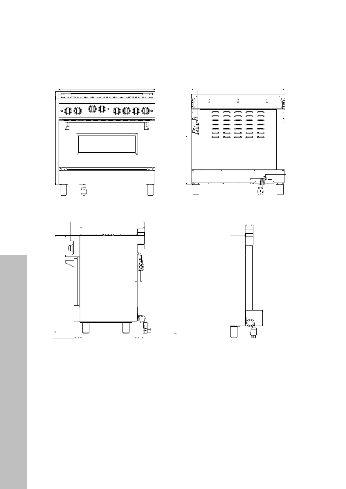
PRODUCT DIMENSIONS
4"
D
E
B
A
C
43
Please keep this manual for future use.
The rating tag shows the model and serial number of your range. The tag is located under
the front edge of the range cooktop. The tag is visible when the oven door is open. Do not
remove permanently affixed labels, warnings, or plates from the product. This will void the
warranty.
WARRANTY AND SERVICE
All range products carry a one year parts warranty and includes service, if required.
Service on all products shall be carried out by industry professionals only. For warranty
service, please call customer service.
REPLACEMENT PARTS
Only authorized replacement parts may be used in performing service on this appliance.
Replacement parts are available from ZLINE. Call 1-614-777-5004.
WARRANTY AND SERVICE
Appliance Tag Here
Warranty and Service
BEFORE INSTALLATION
Product Dimensions
WARRANTY AND SERVICE
Warranty and Service
“A” will change with size of range (24”-48”).
δε
A
32"1/8 (816)
δε
δε
δε
δε
δε
δε
δε δε δε
32 “
1
/8
A
2“
1
/8
“
3
/16
2“
9
/16
2“
3
/4
27 “
7
/16
7“
7
/8
36”
2“
3
/16 21 “
1
/8
1“
1
/4
δε
A
32"1/8 (816)
δε
δε
δε
δε
δε
δε
δε δε δε
32 “
1
/8
A
2“
1
/8
“
3
/16
2“
9
/16
2“
3
/4
27 “
7
/16
7“
7
/8
36”
2“
3
/16 21 “
1
/8
1“
1
/4
5"9/16 (140)
7"13/16(198.5)
2"3/16 (55)
δε
δε
δε A
3 “
15
/
16
2 “
5
/
16
18 “
13
/
16
5“
9
/
16
7“
13/
16
2“
3
/
16
δε
A
32"1/8 (816)
δε
δε
δε
δε
δε
δε
δε δε δε
32 “
1
/8
A
2“
1
/8
“
3
/16
2“
9
/16
2“
3
/4
27 “
7
/16
7“
7
/8
36”
2“
3
/16 21 “
1
/8
1“
1
/4
43
Please keep this manual for future use.
The rating tag shows the model and serial number of your range. The tag is located under
the front edge of the range cooktop. The tag is visible when the oven door is open. Do not
remove permanently affixed labels, warnings, or plates from the product. This will void the
warranty.
WARRANTY AND SERVICE
All range products carry a one year parts warranty and includes service, if required.
Service on all products shall be carried out by industry professionals only. For warranty
service, please call customer service.
REPLACEMENT PARTS
Only authorized replacement parts may be used in performing service on this appliance.
Replacement parts are available from ZLINE. Call 1-614-777-5004.
WARRANTY AND SERVICE
Appliance Tag Here
Warranty and Service
BEFORE INSTALLATION
Product Dimensions
WARRANTY AND SERVICE
Warranty and Service
“A” will change with size of range (24”-48”).
δε
A
32"1/8 (816)
δε
δε
δε
δε
δε
δε
δε δε δε
32 “
1
/8
A
2“
1
/8
“
3
/16
2“
9
/16
2“
3
/4
27 “
7
/16
7“
7
/8
36”
2“
3
/16 21 “
1
/8
1“
1
/4
δε
A
32"1/8 (816)
δε
δε
δε
δε
δε
δε
δε δε δε
32 “
1
/8
A
2“
1
/8
“
3
/16
2“
9
/16
2“
3
/4
27 “
7
/16
7“
7
/8
36”
2“
3
/16 21 “
1
/8
1“
1
/4
5"9/16 (140)
7"13/16(198.5)
2"3/16 (55)
δε
δε
δε A
3 “
15
/
16
2 “
5
/
16
18 “
13
/
16
5“
9
/
16
7“
13/
16
2“
3
/
16
δε
A
32"1/8 (816)
δε
δε
δε
δε
δε
δε
δε δε δε
32 “
1
/8
A
2“
1
/8
“
3
/16
2“
9
/16
2“
3
/4
27 “
7
/16
7“
7
/8
36”
2“
3
/16 21 “
1
/8
1“
1
/4
(70 mm)
F
43
Please keep this manual for future use.
The rating tag shows the model and serial number of your range. The tag is located under
the front edge of the range cooktop. The tag is visible when the oven door is open. Do not
remove permanently affixed labels, warnings, or plates from the product. This will void the
warranty.
WARRANTY AND SERVICE
All range products carry a one year parts warranty and includes service, if required.
Service on all products shall be carried out by industry professionals only. For warranty
service, please call customer service.
REPLACEMENT PARTS
Only authorized replacement parts may be used in performing service on this appliance.
Replacement parts are available from ZLINE. Call 1-614-777-5004.
WARRANTY AND SERVICE
Appliance Tag Here
Warranty and Service
BEFORE INSTALLATION
Product Dimensions
WARRANTY AND SERVICE
Warranty and Service
“A” will change with size of range (24”-48”).
δε
A
32"1/8 (816)
δε
δε
δε
δε
δε
δε
δε δε δε
32 “
1
/8
A
2“
1
/8
“
3
/16
2“
9
/16
2“
3
/4
27 “
7
/16
7“
7
/8
36”
2“
3
/16 21 “
1
/8
1“
1
/4
δε
A
32"1/8 (816)
δε
δε
δε
δε
δε
δε
δε δε δε
32 “
1
/8
A
2“
1
/8
“
3
/16
2“
9
/16
2“
3
/4
27 “
7
/16
7“
7
/8
36”
2“
3
/16 21 “
1
/8
1“
1
/4
5"9/16 (140)
7"13/16(198.5)
2"3/16 (55)
δε
δε
δε A
3 “
15
/
16
2 “
5
/
16
18 “
13
/
16
5“
9
/
16
7“
13/
16
2“
3
/
16
δε
A
32"1/8 (816)
δε
δε
δε
δε
δε
δε
δε δε δε
32 “
1
/8
A
2“
1
/8
“
3
/16
2“
9
/16
2“
3
/4
27 “
7
/16
7“
7
/8
36”
2“
3
/16 21 “
1
/8
1“
1
/4
21 1/4" (540 mm)2 1/8" (54 mm)
36 1/8" (816 mm)
1 1/4" (32 mm)
27 1/2" (699 mm)
24" (610 mm)
A
2 1/2"
(64 mm)
32 1/8" (816 mm)
43
Please keep this manual for future use.
The rating tag shows the model and serial number of your range. The tag is located under
the front edge of the range cooktop. The tag is visible when the oven door is open. Do not
remove permanently affixed labels, warnings, or plates from the product. This will void the
warranty.
WARRANTY AND SERVICE
All range products carry a one year parts warranty and includes service, if required.
Service on all products shall be carried out by industry professionals only. For warranty
service, please call customer service.
REPLACEMENT PARTS
Only authorized replacement parts may be used in performing service on this appliance.
Replacement parts are available from ZLINE. Call 1-614-777-5004.
WARRANTY AND SERVICE
Appliance Tag Here
Warranty and Service
BEFORE INSTALLATION
Product Dimensions
WARRANTY AND SERVICE
Warranty and Service
“A” will change with size of range (24”-48”).
δε
A
32"1/8 (816)
δε
δε
δε
δε
δε
δε
δε δε δε
32 “
1
/8
A
2“
1
/8
“
3
/16
2“
9
/16
2“
3
/4
27 “
7
/16
7“
7
/8
36”
2“
3
/16 21 “
1
/8
1“
1
/4
δε
A
32"1/8 (816)
δε
δε
δε
δε
δε
δε
δε δε δε
32 “
1
/8
A
2“
1
/8
“
3
/16
2“
9
/16
2“
3
/4
27 “
7
/16
7“
7
/8
36”
2“
3
/16 21 “
1
/8
1“
1
/4
5"9/16 (140)
7"13/16(198.5)
2"3/16 (55)
δε
δε
δε A
3 “
15
/
16
5
/
16
18 “
13
/
16
5“
9
/
16
7“
13/
16
2“
3
/
16
δε
A
32"1/8 (816)
δε
δε
δε
δε
δε
δε
δε δε δε
32 “
1
/8
A
2“
1
/8
“
3
/16
2“
9
/16
2“
3
/4
27 “
7
/16
7“
7
/8
36”
2“
3
/16 21 “
1
/8
1“
1
/4
43
Please keep this manual for future use.
The rating tag shows the model and serial number of your range. The tag is located under
the front edge of the range cooktop. The tag is visible when the oven door is open. Do not
remove permanently affixed labels, warnings, or plates from the product. This will void the
warranty.
WARRANTY AND SERVICE
All range products carry a one year parts warranty and includes service, if required.
Service on all products shall be carried out by industry professionals only. For warranty
service, please call customer service.
REPLACEMENT PARTS
Only authorized replacement parts may be used in performing service on this appliance.
Replacement parts are available from ZLINE. Call 1-614-777-5004.
WARRANTY AND SERVICE
Appliance Tag Here
Warranty and Service
BEFORE INSTALLATION
Product Dimensions
WARRANTY AND SERVICE
Warranty and Service
“A” will change with size of range (24”-48”).
δε
A
32"1/8 (816)
δε
δε
δε
δε
δε
δε
δε δε δε
32 “
1
/8
A
2“
1
/8
“
3
/16
2“
9
/16
2“
3
/4
27 “
7
/16
7“
7
/8
36”
2“
3
/16 21 “
1
/8
1“
1
/4
δε
A
32"1/8 (816)
δε
δε
δε
δε
δε
δε
δε δε δε
32 “
1
/8
A
2“
1
/8
“
3
/16
2“
9
/16
2“
3
/4
27 “
7
/16
7“
7
/8
36”
2“
3
/16 21 “
1
/8
1“
1
/4
5"9/16 (140)
7"13/16(198.5)
2"3/16 (55)
δε
δε
δε A
3 “
15
/
16
2 “
5
/
16
18 “
13
/
16
5“
9
/
16
7“
13/
16
2“
3
/
16
δε
A
32"1/8 (816)
δε
δε
δε
δε
δε
δε
δε δε δε
32 “
1
/8
A
2“
1
/8
“
3
/16
2“
9
/16
2“
3
/4
27 “
7
/16
7“
7
/8
36”
2“
3
/16 21 “
1
/8
1“
1
/4
21 1/4" (540 mm)2 1/8" (54 mm)
36 1/8" (816 mm)
1 1/4" (32 mm)
27 1/2" (699 mm)
24" (610 mm)
7 7/8"
(200 mm)
2 1/2"
(64 mm)
32 1/8" (816 mm)
2 1/2" (64 mm)
43
Please keep this manual for future use.
The rating tag shows the model and serial number of your range. The tag is located under
the front edge of the range cooktop. The tag is visible when the oven door is open. Do not
remove permanently affixed labels, warnings, or plates from the product. This will void the
warranty.
WARRANTY AND SERVICE
All range products carry a one year parts warranty and includes service, if required.
Service on all products shall be carried out by industry professionals only. For warranty
service, please call customer service.
REPLACEMENT PARTS
Only authorized replacement parts may be used in performing service on this appliance.
Replacement parts are available from ZLINE. Call 1-614-777-5004.
WARRANTY AND SERVICE
Appliance Tag Here
Warranty and Service
BEFORE INSTALLATION
Product Dimensions
WARRANTY AND SERVICE
Warranty and Service
“A” will change with size of range (24”-48”).
δε
A
32"1/8 (816)
δε
δε
δε
δε
δε
δε
δε δε δε
32 “
1
/8
A
2“
1
/8
“
3
/16
2“
9
/16
2“
3
/4
27 “
7
/16
7“
7
/8
36”
2“
3
/16 21 “
1
/8
1“
1
/4
δε
A
32"1/8 (816)
δε
δε
δε
δε
δε
δε
δε δε δε
32 “
1
/8
A
2“
1
/8
“
3
/16
2“
9
/16
2“
3
/4
27 “
7
/16
7“
7
/8
36”
2“
3
/16 21 “
1
/8
1“
1
/4
5"9/16 (140)
7"13/16(198.5)
2"3/16 (55)
δε
δε
δε A
3 “
15
/
16
5
/
16
18 “
13
/
16
5“
9
/
16
7“
13/
16
2“
3
/
16
δε
A
32"1/8 (816)
δε
δε
δε
δε
δε
δε
δε δε δε
32 “
1
/8
A
2“
1
/8
“
3
/16
2“
9
/16
2“
3
/4
27 “
7
/16
7“
7
/8
36”
2“
3
/16 21 “
1
/8
1“
1
/4
43
Please keep this manual for future use.
The rating tag shows the model and serial number of your range. The tag is located under
the front edge of the range cooktop. The tag is visible when the oven door is open. Do not
remove permanently affixed labels, warnings, or plates from the product. This will void the
warranty.
WARRANTY AND SERVICE
All range products carry a one year parts warranty and includes service, if required.
Service on all products shall be carried out by industry professionals only. For warranty
service, please call customer service.
REPLACEMENT PARTS
Only authorized replacement parts may be used in performing service on this appliance.
Replacement parts are available from ZLINE. Call 1-614-777-5004.
WARRANTY AND SERVICE
Appliance Tag Here
Warranty and Service
BEFORE INSTALLATION
Product Dimensions
WARRANTY AND SERVICE
Warranty and Service
“A” will change with size of range (24”-48”).
δε
A
32"1/8 (816)
δε
δε
δε
δε
δε
δε
δε δε δε
32 “
1
/8
A
2“
1
/8
“
3
/16
2“
9
/16
2“
3
/4
27 “
7
/16
7“
7
/8
36”
2“
3
/16 21 “
1
/8
1“
1
/4
δε
A
32"1/8 (816)
δε
δε
δε
δε
δε
δε
δε δε δε
32 “
1
/8
A
2“
1
/8
“
3
/16
2“
9
/16
2“
3
/4
27 “
7
/16
7“
7
/8
36”
2“
3
/16 21 “
1
/8
1“
1
/4
5"9/16 (140)
7"13/16(198.5)
2"3/16 (55)
δε
δε
δε A
3 “
15
/
16
2 “
5
/
16
18 “
13
/
16
5“
9
/
16
7“
13/
16
2“
3
/
16
δε
A
32"1/8 (816)
δε
δε
δε
δε
δε
δε
δε δε δε
32 “
1
/8
A
2“
1
/8
“
3
/16
2“
9
/16
2“
3
/4
27 “
7
/16
7“
7
/8
36”
2“
3
/16 21 “
1
/8
1“
1
/4
NOTE: The above diagram is of the RG36 series range; the measurements listed without a
letter are universal across all RG models. See the next page for dimensions by model, and
for in-depth product and cutout dimensions, see pages 10–11.
Product Dimensions