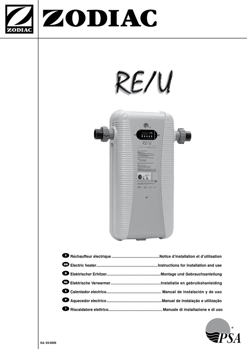
Zodiac Heat Line 20 User manual

H0360800.D - 2016/02
Instruc ons for installa on and use
English
More documents on:
www.zodiac-poolcare.com
Heat Line
EN

1H0360800.D - EN - 2016-02
WARNINGS
• Failure to respect the warnings may cause serious damage to the pool equipment or cause serious injury,
even death.
• The appliance is intended for a specifi c pool use and must not be used for any use other than that for which
it was designed.
• It is important that the equipment is operated by competent and qualifi ed (both physically and mentally)
people who have previously received the instruc ons for use. All persons not mee ng these criteria must not
approach the appliance in order to avoid exposure to dangerous elements.
• Keep the appliance out of the reach of children.
• The device must be installed by a qualifi ed technician according to the manufacturer’s instruc ons and
in compliance with local regula ons. The installer is responsible for installa on of the equipment and for
compliance with na onal installa on regula ons. Under no circumstances can the manufacturer be held
liable in the event of failure to comply with applicable local standards.
• Incorrect installa on and/or use may cause serious damage to property or serious injuries (possibly causing
death).
• All equipment, even postage and packing paid, travels at the risks and perils of the recipient. The consignee
shall make reserva ons in wri ng on the carrier's bill of lading if damage is detected, caused during transport
(confi rma on to be sent to the carrier within 48 hours by registered mail with acknowledgement of receipt).
In the event of a device containing coolant that has been turned on its side, men on your reserva ons in
wri ng to the carrier.
• If the appliance suff ers a malfunc on, do not try to repair the appliance yourself, contact a qualifi ed technician.
• Refer to the warranty condi ons for details of the permi ed water balance values for opera ng the appliance.
• Elimina ng or shun ng one of the safety devices automa cally voids the warranty, as does the replacement
of parts using parts not manufactured by ourselves.
• Do not spray insec cide or any other chemical (infl ammable or non-infl ammable) in the direc on of the
appliance, as this may damage the body and cause a fi re.
• The electrical supply to the appliance must be protected by a dedicated 30 mA diff eren al residual current
protec on device, complying with the standards and regula ons in force in the country where it is installed.
• Before carrying out any opera ons, check that:
-The voltage indicated on the maker's plate of the appliance corresponds to the mains voltage,
-The power grid is adapted to the power requirements of the appliance, and is grounded.
-The plug (where applicable) is suitable for the socket.
• In the event of abnormal func on or the release of odours from the appliance, turn it of immediately, unplug
it from its power supply and contact a professional.
• Before any interven on on the appliance, ensure that the la er is switched off and disconnected from the
power supply, in addi on to any other equipment connected to the appliance, and that the hea ng priority
(where applicable) is deac vated.
• Do not disconnect and reconnect the appliance to the power supply when in opera on.
• Do not pull on the power cord to disconnect it from the power supply.
• Do not handle the electrical elements with wet hands.
• Clean the terminal board or the power supply socket before connec on.
• For any component or sub-assembly containing a ba ery: do not recharge or dismantle the ba ery, or throw
it into a fi re. Do not expose it to high temperatures or direct sunlight.
• In stormy weather, unplug the appliance to prevent it from suff ering lightning damage.
• Do not immerse the appliance in water (with the excep on of cleaners) or mud.
Recycling
This symbol means that your appliance must not be thrown into a normal bin. It will be selec vely collected for the
purpose of reuse, recycling or transforma on. If it contains any substances that may be harmful to the environment,
these will be eliminated or neutralised.
Contact your dealer for recycling informa on.
EN

H0360800.D - EN - 2016-022
CONTENTS
❶ Specifi ca ons 3
1.1 I Descrip on 3
1.2 I Technical specifi ca ons 3
1.3 I Dimensions and marking 4
❷ Installa on 5
2.1 I Selec ng the loca on 5
2.2 I Hydraulic connec ons 6
2.3 I Electricity supply connec ons (depending on the models) 7
❸ Use 8
3.1 I Opera ng principle 8
3.2 User interface presenta on (depending on the models) 8
3.3 I Opera ng 9
3.4 I Addi onal func ons 10
❹ Maintenance 11
4.1 I Wintering 11
4.2 I Maintenance 11
❺ Troubleshoo ng 12
5.1 I Device behaviour 12
5.2 I Error code display 13
5.3 I Replacing the electrical box fuse (depending on the models) 13
5.4 I Wiring diagram 13
• Before you do anything with the device, it is vital that you read this installa on and user
manual, as well as the "warnings and warranty" booklet delivered with the device. Failure to
do so may result in material damage or serious or fatal injury and will invalidate the warranty.
• Keep and pass on these documents for later consulta on during the device's life me.
• It is prohibited to distribute or modify this document in any way without authorisa on from
Zodiac®.
• Zodiac® is constantly developing its products to improve their quality; therefore, the
informa on contained in this document may be modifi ed without no ce.
Tip: to make it easier to contact your reseller
• Write down your reseller's contact details to help you fi nd them more easily and fi ll in the "product"
informa on on the back of the manual; your reseller will ask you for this informa on.

3H0360800.D - EN - 2016-02
❶ Specifi ca ons
1.1 I Descrip on
or or
AHeat Line +
BHeat Line without circula ng pump (SC)
C Bare Heat Line N
1.2 I Technical specifi ca ons
Heat Line Unit 20 40 70
Primary °C 90 45 90 45 90 45
Secondary °C 26 26 26
Power kW 20 440870 14
Flow rate Primary m³/h 0.9 0.7 1.7 1.4 32.4
Secondary 10 15 20
Head loss Primary bar 0.015 0.02 0.03
Secondary 0.05 0.08 0.1
Primary connec on Ø 26/34 female, screw type (Heat Line + and SC)
Ø 26/34 male, screw type (Heat Line N)
Secondary connec on PVC Ø50 or Ø63
Protec on index IP44 (Heat Line + only)
Opera ng
temperature
range
Pool water 2 to 40 °C
Primary circuit
water 45 to 90 °C
Primary circuit
pressure
Service 2 bars
maximum 3 bars
1.2.1 Heat Line + circula ng pump characteris cs
Heat Line + Circula ng pump Spacer Absorbed power In
Speed 3
20-40-70 UPM3 25/50 - 130 130 mm. 33 W 0.15 A
EN

H0360800.D - EN - 2016-024
1.3 I Dimensions and marking
Front
Heat Line 20-40 70
535 mm 665 mm
198 mm 328 mm
Heat Line + SC N
Mul -tube exchanger body
½ union PVC connector Ø63 to be
glued
Primary circuit drainage cap
Glove fi nger
Regula on sensor
Circula ng pump
Exchanger body a achment
Electrical unit
Male/male Ø26/34 nipple
An -return valve
Cap
Booster + fl ow controller

5H0360800.D - EN - 2016-02
❷ Installa on
2.1 I Selec ng the loca on
• The appliance must be installed in a technical room ven lated, dry and without stored pool
treatment products.
• Install the appliance as close as possible to the hea ng source (boiler, heat pump, geothermal, solar-powered hea ng,
etc.),
• If the appliance cannot be installed beside the hea ng source:
- Provide for the dimensioning of the pipes and primary and secondary circuits in rela on to the water fl ow rate, the
losses of load and the distance, and insulate them thermally,
- Install a more powerful circula ng pump (contact us for its dimensions and supply),
• If the exchanger is located far from the fi lter: The pipes of the pool system must be Ø50, or Ø63 if the system has an
overall length in excess of 30 meters, and must be routed through a protec ve conduit if buried.
• Preferably, the exchanger should be installed at the low point so that it is always full of water.
• The water treatment system must be installed a er the exchanger and at a low point to avoid chlorine being returned
to the exchanger,
• Leave at least 80 cm free space around the appliance to facilitate its installa on and maintenance,
• The pipes must not be supported by the exchanger.
• The appliance must be secured horizontally to the wall of the technical compartment:
- Heat Line N: using brackets (not included).
- Heat Line + and SC: using the holes at the back of the electric box and 4 screws (not included).
Dimensions for Heat Line + and Heat Line SC a achment
EN

H0360800.D - EN - 2016-026
2.2 I Hydraulic connec ons
• Respect the hydraulic connec on direc on (see the indica ons on the exchanger tank).
• Correctly ghten the hydraulic connec ons and check for leaks.
• Check that the pipe system is cleaned before connec ng anything.
: pool water inlet valve (secondary circuit)
: pool water by-pass valve (secondary circuit)
: pool water outlet valve (secondary circuit)
: hea ng water inlet valve (primary circuit)
: hea ng water outlet valve (primary circuit)
: exchanger body
: pool circuit
: hea ng circuit
: circula ng pump
: automa c bleeder
: solenoid valve (op onal)
: water treatment
Tip: calorie exchange op misa on
• The water from the hea ng source must be at constant temperature.
• Respect the water fl ow direc on in the exchanger. If your installa on requires it, you may reverse the
pool's water circula on direc on in the exchanger, see § “2.2.3 Adap ng the heat exchanger to the
direc on of water fl ow (depending on the models)”.
2.2.1 Hea ng system connec on (a.k.a. primary)
• The primary circuit's spur must be upstream of any valves or pumps.
• Heat Line N: if the hea ng source is equipped with a circula ng pump, a buff er bo le or relay
logic must be provided to stop the circula ng pump and the hea ng source, or a system for
there to be no water return from the primary circuit in the exchanger when there is no water
circula on in the secondary circuit.
- With insulated pipes,
- Fi ed with a safety valve (pressure limited to 3 bars) and a correctly-dimensioned expansion chamber,
- The pipes must have automa c drains at their high points.
2.2.2 Pool system connec on (a.k.a. secondary)
• 90° elbow fi ngs must not be installed directly at the exchanger inlet and outlet; leave at
least 25 cm of straight pipe to prevent cha er of the fl ow controller armature.
- In PVC pipes Ø50 minimum,
- via a by-pass (recommended to simplify maintenance and mandatory if the water fl ow rate of the pool system is
greater than 22 m³/h).
2.2.3 Adap ng the heat exchanger to the direc on of water fl ow (depending on the models)
• Remove the cover from the electrical box and disconnect the regulator's two connectors to remove the cover.
• Unscrew the 4 retaining screws from the electric box's support.
• Rotate the heat exchanger and circula ng pump 180 °.
• Posi on, then secure the electric box support using the 4 retaining screws.
• Reconnect the two connectors to the regulator.
• Reposi on the electric box cover and secure it with the screw.

7H0360800.D - EN - 2016-02
2.3 I Electricity supply connec ons (depending on the models)
• Incorrectly ghtened terminals may cause the terminal unit to heat up and invalidate the
warranty.
• Before any work inside the device, you must cut the electricity supply as there is a risk of
electric shock which may cause material damage, serious injury or even death.
• Only a qualifi ed and experienced technician is authorised to carry out cabling in the equipment
or to replace the supply cable.
• The exchanger's electrical supply must be provided through a protec on and circuit breaking device (not supplied)
complying with the standards and regula ons in force in the country where it is installed.
• Electrical protec on: via 30 mA residual-current circuit breaker.
• The electricity supply must correspond to the voltage indicated on the device's informa on plate.
• Use the power supply cable delivered with the appliance.
• All extension cables or mul socket connects are prohibited. Request the installa on of a protected power socket near
the appliance from an approved technician.
• If the supply cable is not long enough, it must be replaced by a qualifi ed technician.
• The electricity supply cable must be insulated against any cu ng or hot elements that may damage or crush it.
• The equipment must be connected to an earth socket.
• The electrical connec on lines must be fi xed.
2.3.1 Connec ng an external command to supply the primary circuit
• Use a 3G1 cable (sec on 1 mm²),
• This func on is provided via the dry contact without polarity "normally open at rest" (maximum intensity 5A under
250Vac 50-60Hz) available on the terminal 19-20 regulator,
• The wire connected to terminals 19-20 must go through the addi onal discharge “grommet” (supplied) to be installed
on the base of the box.
Ph: live
N: neutral
F*: protec on fuse (maximum
5A)
C*: addi onal circula ng
pump
V’*: 3-channel valve with
mechanical return
CH*: exis ng hea ng source
V’’* : motorised 3-channel
valve with two rota on
direc ons
KA1*: command relay
* not supplied
Connec on to a hea ng source Connec on to a circula ng pump
Connec on to a 3-channel valve with
mechanical return
Connec on to a motorised 3-channel
valve with two rota on direc ons
EN

H0360800.D - EN - 2016-028
❸ Use
• Never run the circula ng pump (depending on the model) without water. The circula ng
pump is very quiet when it starts up; you may not hear it running.
3.1 I Opera ng principle
Your heat pump uses the calories (heat) from your home's hea ng to heat up your pool's water.
The heat is exchanged through a series of pipes; the home's hea ng water circulates through the exchanger's body and
the pool water circulates through the pipes.
Tips: improve your pool's temperature rise and maintenance
• Cover the basin with a sheet (bubble canopy, canvas, etc.) to prevent heat loss. The closer the heat source
is to the exchanger, and the exchanger is to the pool, the less heat will be lost.
• An cipate the commissioning of your pool far enough in advance before you use it.
• For the temperature rise, set the fi ltra on pump to con nuous opera on (24/24).
• To maintain the temperature throughout the season, run "automa c" circula on for at least 12 hours/
day (the longer this me the longer the appliance will have enough opera ng range to heat up)
3.2 User interface presenta on (depending on the models)
Display screen (default: water temperature measured)
"On/off " bu on
Value se ng bu ons
Fixed Flashing O ff
"On/off "
light
Appliance
powered up /No electrical
supply
Hea ng light Hea ng in
progress
• Timed before opera on
• No water circula on in the secondary
circuit (less than 1.1m³/h)
No need for
hea ng
Tips: using the user interface
• The temperature is regulated by degrees.
• Hold down the bu ons to scroll through the values quickly.
• The setpoint adjustment range is between 2° and 40°C.
• This maximum temperature may be lowered to protect the pool liner (see § “3.2.1 Modifying the
maximum setpoint”).
3.2.1 Modifying the maximum setpoint
• Switch off the regulator (the "on" light goes off and the pool water temperature is displayed),
• Press and simultaneously for 5 seconds: "PA" is displayed,
• Press , then enter the value "80" with or (code to access the "parameters" menu),
• Press to confi rm: "PA" is displayed,
• Press and simultaneously for 5 seconds: "/1" is displayed,
• Press to scroll through each parameter un l "r2" is displayed,
• Press ; the current "r2" parameter value is displayed,
• Press or to modify the maximum setpoint value, then press to validate this new value,
• Press the and keys at the same me for 5 seconds to return to the pool water temperature display.

9H0360800.D - EN - 2016-02
3.3 I Opera ng
• Never run the circula ng pump (depending on the model) without water. The circula ng
pump is very quiet when it starts up; you may not hear it running.
• Never run any water through the primary circuit without any water running through the
secondary circuit.
• The water must fl ow slowly to avoid water hammer.
: pool water inlet valve (secondary circuit)
: pool water by-pass valve (secondary circuit)
: pool water outlet valve (secondary circuit)
: hea ng water inlet valve (primary circuit)
: hea ng water outlet valve (primary circuit)
• Check that the hydraulic correc ons are correctly ghtened and that there are no leaks.
• Check that the device is fully stable.
• Posi on the valves as follows: valves A and C fully open, valve B closed.
• Start the fi ltra on pump.
• Check that the pool water is fl owing through the exchanger,
• Open valves D and E fully,
• Check that the hea ng circuit is fi lled and vented,
• Connect the regula on to the power supply and turn it on,
• Adjust the temperature setpoint.
• A er the start-up steps for your exchanger:
- Check that there are no leaks,
- Check that the circula ng pump stops opera ng when the setpoint temperature is reduced or when the regula on
is switched off and when the fi ltra on is stopped.
- Check that the exchanger is no longer irrigated with water by the hea ng circuit when the fi ltra on is stopped and
that there are no pool water hea ng requests.
Tips: choosing the regula on module for a Heat Line N
• It must reference the input temperature of the pool water in the appliance.
• It must give the command to irrigate the primary circuit only if hea ng is requested and fi ltra on is
opera onal,
• It must stop irriga ng the primary circuit once the pool has reached the desired temperature.
Tips: restar ng the circula ng pump a er a long shutdown period
• The circula ng pump is equipped with an self-cleaning system designed to minimise the eff ects of fouling.
• In the event of a blockage, an indicator lights up (see § “5.2 I Error code display”). In this case, use a
screwdriver to manually release the blockage through the central hole provided in the circula ng pump.
EN

H0360800.D - EN - 2016-0210
3.4 I Addi onal func ons
3.4.1 Se ng the setpoint on Heat Line + and SC
To display and modify the set point value, press or .
3.4.2 Locking / unlocking the circula on pump keypad on Heat Line +
Press and hold for 10 seconds.
3.4.3 Opera on of the circula ng pump on Heat Line +
• When it is opera ng, the circula ng pump indicates the power consumed percentage instantly in rela on to the
maximum power:
Performance Lights
0 to 25%
25 to 50%
50 to 75%
75 to 100%
Tips: restar ng the circula ng pump a er a long shutdown period
• The circula ng pump is equipped with an self-cleaning system designed to minimise the eff ects of fouling.
• If a blockage occurs, lights appear on the circula ng pump, see § “5.2 I Error code display”.
Tips: choosing the right opera ng mode
• By default, the circula ng pump is programmed to "propor onal speed 3 pressure". We recommend that
you keep this mode, which is suitable for most installa ons.
• If, however, your appliance is close to the boiler, you may lower the speed to speed 1 or 2 (see § “3.4.4
Opera on of the circula ng pump on Heat Line +”).
3.4.4 Opera on of the circula ng pump on Heat Line +
• From the performance display: , press for 2 seconds the ac ve opera ng
mode is displayed.
• Press to scroll through the opera ng modes:
Mode Speed Lights
Propor onal pressure
Speed 1
Speed 2
Speed 3
Constant pressure
Speed 1
Speed 2
Speed 3
Constant curve
Speed 1
Speed 2
Speed 3
Maximum speed
• Press to exit the menu.

11H0360800.D - EN - 2016-02
❹ Maintenance
4.1 I Wintering
• Wintering is vital to prevent the condenser breaking due to freezing. This is not covered by
the warranty.
• To avoid damaging the electrical box with condensa on, do not fully cover it.
• Only the plug's seal ensures water ghtness. Replace it without using hemp! To ensure a
water ght seal and avoid damaging the threads, do not over ghten the plug + seal assembly.
• Power down the regula on,
• Cut the water circula on in the primary and secondary circuits,
• Drain the primary circuit (pay a en on to the water temperature; wait un l it cools down to avoid any risk of burns):
- Close the insula on valves D and E (see § “2.2 I Hydraulic connec ons”),
- Open the drainage valve,
• Drain the secondary circuit:
- Close valves A and C (see § “2.2 I Hydraulic connec ons”),
- Unscrew the connectors to drain the exchanger,
- Tighten the connectors slightly again when the exchanger is empty.
4.2 I Maintenance
• It is recommended that the device be general serviced at least on a yearly basis to ensure
proper opera on, maintain performance levels and prevent some poten al failures. These
opera ons are carried out at the user's expense, by a technician.
• Never disassemble the exchanger body.
4.2.1 Maintenance to be carried out by a qualifi ed technician
• Make sure that the appliance's pipe fi ngs are property ghtened.
• Only for Heat Line + and SC:
- Check the electrical mechanism.
- Check the ground connec on.
- Check that the electrical cables are correctly ghtened and connected and that the electrical unit is clean.
EN

H0360800.D - EN - 2016-0212
❺ Troubleshoo ng
• Before you contact your reseller, please carry out these few simple checks using the following
tables if a problem occurs.
• If the problem con nues contact your reseller.
•
If the problem con nues contact your reseller.
: Ac ons reserved for a qualifi ed technician
5.1 I Device behaviour
The device does
not start hea ng
straight away
• When the setpoint temperature is reached, the appliance stops hea ng: the water temperature
is higher than or equal to the setpoint temperature.
• When the water fl ow rate is zero or is not enough, the appliance stops: check that the water is
circula ng correctly in the exchanger and that the hydraulic connec ons are correct.
• It may be that the appliance has detected an opera ng fault (see § “5.2 I Error code display”).
• If you have checked these points and the problem persists: contact your reseller.
The device is not
working
• If there is no display, check the supply voltage and the F1 fuse and replace it if necessary
(see § “5.3 I Replacing the electrical box fuse (depending on the models)”).
• When the setpoint temperature is reached, the appliance stops hea ng: the water temperature
is higher than or equal to the setpoint temperature.
• When the water fl ow rate is zero or is not enough, the appliance stops: check that the water is
circula ng correctly in the appliance.
• It may be that the appliance has detected an opera ng fault (see § “5.2 I Error code display”).
The device is
working but
the water
temperature does
not increase
• It may be that the appliance has detected an opera ng fault (see § “5.2 I Error code display”).
• Check that the automa c fi lling valve is not stuck in open posi on; this will keep supplying cold
water into the pool and will prevent the temperature from rising.
• There is too much heat loss as the air is cool. Install a heat insulated cover on your pool.
• Check that the appliance is the right size for this pool and its environment.
There is noise in
the circuit
• Iden fy whether the noise is coming from the circuit or the circula ng pump.
• If the noise is coming from the circuit:
- There must be air in the circuit; bleed the installa on.
- The water fl ow is too high; reduce the opera ng speed, see § “3.4.4 Opera on of the
circula ng pump on Heat Line +”
• If the noise is coming from the circula ng pump:
- There is air in the circula ng pump; let it run. It will bleed itself.
- The water fl ow is too low; increase the pressure in the primary circuit and/or check the air
volume in the expansion chamber (if installed)
The pool water
is ho er than
requested
• The circula ng pump is not opera ng correctly. Check that it stops when the setpoint
temperature is reached.
• Another circula ng pump is pushing on the primary circuit. In this case, provide a solenoid valve
on the output from the primary circuit managed by terminals 19-20 (see § “2.3.1 Connec ng an
external command to supply the primary circuit”).
The device trips
the circuit breaker
• Check that the circuit breaker is correctly dimensioned and that the cable sec on used is
the right one (see § “1.2 I Technical specifi ca ons”).
• The supply voltage is too low; contact your electricity supplier.

13H0360800.D - EN - 2016-02
5.2 I Error code display
Regulator display Possible causes Solu ons
Flashing
The regula on sensor is out of
service or disconnected Reconnect or change the sensor
Circula ng pump display
(fi rst LED red) Possible causes Solu ons
• The circula ng pump has
detected an electrical problem
• The circula ng pump is defec ve
• Check the power supply voltage
• Replace the circula ng pump
The circula ng pump is supplied
with electricity Check the power supply voltage
The circula ng pump is blocked Use a screwdriver to manually release the
blockage through the central hole provided in the
circula ng pump.
5.3 I Replacing the electrical box fuse (depending on the models)
• CAUTION! Disconnect power to the appliance!
• Remove the cover,
• Disconnect the regulator,
• Remove the regulator cover ( ),
• Remove the protec ve fuse (T3,15AH250V) ( ).
EN

H0360800.D - EN - 2016-0214
5.4 I Wiring diagram
19-20 Dry command contact "normally open" So Pool water regula on sensor (PTC)
CA power cable: 2L+E 10/16A 3G1 TH Regula on thermostat with digital display
CD Flow controller B White
F1 3.15 A-T protec on fuse Bl blue
GN Black duct M brown
L1 "On/off " LED Nblack
L2 "Reg" LED fl ashing when med or fi xed hea ng
in progress V-J Green-yellow
M1 Circula ng pump motor Earth
S1 "On/off " switch

ZODIAC® is a registered trademark of Zodiac Internaonal, S.A.S.U., used under license.
Zodiac Pool Care Europe - BP 90023 - 49180 St Barthélémy d’Anjou cedex - S.A.S.U. au capital de 1 267 140 € / SIREN 395 068 679 / RCS PARIS
Votre revendeur
Your retailer
Modèle appareil
Appliance model
Numéro de série
Serial number
Trouvez plus d’informaons et enregistrez votre produit sur
More informaons and register you product on
www.zodiac-poolcare.com
Other manuals for Heat Line 20
1
This manual suits for next models
2
Table of contents
Other Zodiac Heater manuals
Popular Heater manuals by other brands

Advers
Advers PLANAR-4D-12 Operation manual

ProFitter
ProFitter LPFA40PF Operating instructions & parts manual

Carlisle
Carlisle BGK AutoCure 6000-2216 Assembly and operating manual

Crane
Crane EE-6353 instruction manual

Honeywell
Honeywell HP-701E operating instructions

AEG
AEG IR Premium 1650 Operation and installation

Jegs
Jegs 80891 installation instructions

Holmes
Holmes HCH159 product manual

Toyotomi
Toyotomi Laser 300 Installation and operation instruction

Klarstein
Klarstein Hot Spot Crystal Reflect Smart manual

ConeMount
ConeMount B instructions

Dyna-Glo
Dyna-Glo Delux RMC-FA300DGD Operating instructions & parts manual