Page 3
ENGLISH
Zodiac®JXi™Gas-Fired Pool & Spa Heater |Installation & Operation Manual
Section 1. General Information
This manual provides installation and operation
instructions for the Zodiac JXi pool and spa gas heater
product line.
Read the installation and operation instructions
completely before proceeding with the
installation.
1.1 Technical Assistance
Web: www.zodiac.com.au Phone: 1300 763 021
1.2 Warranty
This heater is sold with a limited factory warranty.
Details are included with this heater or for full terms and
conditions please go to www.zodiac.com.au.
All warranty issues should be resolved with your
Zodiac dealer or place of purchase. Claims must
include the heater serial number and model (this
information can be found on the rating plate),
installation date, and name of the installer. Shipping
costs are not included in the warranty coverage.
The warranty does NOT cover damage caused by
improper assembly, installation, operation or eld
modication. Also, any damage to the heat exchanger
caused by improper water chemistry will NOT be
covered by the warranty.
NOTE: Keep this manual in a safe place for future reference when
inspecting or servicing the heater.
1.3 Consumer Information and Safety
The heater is designed and manufactured to provide
many years of safe and reliable service when
installed, operated, and maintained according to
the information in this manual and the installation
codes referred to throughout. Be sure to read
and comply with all warnings and cautions.
WARNING
Improper installation or maintenance can cause nausea or asphyxi-
ationfromcarbonmonoxideinuegaseswhichcouldresultin
severe injury, or death. For indoor installations, as an additional
measure of safety, Zodiac Group Australia Pty, Ltd. strongly recom-
mends the installation of suitable Carbon Monoxide detectors in
the vicinity of this appliance and in any adjacent occupied spaces.
WARNING
The following “Safety Rules for Hot Tubs,” recommended by the
U.S. Consumer Product Safety Commission, should be observed
when using the spa. Consult heater operation and installation
instructions for water temperature guidelines before setting tem-
perature.
• Spa or hot tub water temperature should never exceed 40°C
(104°F). 38°C (100°F) is considered safe for a healthy adult. Spe-
cial caution is recommended for young children.
• The drinking of alcoholic beverages before or during spa or
hot tub use can cause drowsiness which could lead to uncon-
sciousness, and subsequently result in drowning.
• Pregnant women take note! Soaking in water above 38.5°C
(102°F)cancausefetaldamageduringtherstthree(3)months
of pregnancy (which could result in the birth of a brain-damaged or
deformed child). If pregnant women are going to use a spa or hot
tub, they should make sure the water temperature is below 38°C
(100°F) maximum.
• The water temperature should always be checked with an ac-
curate thermometer before entering a spa or hot tub. Temperature
controls may vary by as much as 1C°/1F°.
• Persons with a medical history of heart disease, diabetes, cir-
culatory or blood pressure problems should consult their physician
before using a hot tub or spa.
• Persons taking any medication which induces drowsiness
(e.g., tranquilizers, antihistamines, or anticoagulants) should not
use spas or hot tubs.
• Prolonged immersion in hot water can induce hyperthermia.
• Hyperthermia occurs when the internal body temperature
reaches a level several degrees above the normal body tem-
perature of 37°C (98.6°F). Symptoms include dizziness, fainting,
drowsiness, lethargy, and an increase in the internal body tempera-
ture. The effects of hyperthermia include:
• Lack of awareness of impending hazard
• Failure to perceive heat
• Failure to recognize need to leave spa
• Physical inability to leave spa
• Fetal damage in pregnant women
• Unconsciousness resulting in a danger of drowning
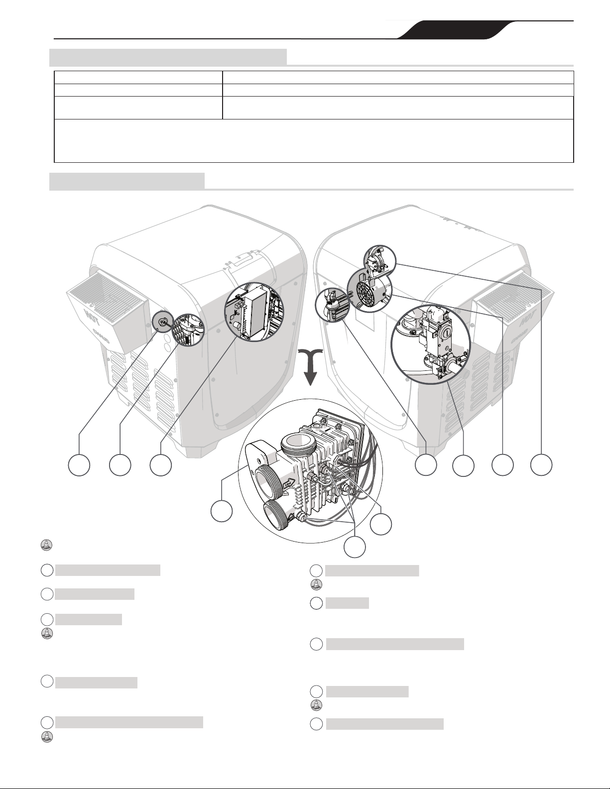
1.4 General Operation Description
The blower draws air and fuel through specially designed
orices, delivering a precise mixture to the burner,
located inside the sealed combustion chamber. Water
ows through the heat exchanger, which surrounds the
burner transferring the heat to the water. Exhaust gases
are then directed through a duct where it is vented to the
atmosphere.