497206DECEMBER 2, 2003 (Round Pool - 1" Rims)
DETERMINE POOL LOCATION
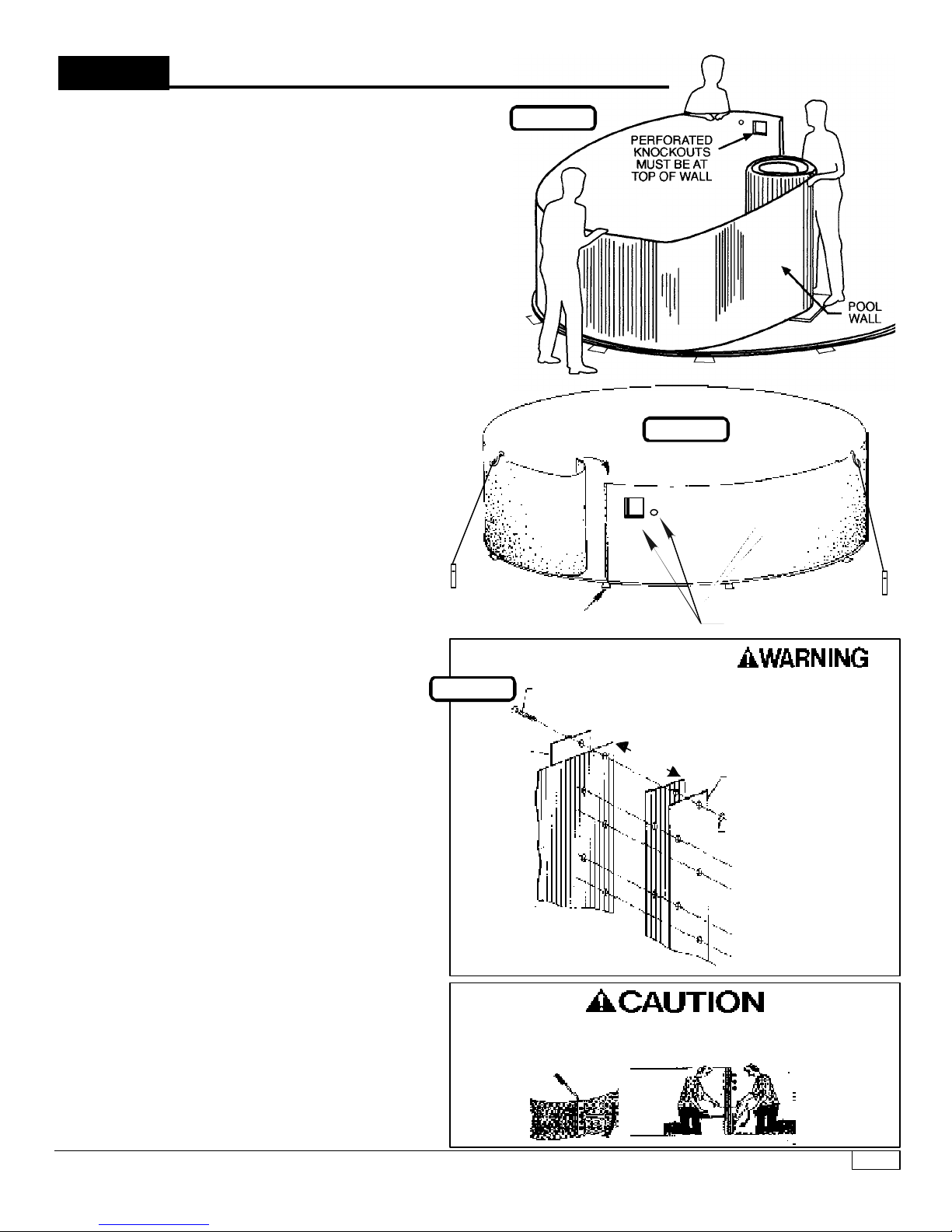
NO
NO
NO
YES
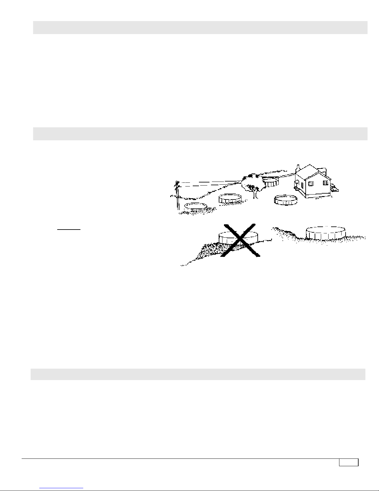
ALWAYS DIG AWAY TO
LEVEL THE SURFACE
DO NOT INSTALL POOL
BELOW GROUND LEVEL
1. READ INSTRUCTIONS
Takeyourtimeandreadtheseinstructionsthoroughlybefore youbeginthepoolinstallation. Followallinstructions.
Do not take short cuts. Refer to the back page of this Owner’s Manual and record the appropriate information.
2. CHECK LOCAL CODES GET BUILDING PERMITS IF NECESSARY
Check your local building and electrical codes concerning installation and location of above ground pools and/or
barrier devices. You should have all required permits before you start the ground preparation.
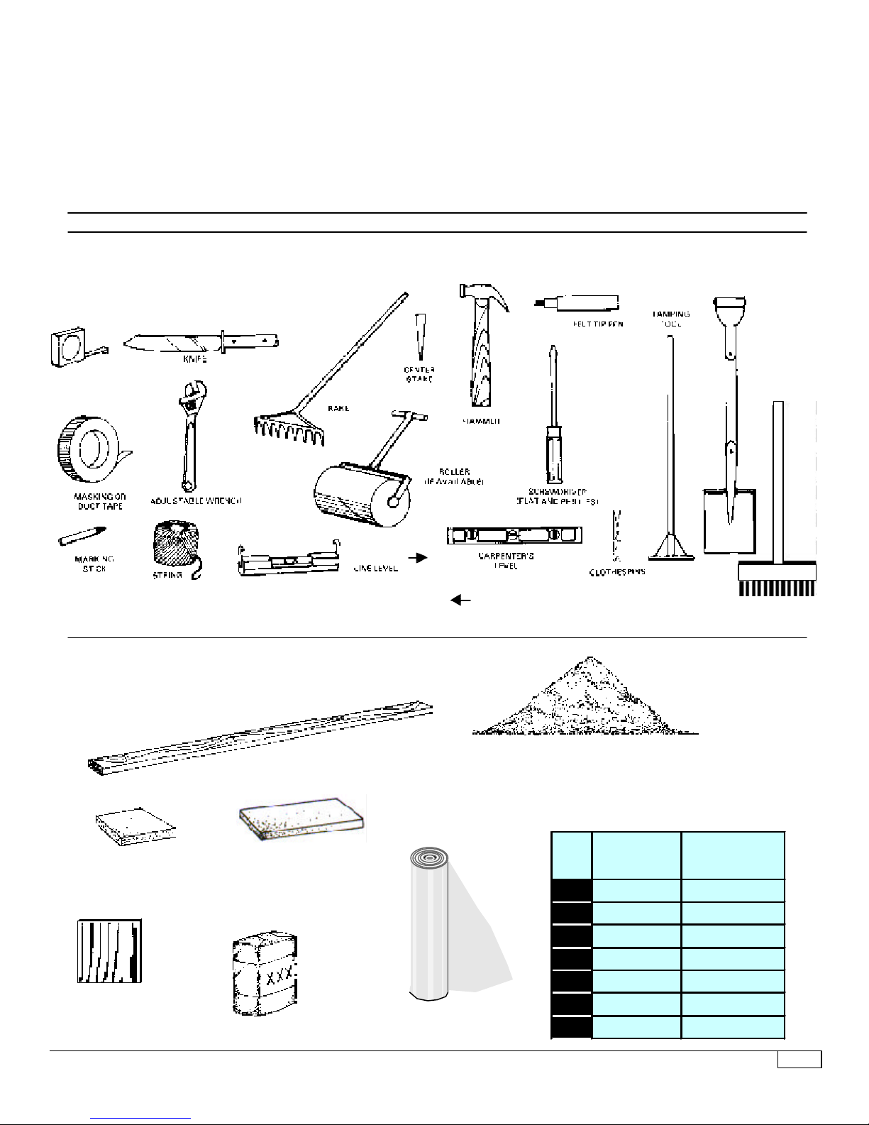
3. GET EVERYTHING TOGETHER
Review the tools and materials that you will need to install the pool. Purchase what you will need.
4. SETTING UP THE POOL
Do not attempt to install your pool on a windy day. The pool wall is extremely hard to handle in the wind and could
possibly collapse causing permanent damage to your wall. Install your liner on a warm, sunny day (65° F) so the
liner can stretch to fit the pool correctly.
IMPORTANT - BEFORE YOU START
Look over the various pool location situations shown at right.
1. TERRAIN
Look over your property for the most
ideal pool location. A large area is best.
If you have no flat area large enough for
the pool then try to pick a spot where
you would have the least amount of
digging to do. Do not install your pool
with any of the wall area underground -
or located in a major water drainage
depression or sewer drain field. Ground
area around the pool foundation should
be level for three feet out from base of
pool. DO NOT BACKFILL AGAINST THE
POOL WALL AND RIMS. THIS WILL
CAUSE DAMAGE TO THE WALL AND
RIMS AND VOID YOUR WARRANTY.
Remember there MUST be a flat,
three (3) foot area (minimum) around
the base of your pool wall to prevent
child drownings.
2. CONVENIENT ELECTRICAL OUTLETS
Your filter and other accessories are
operated by electricity. If there are no
outside electrical outlets, you must have
them installed by a qualified electrician in
accordance with the National Electrical
Code, Section 680.
3. OVERHEAD ELECTRICAL WlRES
The pool should never be placed directly
under any overhead power lines for
precautionary measures. In some
communities this is against the law.
4. UNDERGROUND CABLES AND
UTILITIES
Before you start digging into the
ground to level the surface, it
wouldbewise to check with your
telephone, electric and gas utili-
ties as to the location of any
underground lines or pipes.
5. TREES
Trees and their occupants are
not the best of friends with
swimmingpools.Fallingleaves,
branches and sap can be a
constant problem in keeping
thepoolwaterclean(alongwith
bird droppings and insects fall-
ing into the pool). These mate-
rials will necessitate cleaning
your filtering unit more often.
The further away from a tree,
the better for your pool.
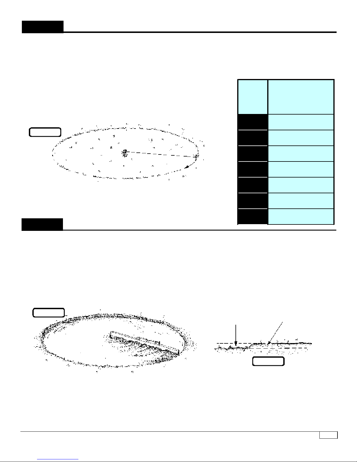
Itisimportantthatyourpoolsit on
firm, solid soil. The area must be
free of grass, stones, roots and
sharpobjects.Anystonesorroots
flush or just below the ground
surface must be removed. The
earth below the pool will com-
press under the weight of the wa-
ter and will expose these items to
the liner causing damage. Any
grass under the pool will rot and give
off an unpleasant odor. Avoid install-
ing your pool on ground that has been
recently treated with oil base weed
killers,chemicalsorhasbeenheavily
fertilized. Avoid areas growing Nut
Grass or Bermuda Grass (these
grasses can grow up through pool
liner).
DO NOT INSTALL YOUR POOL ON:
• concrete • asphalt • peat moss
• tar paper • sand • gravel • wood
• chemically treated soil • grass
• astroturf
Installing your pool on these surfaces
places undue stress on the sidewalls.
This can lead to wall/liner failure and
void your warranty.
GROUND SURFACE
DO NOT BUILD UP
SURFACE OR LOW SPOTS