Zodiac Tradewinds User manual

INTRODUCTION AND SWIMMING POOL SAFETY
Swimming pools are fun and we want you to enjoy your new pool for years to come. Please spend some
time reading your Owner’s Manual and Safety Packet (packaged with your pool) to understand the
operation and safety considerations of this product.
Serious permanent injury or death can occur in and around swimming pools. To prevent these tragic
accidents, please read, understand, and strictly enforce all safety rules.
You must post and maintain your safety sign and decals as instructed. If your sign or decals are missing
or damaged, please write for free replacements to:
Zodiac American Pools, Inc.
265 Industrial Blvd.
Midway, GA 31320
(800) 338-1013
Congratulations upon becoming a proud new pool
owner!Wetakeprideinbringingyouaqualityproduct
which will afford years of pleasure. Your pool is an
investment which deserves your care and attention.
This pool is designed for residential use only. Do not
use for commercial applications.
CAUTION:
Read all instructions
carefully before starting
theinstallation. Checkfor
missingpartsbyreviewing
theRepairPartsListinthe
back of this book.
© 2004 ZODIAC AMERICAN POOLS, INC.
ALL RIGHTS RESERVED • MADE IN U.S.A..
97042 English
Oval Flat Pool 1” Rims
Owner’s Manual
DECEMBER 2, 2003

297042DECEMBER 2, 2003 (TRADWDINDS - Oval Flat Pool 1” Rims)
SAFETY INSTRUCTIONS
As the owner, you have the most important role in reminding users of pool safety. You must set a safety example for
your family and guests. Use common sense around your pool and demand that others use common sense.
FAILURE TO HEED THESE WARNINGS CAN RESULT IN PERMANENT INJURY,
PARALYSIS FROM A BROKEN NECK, ELECTROCUTION OR DROWNING.
WATCH CHILDREN PREVENT DROWNINGS
•Always watchandsupervisechildrenplaying in oraroundpoolto prevent drowningorinjury.Never allow childrenoradults
to climb on the outside structure of the above ground pool. Do not place filters, pumps, tables, chairs or other objects
near the pool. Children may use these to enter the pool and drown. Position your filtration system a safe distance from
the pool to prevent young children from using the filter as a means of access to the pool.
NO DIVING
• Never dive, flip or jump into this above ground swimming pool. It is too shallow for safe diving. Ladders, decks, handrails
and top ledges (or anything else) are not to be used for diving. You can break your neck!
• Most serious permanent injuries, paralysis or deaths occur when dives are made from pool decks. Please read your four
page "Mandatory Reading" Booklet supplied with this pool before you purchase or fabricate a deck for your pool.
NO ALCOHOLIC BEVERAGES
• Never use your swimming pool if you have been drinking alcoholic beverages or taking medications or drugs. Shock,
unconsciousness, permanent injury or drowning could result.
FENCE SAFETY
• As an additional deterrent against child drownings, you should install around the pool an additional four (4) foot tall (above-
ground level) fence, wall or enclosure that is made of durable material. All gates and entries must be self-closing and self-
latching and equipped with hardware for permanent locking. All latches must be installed four (4) feet above the ground
surface and made inaccessible to toddlers from outside. If a building is part of the barrier, all doors, windows and patio
gates that could provide access to the pool must be self-closing and self-latching with permanent locks so that your pool
can not be entered by toddlers. Check all local and state building codes to insure your installation complies with all
requirements. Fences and barriers are not a substitute for adult supervision.
INSTALL POOL ABOVE GROUND
•Neverinstallyourabove-groundswimmingpoolbelowthegroundsurface.Thispoolmustbeinstalledonthegroundsurface
only. There should be a flat, three (3) foot area (minimum) around the base of your pool wall.
POOL COVER SAFETY
• If you use a winter cover and did not purchase it from us, the cover must meet CPSC Standard ES13. The cover must
have a tamperproof locking retainer cable that positions the cover around the pool wall and keeps it securely in place.
Never allow anyone, especially small children on the cover. Asphyxiation or drowning could result.
• We do not make a barrier cover. If you purchase a cover to act as part of a barrier system, it must meet ASTM Standard
F 1346. When purchasing any pool cover, please consult a swimming pool professional.
LADDER SAFETY
•Ladders must be located over an upright (for metal frame pools), on a solid base and kept level.
ELECTRICAL HAZARD
• Never touch or attempt to service electrical equipment, including your filter, when your body and/or the ground is wet.
Electrocution or permanent injury due to high voltage (120V AC) could result.
• To avoid electrocution hazard, never use an electrical power source for any electrical equipment or your filter unless it
is protected by a Class A (5 Milliampere Trip) Ground Fault Circuit Interrupter (GFCI) in accordance with the National
Electrical Code Section 680.
ELECTRICAL BONDING
•The pool should be bonded in accordance with Section 680-26 of the National Electrical Code. For further assistance contact
your dealer or a local licensed electrician.
KEEP WATER CLEAN
• Always keep your pool water clean so that the bottom is visible at all times. Individuals must be able to see that the water
is too shallow for diving, and must be able to see small children in the pool!
NO SWIMMING AFTER DARK
• Never use your swimming pool after dark or when you can not see the shallow depth of the water or the safety decals
or signs. If you ignore this, you have the sole responsibility for providing adequate lighting to the pool, safety signs,
walkways and decking. We recommend that you consult with a licensed electrical contractor or your power company to
provide adequate lighting. You must also comply with all national and local electric codes.
• Never cut holes in your pool wall to install lights or anything else unless the hole locations are factory installed. Failure
to obey this warning could cause structural damage to the pool wall, violently releasing large bodies of water. Wall
structural failures may cause serious injury, electrocution or property damage.

397042DECEMBER 2, 2003 (TRADWDINDS - Oval Flat Pool 1” Rims)
FAILURE TO HEED THESE WARNINGS CAN RESULT IN SERI-
OUS INJURY OR PROPERTY DAMAGE.
NO HORSEPLAY
• Never allow horseplay in or around the pool.
POOL CHEMICALS
• Do not place chlorine, chlorine tablets or sticks directly into the skimmer, or winterize your pool with liquid chlorine. Damage to
the skimmer, pool liner and filter will result. Failure to obey this instruction will void all component warranties.
• Always follow Chemical Manufacturer’s Instructions when storing, handling and dispensing pool chemicals.
• Your pool is exposed to more corrosive conditions than your car. Wax It often. At first sign remove rust and touch up immediately.
FILTER SAFETY
• If you use filters that are not manufactured by ZODIAC AMERICAN POOLS, INC. be sure that the filter is an Underwriters Listed
product for the USA (for other countries, it must be CSA, TUV/CE, or NOM approved) for your own protection against electrical
hazards. (See Filter Instructions for more information.)
CHECK FOR POOL DAMAGE AND WEAR
• Periodically check your pool and ladder components for damage and wear. Be sure all screws are in place. Replace all damaged
or worn components and tighten all screws before you use the pool, deck or ladders.
DO NOT MODIFY POOL
• Never modify the pool or accessories, or remove or drill holes in the pool, deck or ladder components unless instructed.
SHARP EDGES
• Your pool wall is made of thin metal. There is an inherent cut hazard with metal so use gloves during installation. Check all pool
and filtration parts for unusual sharpness. If you find unusual sharpness, please take steps to remove it with sand paper or file,
or return part for replacement.
REPLACEMENT PARTS
• Always use Original Equipment Manufactured (OEM) parts for you replacement requirements.
KEEP OFF TOP LEDGES
• Do not stand, sit, climb or step on top ledge of pool wall. These prohibited activities may cause injury or break the pool wall..
REMEMBER: HAVE FUN BUT BE SAFE
FOLLOW SAFETY INSTRUCTIONS
• Read and follow all Safety Instructions packaged with the pool, ladder, filter or any other accessory. Additional pool safety
publications, such as “Children Aren’t Waterproof” and “Pool And Spa Emergency Procedures For Infants”, can be obtained by
writing the National Spa and Pool Institute, 2111 Eisenhower Avenue, Alexandria, Virginia 22314.
POST WARNING SIGNS
• Make sure your "Warning" decals are in plain sight around your above-ground pool. Insist that all users, especially children and
young adults understand and obey safety messages.
CALL US FOR REPLACEMENT SAFETY MATERIALS
• If your “Warning” safety decals, signs or literature are missing, damaged or not legible, please write or call us for free replacements
at: Customer Service Department, 265 Industrial Boulevard, Midway, GA 31320, (800) 338-1013.
POOL EMERGENCIES
• Always have a strong light pole not less than 16 feet (4.88m) long with a blunt or hook end available at pool side in case of
emergencies.
• Always have near your telephone the number of the nearest Trauma or Rescue Unit.
These Safety Instructions require pool users to exercise common sense. Always use common sense in your use of this
product in order to avoid risks associated with electricity and water which can result in paralysis from diving, drowning
or electrocution.
CHILD DROWNING ALERT
U.S.ConsumerProductSafetyCommissionreportsthatdrowningsandneardrowningsofchildren,youngadults
and adults account for a substantial percentage of the risk of using this pool product. Children under the age of
5 years old are the highest risk. Please watch all children!
SAVE THESE INSTRUCTIONS!

497042DECEMBER 2, 2003 (TRADWDINDS - Oval Flat Pool 1” Rims)
1. READ INSTRUCTIONS
Take your time and read these instructions thoroughly before you begin the pool installation. Follow all instructions.
Do not take short cuts. This pool is designed for residential use only. Do not use for commercial applications.
2. CHECK LOCAL CODES—GET BUILDING PERMITS IF NECESSARY
Checkyourlocalbuildingandelectricalcodesconcerninginstallationandlocationofabovegroundpoolsand/orbarrier
devices. You should have all required permits before you start the ground preparation.
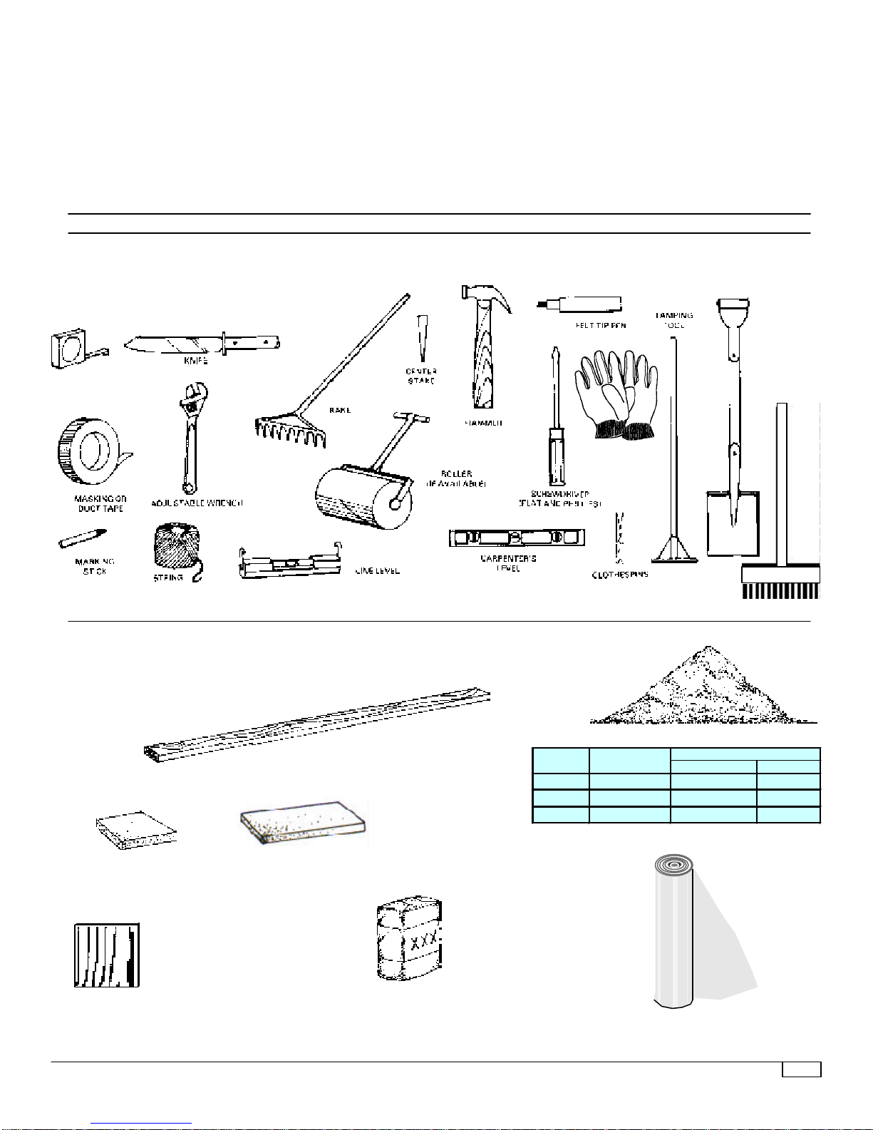
3. GET EVERYTHING TOGETHER
Review the tools and materials that you will need to install the pool. Purchase what you will need.
4. SETTING UP THE POOL
Donotattempttoinstallyourpoolonawindyday.Thepoolwallisextremelyhardtohandleinthewindandcouldpossibly
collapsecausingpermanentdamagetoyourwall.Installyourlineronawarm,sunnyday(65°F)sothelinercanstretch
to fit the pool correctly.
IMPORTANT - BEFORE YOU START
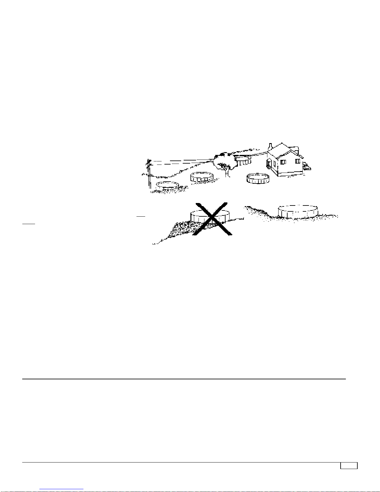
Look over the various pool location situa-
tions shown at right.
1. TERRAIN
Look over your property for the most ideal pool
location. A large area is best. If you have no flat
area large enough for the pool then try to pick a
spot where you would have the least amount of
digging to do. Do not install your pool with any of
thewall areaunderground-orlocatedinamajor
water drainage depression or sewer drain field.
Ground area around the pool foundation should
be level for three feet out from base of pool. .DO
NOT BACKFILL AGAINST THE POOL WALL
ANDRIMS. THIS WILL CAUSE DAMAGE TO
THE WALL AND RIMS AND VOID YOUR
WARRANTY. Remember there MUST be a
flat, three(3) foot area (minimum) around
the base of your pool wall to prevent
child drownings.
2. CONVENIENT ELECTRICAL OUTLETS
Yourfilterandother accessories are operatedby
electricity.Iftherearenooutsideelectricaloutlets,
youmusthavetheminstalledbyaqualifiedelec-
trician in accordance with the National Electrical
Code, Section 680fortheUSA(forothercountries,
check with the applicable electrical codes for your
area).
3. OVERHEAD ELECTRICAL WlRES
The pool should never be placeddirectly under
any overhead power lines for precautionary
measures.Insomecommunitiesthisisagainst
the law.
4. UNDERGROUND CABLES AND UTILITIES
Before you start digging into the ground to level the surface, it would be wise to
check with your telephone, electric and gas utilities as to the location of any
underground lines or pipes.
5. TREES
Trees and their occupants are not best of friends with swimming pools. Falling
leaves,branches and sap can be a constant problem inkeeping the poolwater
clean (along with bird droppings and insects falling into the pool). These
materialswillnecessitatecleaningyourfilteringunitmoreoften.Thefurtheraway
from a tree, the better for your pool.
NO
NO
NO
YES
ALWAYS DIG AWAY TO
LEVEL THE SURFACE
DO NOT INSTALL POOL
BELOW GROUND LEVEL
DO NOT BUILD UP
SURFACE OR LOW SPOTS
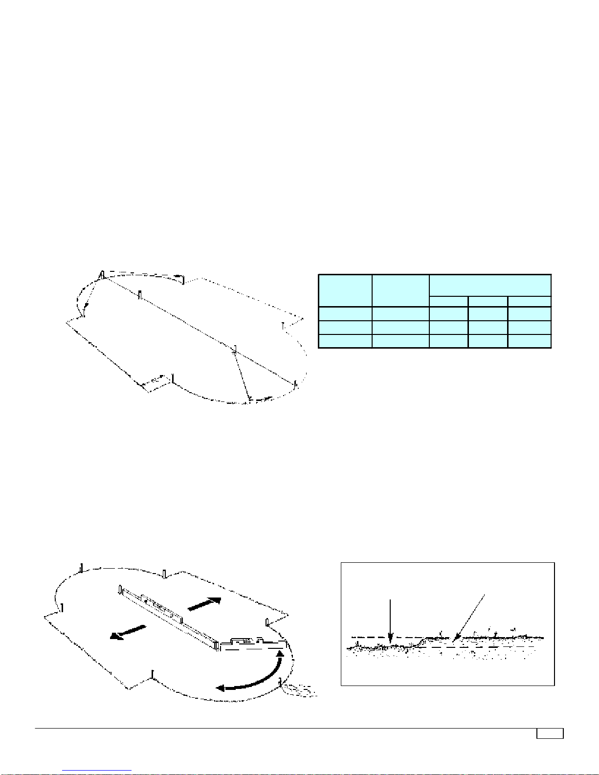
It is important that your pool sit on
firm,solidsoil.Theareamustbefree
of grass, stones, roots and sharp
objects. Any stones or roots flush or
just below the ground surface must
beremoved.Theearthbelowthepool
willcompressundertheweightofthe
water and will expose these items to
the liner causing damage. Any grass
under the pool will rot and give off an
unpleasant odor.
Avoidinstallingyourpoolongroundthat
has been recently treated with oil base
weed killers, chemicals or has been
heavily fertilized. Avoid areas growing
Nut Grass or Bermuda Grass (these
grassescangrowupthroughpoolliner).
DDO NOT INSTALL YOUR POOL ON:
• concrete •asphalt •peat moss
• tar paper • sand • gravel • wood
• chemically treated soil • grass
• astroturf
Installing your pool on these surfaces
places undue stress on the sidewalls.
Thiscanleadtowall/linerfailureandvoid
your warranty.
GROUND SURFACE
DETERMINE POOL LOCATION

597042DECEMBER 2, 2003 (TRADWDINDS - Oval Flat Pool 1” Rims)
Thinkofyourabovegroundpoolasabigdam.Ifthepool
is out of level or if the wall is worn or damaged, the
unevenpressure cancausethe walltobreak ortipand
allow thousands of gallons of rushing water to cause
extensive property damage and injury to anyone in its
path.
The amount of effort and care you put into the preparation
of your pool foundation and maintenance of the pool wall
can make a big difference in the life of your pool and liner.
Asolid, well-compacted, levelearthfoundationis the best
baseforyourpool.Takethetimetodoagoodandthorough
job as explained in these instructions.
MATERIALSYOU'LL NEED
IMPORTANCE OF LEVEL POOL FOUNDATION
STRAIGHT PLANK
(FOR LEVELING)
WASHED MASONRY SAND (SEE CHART)
CONCRETE BLOCKS
2" x 8" x 16"
(SEE CHART)
TOOLS YOU'LL NEED SHOVEL
TAPE MEASURE PUSH BROOM
MEDIUM BRISTLE
NOTE: Do not install your pool frame on a sand base! Use sand ONLY on
theinsideofthepooltoformthecoveandtoprovideasmoothbase
for the liner.
2' x 2' BOARD
(ANY TYPE)
CONCRETE BLOCKS
2" x 8" x 8"
(SEE CHART)
CHALK OR FLOUR
(FOR MARKING GROUND)
GLOVES
(2"x8"x8") (2"x8"x16")
1224 3 TON 20 10
1530 5 TON 22 12
1833 6 TON 24 12
CONCRETE BLOCKS REQUIREDSAND REQUIRED
FOR BOTTOM
POOL
SIZE
VINYL OR
PLASTIC

697042DECEMBER 2, 2003 (TRADWDINDS - Oval Flat Pool 1” Rims)
NOTES

797042DECEMBER 2, 2003 (TRADWDINDS - Oval Flat Pool 1” Rims)
A
A
C
B
C
B
C
CFIG. 1
FIG. 3
DO NOT FILL IN
THISAREA
DIGEARTHAWAYTO
MAKELEVEL
1. MARK OFF POOL AREA AND REMOVE SOD
Using the chart below and Figure 1, mark off pool area as shown. Measure carefully and drive pegs into the ground
where indicated.
a. Insert “A” pegs as shown (A to A) and connect with a string.
b. Measure (A to B) and insert “B” pegs.
c. Tie a loop at one end of a string and drop it around a “B” peg. Stretch the string out to the closest “A” peg and attach
amarking stick. Mark off a semi-circle on both ends of the pool as shown,using flour, spray paint orsomething similar
which is easily visible.
d. From “A” pegs, measure (A to C) and insert “C” pegs.
e. From each “C” peg, measure 2' and scribe a straight line as shown (Figure 1).
f. Removeallsod, sticks,stones,androots withinthemarked pool area.Carefullyremove and replace“A”and “B”pegs
when digging.
BE SURE:
• Recheck the level of entire pool area. The success of installation depends upon how well this is performed.
FIG. 2
2. LEVEL POOL AREA
Unless you have access to a surveyor’s level, the best, most accurate way to level the ground is with a straight plank
(2 x 4 will do but it should be straight) and a carpenter’s level (Figure 2). Find the lowest spot within the pool area and
level the ground to the lowest point. Dig away the high areas — do not fill in low areas (Figure 3).
REMEMBER: You must also provide a three foot level area outward from the pool frame so the pool wall will serve
as a barrier to toddlers.
A TO A A TO B A TO C
1224 18' x 26' 26' 7' 9'-10"
1530 21'-6" x 32' 32' 8'6" 12'
1833 24'-6" x 35' 35' 10' 14'-2"
AREA
NEEDED
FOR POOL
POOL
SIZE
MEASUREMENTS
PEG TO PEG

897042DECEMBER 2, 2003 (TRADWDINDS - Oval Flat Pool 1” Rims)

997042DECEMBER 2, 2003 (TRADWDINDS - Oval Flat Pool 1” Rims)
3. ASSEMBLE SUBSTRUCTURE
a. Attach two “U” brackets to each bottom strap with 5/16-18 x 1/2" machine screws and hex nuts as shown in Figures 4 and
5. Insert brackets and screws from under side of straps.
b. 12' and 18' OVALS
ConnectbottomstrapsandjoinerstoformstrapassembliesasshowninFigure8.Overlaptwoendholesineachjoinerand
fasten with two 5/16-18 x 1/2" machine screws and hex nuts (Figure 6). See chart (col. A) for number of joiners required in
each strap assembly.
15' OVALS
Lay out and connect straps and joiners as shown in Figures 7 and 8. Overlap four holes in joiners so arrows point to each
other (Figure 8). Fasten at each connection with two 5/16-18 x 1/2" machine screws and hex nuts (Figures 6 and 7).
c. Lay strap assemblies in pool area (Figure 8). Carefully space each assembly according to the measurement given in the
chart (col. C). (Measurements are between straps).
d. ChecklengthofstrapassembliesacrossthepoolasshowninFigure9andchart(col.D).Dimensionsmustagreewiththose
in chart.
e. Check “squareness” of strap assemblies by measuring diagonally from corner to corner as shown in Figure 9. Diagonal
measurements must be the same; assemblies must be level in all directions.
f. Insert concrete blocks at each bottom strap as shown. Large block extends 4" beyond end of strap (Figure 11); small block
is centered under bracket towards inside of pool (Figure 12).
IMPORTANT: Concrete blocks must be flush with ground level and level with each other in all directions.
9. Set spacer plates between bottom straps as shown in Figure 8. Fasten at large hole with a 5/16-18 x 1/2" machine screw
andhexnut(insert screws from under sideofstrap,leavenut loose - Figure 10).Alignsmallholesand fasten from topwith
a #10 x 1/2” screw (Figure 10) and then tighten the 5/16-18 hex nut.
NOTE: Spacer plates overlap at each bottom strap as shown (Figure 8).
h. Before proceeding, re-check squareness of substructure as described in e.
BE SURE:
¨Check level before proceeding . . . entire substructure must be level in all directions.
¨Recheck squareness.
COLUMN A COLUMN B COLUMN C COLUMN D
NUMBER OF
JOINERS IN
EACH
ASSEMBLY
NUMBER OF
ASSEMBLIES
DISTANCE
BETWEEN
BOTTOM
STRAP
DISTANCE FROM
END OF BOTTOM
STRAP TO END
OF BOTTOM
STRAP
1224 2 5 32-1/4" 17'-2-3/8"
1530 4 6 27-1/8" 20'-8"
1833 4 6 27-1/8" 23'-7-1/2"
POOL
SIZE

10 97042DECEMBER 2, 2003 (TRADWDINDS - Oval Flat Pool 1” Rims)
TABS FASTEN TO
SIDES OF UPRIGHT.
TIGHTEN EQUALLY
NOTE: Tabs will flex
to fit upright.
Top plate will have a
1/4” gap away from
center upright.

11 97042DECEMBER 2, 2003 (TRADWDINDS - Oval Flat Pool 1” Rims)
4. ASSEMBLE CENTER UPRIGHTS
a. Fastentopplatetosides of upright with two#10x1/2”screws(Figure14).Fastenthetopplatetothefrontoftheuprightwith one#10
x 3/4" sheet metal screw (Figure 14) NOTE: Front tab will have 1/4” gap in front of center upright.
b. Follow a. for each center upright.
BE SURE:
¨Check level before proceeding. Entire substructure must be level in all directions.
¨Recheck squareness.
a. Position center upright over “U” bracket and fasten with a 1/4-20 x 1-3/4" machine screw and nut (Figure 18).
b. Insert tabs of angular brace into slots on center upright (Figure 17); set other end of angular brace over “U” bracket on bottom strap
(Figure 19).
c. Fasten angular brace to center upright with two #10 x 1/2” screws (Figure 17). Fasten bottom of angular brace with a 1/4-20 x 1-3/
4" machine screw and nut (Figure 19).
d. Repeat a., b. and c. on both sides of pool.
IMPORTANT: This is the side support structure of your pool, therefore, you must be sure that all screws and nuts are tightened.
DO NOT omit any screws and nuts!
e. Installacenterrim(seechartforlengthofrimtobeused)andconnectorbetweeneachcenterupright(Figure16).AsshowninFigure
15,fitnotchedareaofconnectoraroundcenterupright,insertrimendintoconnector,andslidedown.Followthisprocedure,alternating
connector and rim on both sides of pool.
5. ASSEMBLE SIDE SUPPORT STRUCTURE
POOL
SIZE LENTGH OF
CENTER RIM
1224 33"
1530 27-3/4"
1833 27-3/4"

12 97042DECEMBER 2, 2003 (TRADWDINDS - Oval Flat Pool 1” Rims)
6. ASSEMBLE CIRCULAR BOTTOM FRAMEWORK
a.FormasemicircleofrimsandfootplatesoneachendofthepoolasshowninFigure20. Snaprimsintofoot plates engaging
all tabs as shown in Figure 22. Where rims meet center uprights, insert ends into notch at base of upright (Figure 21).
b. Insert concrete blocks at each foot plate—blocks must be flush with ground surface and level in all directions (Figure23).
c. Check the level of your pool frame. It is not difficult to make adjustments now. Spending a few extra minutes now may
save you hours of unnecessary work later!
HINT: All sand should be placed inside the rims before installing the pool wall.

13 97042DECEMBER 2, 2003 (TRADWDINDS - Oval Flat Pool 1” Rims)
b. The skimmer knockouts begin approximately
12"fromthebeginningofthepoolwall.Begin
wallinstallationatthefootplate12"fromwhere
your filter will be located. As wall is uncoiled,
guidethebottomedgeintotherimgrooveuntil
wallends,overlapandtheholesalign.Ifends
overlap too much, gently nudge rims toward
outside of pool. If ends do not meet, gently
nudge rims toward inside of pool.
c. As you are joining the wall ends, attach the
reinforcingbarsontheoutersidesofthepool
wall using the 5/8" machine screws and hex
nuts as shown in Fig. 26 - insert screws from
insideofpool. NutsandwashersMUSTbeon
outside(FIG.26). Toeliminateburrsonscrew
heads,holdscrewsinplacewithascrewdriver
and then turn the nuts to tighten. Tighten the
nutstoa maximumtorqueof70 inchpounds.
Fileoffanyburrsonscrewheadsandcoverthe
inside wall joint with heavy tape.
BE SURE:
¨Tighten all nuts - do not omit any screws in
wall joint.
¨Check the entire substructure for sharp
edges or corners. These areas must be
covered with heavy cloth or duct tape.
¨Pool must be level. Check pool level at
several locations as shown in FIG. 28. If
level varies 1" or more dismantle the pool
wall and re-level the entire bottom frame-
work.
7. INSTALL POOL WALL
a. Setcoiledpoolwallona2X2woodboardinsidethepoolarea
(FIG. 24). The perforated knockouts in the wall are for an
optionalthru-the-wallskimmer.Whetheraskimmerisusedor
not,theseknockoutsMUSTbepositionedattheTOPofthepool
(FIG. 24 & 25).
IMPORTANT:
If you are using a thru-the-wall skimmer, refer to your
Skimmer Owner’s Manual and remove the knockout now.
Ifyouarenotusingathru-the-wallskimmerdonotremove
the knockout panel. Cover ALL perforations (inside the
pool) with heavy cloth or duct tape.
POOL WALL MUST BE INSTALLED WITH ONE REINFORCING BAR ON
THE INSIDE AND ONE ON THE OUTSIDE. FAILURE TO INSTALL BOTH
BARS AS SHOWN WILL CAUSE COLLAPSE OF POOL!
WASHER

14 97042DECEMBER 2, 2003 (TRADWDINDS - Oval Flat Pool 1” Rims)
Follow these steps before adding
sand to pool bottom or building cove.
Add
plastic or
vinyl
here
before
building
the cove
VINYL
OR
PLASTIC
TOP VIEW
Pool
Understructure
COVER THE WALL AND
POOL FLOOR AREA WITH
VINYL OR PLASTIC
(APPROXIMATELY 12” IN
WIDTH) BEFORE BUILDING
A COVE AROUND THE
POOL. THIS WILL HELP TO
PREVENT SAND LOSS AND
THE POOL LINER FROM
GOING UNDERNEATH THE
POOL RIMS WHICH MAY
DAMAGE THE LINER.
POOL WALL
Cover the pool
understructure and wall area
with vinyl or plastic as
shown here. Follow the
instructions on page 15 to
build a cove and add layer of
sand to pool bottom.
TOP VIEW
OF POOL
COVE OF SAND
COVER THE POOL UNDERSTRUCTURE WITH VINYL OR PLASTIC. THIS WILL
HELP PREVENT SAND DISPLACEMENT WHICH MAY EXPOSE THE LINER TO THE
UNDERSTRUCTURE OF THE POOL AND DAMAGE THE LINER.
1.
2.

15 97042DECEMBER 2, 2003 (TRADWDINDS - Oval Flat Pool 1” Rims)
8. BUILD A COVE AROUND INSIDE BASE OF POOL
a. Buildan8"coveoffirmlypackedmasonrysandaroundtheinsidebaseofthepoolframe(FIG.28).USEDAMPENEDSAND
ONLY! DO NOT USE PEAT MOSS OR ANY TYPE OF “POOL BASE” MATERIAL. The cove is absolutely necessary as it
prevents the liner from creeping underneath the wall and rupturing.
NOTE: Commercially manufactured pool coving may be substituted for sand providing it does not contain ionomer
foams (These materials are not compatible with PVC). Should you have any questions please consult your
pool dealer or the pool cove manufacturer for the material composition of the coving.
b. Spread a 1" - 2" layer of sand over the entire pool area and tamp down (FIG. 28).
c. Periodically check the base of your pool to be sure the cove is firmly packed.
IMPORTANT: Certain types of commercial substances referred to as “Pool Base” can cause damage to your pool
liner. This manufacturer will not be responsible for damage resulting from the use of such materials.
BE SURE:
¨The cove is a vital structural element of your pool. DO NOT OMIT!
¨Check pool level before installing the liner.
FIG. 28
FIG. 29
1"-2" LAYER OFSAND
8"COVEOFSAND
LINELEVEL

16 97042DECEMBER 2, 2003 (TRADWDINDS - Oval Flat Pool 1” Rims)
9. INSTALL LINER
Choose a warm, sunny day (at least 65°F) to install your liner. The liner is manufactured from a high grade flexible
vinyl material. This material is designed to stretch into shape during installation; therefore, it must be warm enough
to allow for the proper amount of stretch when installed in the pool. To insure a wrinkle-free form fit, Install your liner
on a warm sunny day when the temperature is at least 65°F.
a. Carefully open the liner carton. Do not use a knife or sharp instrument to open the box. As you install the liner, inspect
surface for possible punctures.
b. TherearetwoNODIVINGwarningdecalspackagedinsideyourlinercarton.Setthemasideinasafeplaceuntilyourpool
has been filled with water. See STEP 14 for installation of NO DIVING decals.
c. Youshouldhavethehelpofatleastfourpeople.Unfoldthelinersoitresemblesarollofcarpet.Lift theliner overthepool
and begin unfolding. Seam side of liner should face the ground.
d. Keeplineraway fromthecovearea ofthepool.As youunfoldtheliner, locatethesideseam andpositionitparallel tothe
corrugations in the pool wall (FIG. 30). All other seams should form straight lines across the pool. Be sure seam is away
fromskimmerknockouts.Pulllinersidesoverthetopofthepoolwallanddowntheoutside.Holdinplacewithspring-type
clothespins.
e. Adjusttheoverhangofthelinersoitmeasuresthesameallthewayaroundthepool.Allowabouteightfeetoflinertotouch
the ground in the center of the pool area (FIG. 31).
f. Start adding water; gently pull liner bottom toward side walls as the weight of the water pushes the liner into place.
KEEP LINER AWAY
FROMCOVEAREA
FIG. 31
PULL SIDES OF LINER DOWN THE
OUTSIDE OF POOL WALL
SIDE SEAMS PARALLEL TO
CENTER UPRIGHTS
FIG. 30
OVERHANGMUST
BEEQUALALL
AROUNDTHE
POOL'SCURVED
END
BE SURE:
Before installing liner, cover the top plates with tape. Remove tape after liner has been installed. Liner is heavy - do
not attempt to install it yourself.
¨Pull liner gently - avoid sharp tugs.
¨Do not cut or trim edges of liner.
¨All seams must be straight.
¨The bottom round seam should be positioned evenly around the inside circumference of the pool.
¨Adjust overhang evenly allowing minimum tension on pool wall .
ALLOW ABOUT 8 FEET
OF LINER TO TOUCH
THE GROUND
OVERHANGMUST
BEEQUALALL
AROUNDTHE
POOL'SCURVED
END

17 97042DECEMBER 2, 2003 (TRADWDINDS - Oval Flat Pool 1” Rims)
NOTES

18 97042DECEMBER 2, 2003 (TRADWDINDS - Oval Flat Pool 1” Rims)
10. ATTACH LINER TO POOL
a. Aspoolfills,watchfortensionandwrinklesintheliner.Releasetheclothespinsperiodicallytorelievetensionandremove
wrinkles.
b. Continuefillingpoolto16"depthandstop.Removeafewclothespinsatatimeandrelease tensionin linersidematerial.
Replace the clothespins.
c. Snap the flexible ribbed coping over the liner (FIG. 32). Work around the entire pool a few feet at a time.
d. Install metal stabilizers over the coping as shown in FIG. 33. Gently tap each stabilizer into place with a rubber mallet or
a block of wood.
e. Center the short stabilizers between uprights on the straight side of the pool (Figure 33). Install the long stabilizeraround
the curved ends of the pool (Figure 33). Overlap stabilizers along the curved end given in chart. (Figure 32).
BE SURE:
¨Carefully measure the distance between the water level and top edge of the pool wall (at several points). These
measurementsshouldnotvarymorethanoneinch.Iftheyvarymorethan1",yourwarrantywillbevoidandthemanufacturer
will not assume responsibility for any personal injury or pool damage.
11. FILL THE POOL
Continue to fill with water as you assemble the remaining parts of your pool. If you have purchased a thru-the-wall
skimmer, stop filling pool when water level is 20"-22" from the top; refer to instructions packed with skimmer for
assembly of thru-the-wall skimmer.
FIG. 32
FIG. 33
SHORT
STABILIZERS
POOL
SIZE APPROXIMATE DISTANCE
TO OVERLAP STABILIZERS
1224 7"
1530 3"
1833 4"
APPROX.
OVERLAP
WALL
STABILIZER
RIBBEDCOPING
VINYLLINER
WALL

19 97042DECEMBER 2, 2003 (TRADWDINDS - Oval Flat Pool 1” Rims)
NOTES

20 97042DECEMBER 2, 2003 (TRADWDINDS - Oval Flat Pool 1” Rims)
12. ASSEMBLE UPRIGHTS (CURVED ENDS)
a. Fasten uprights to foot plates with three #10 x 1/2” screws. (FIG. 35)
b. IfyouhavethetopplateandfootplateshowninFIG.35:Hookthebackflangeofthetopplateoverthestabilizerthenfasten
top plate to upright with three #10 x 1/2” screws. Fasten sides first (FIG. 34).
c. Using a carpenter's level, make sure the uprights are plumb.
FIG. 35
#10 X 1/2” SCREW
TOPPLATE
SLOT FOR
LEDGECOVER
HOOKBACK
FLANGEOVER
1/2" rim
UPRIGHT
FOOTPLATE
Table of contents
Other Zodiac Swimming Pool manuals