Zoeller 350 User manual

© Copyright 2014 Zoeller Co. All rights reserved.
© Copyright 2010. All rights reserved.
1
ATTENTION: READ CAREFULLY BEFORE ATTEMPTING TO INSTALL OR OPERATE YOUR PUMP. PROTECT YOURSELF AND OTHERS BY OBSERVING ALL
SAFETY INFORMATION AND ADDITIONAL INSTRUCTIONS INCLUDED WITH EQUIPMENT. FAILURE TO COMPLY WITH INSTRUCTIONS COULD RESULT IN
PERSONAL INJURY AND/OR PROPERTY DAMAGE! RETAIN FOR FUTURE REFERENCE.
SECTION: 6.10.145
FM2339
0810
Supersedes
0509
INSTALLATION INSTRUCTIONS
These installation instructions are applicable for Models 350 & 351 Pressure Booster Pumps Only
PREINSTALLATION CHECKLIST - ALL INSTALLATIONS
Pressure Booster System Models 350 & 351
SEE BELOW FOR LIST OF WARNINGS
-celedednuorgylreporpaotnideggulpsipmupehttahterusekaM.1
trical receptacle.Use an Underwriters Laboratory listed circuit ana-
lyzer to test for proper installation of the circuit and ground. Any service
to circuits or receptacles should be conducted by a qualified licensed
electrician.
.2 All electrical installations must conform to the requirements of the National Electri-
cal Code and all local codes.
.3 It is strongly recommended that the unit be plugged into a GFCI protected cir-
cuit.
ehtgniggulpnuybrotomropmupehtgnicivreserofebrewoptcennocsiD.4
unit from the outlet.
.5 Do not touch the motor when operating and allow the motor to cool
before touching.
6 -nocretaweldnahotdengisedtonsiti;ylnoretawraelceldnahottli
ubsipmuP.
taining sand, silt or other abrasives.
7. Do not use to pump flammable or explosive fluids such as gasoline,
fuel oil, kerosene, etc. Do not use in flammable and/or explosive
atmospheres.
8. Do not use this product in hazardous environments or anywhere a
spark could potentially ignite explosive gases.
9. tewanororetawnignidnatselihwrosdnahtewhtiwtcudorpsihteldnahtonoD
or damp surface.
10.Units are supplied with an automatically resetting thermal overload device and
can restart without warning.
11. Provide a means of pressure relief if the pump discharge can be shut
off or obstructed. Pumps operating against a closed discharge can
create very hot pumped liquid, which can cause burns.
12.Do not install unit outdoors. This unit is not weatherproof nor is it able to be sub-
mersed in water or any other liquid.
13.Do not ground to a gas supply line.
14.Hazardous voltage. Can shock, burn or cause death. Ground pump
before connecting to power supply.
15..epipegrahcsidnievlavfeilererusserpllatsnI!erusserpsuodrazaH
Release all pressure on system before working on any component.
16.According to the state of California (Prop 65), this product contains chemicals known
to the state of California to cause cancer and birth defects or other reproductive
harm.
17.Risk of Electric Shock. This pump has not been investigated for use in swimming
pool areas.
18.Use only components that are rated for maximum pressure pump can produce when
used in boosting system or any other system. Do not exceed the total maximum
pressure boost as listed per model in Performance Chart A.
19.Never examine, make wiring changes or touch the motor before disconnecting the
main electrical supply switch. The thermal device may have opened the electrical
circuit. All motors should be equipped with a correctly fused disconnect switch to
provide protection. Consult local or United States National Electrical Codes for
proper fuse protection based on motor data chart (See Chart B).
1. Make certain that the power source conforms to the requirements of the equipment
as stated on the product nameplates and wire motor for correct voltage. See Chart
B of this manual, and motor nameplate.
2. Check hoses for weak or worn conditions before use and make certain that all
connections are secure.
3. Periodically inspect the pump for damage and perform routine
maintenance as required.
4. The maximum temperature of the pumped liquid must not exceed 120°F. The
minimum allowable temperature is 40°F.
5. Support pump and piping when assembling and when installed. Failure to do so
may cause piping to break, pump to fail, motor bearing failures, etc.
6. This unit is not waterproof and is not intended to be used in showers, saunas or
other potentially wet locations. The motor is designed to be used in a clean dry
location with access to an adequate supply of cooling air. Ambient temperature
around the motor should not exceed 149ºF (65ºC).
7. Supply voltage must be within ± 10% of nameplate voltage. Incorrect voltage can
cause fire or seriously damage motor and voids warranty. If in doubt, consult a
licensed electrician.
8. Use wire size specified in wiring Chart B. Make certain that the power supply con-
forms to the electrical specifications of the motor supplied. See Motor Data Chart
B. Connect pump to a separate branch circuit with no other appliances on it. If
motor wiring diagram differs from diagram shown below, follow diagram on motor.
REFER TO WARRANTY ON PAGE 2.
SEE BELOW FOR LIST OF CAUTIONS
NOTE: Pumps with the “CSA-CUS” mark are tested to UL standard UL778 and certified
to CSA standard C22.2 No. 108.
021726
®
Product information presented
of publication. Consult factory
regarding discrepancies or
inconsistencies.
MAIL TO: P.O. %2;/RXLVYLOOH.Y 40256-0347
SHIP TO:&DQH5XQ5RDG/RXLVYLOOH.Y 40211-1961
380PFAX (502) 774-3624
visit our web site:
www.zoeller.com
Your Peace of Mind is Our Top Priority
®
Changes to this document must be sent to F&W for production.
Original Indd document was corrupted. is is pulled from previous pdf document.
FM2339
0314
Supersedes
0810
021726

© Copyright 2014 Zoeller Co. All rights reserved.
© Copyright 2010. All rights reserved.
2
Manufacturer warrants, to the purchaser and subsequent owner during the warranty period,
everynewproducttobefreefromdefectsinmaterialandworkmanshipundernormaluseand
service, when properly used and maintained, for a period of one year from date of purchase
by the end user, or 18 months from date of original manufacture of the product, whichever
comes first. Parts that fail within the warranty period, one year from date of purchase by
the end user, or 18 months from the date of original manufacture of the product, whichever
comes first, that inspections determine to be defective in material or workmanship, will be
repaired, replaced or remanufactured at Manufacturer's option, provided however, that by
so doing we will not be obligated to replace an entire assembly, the entire mechanism or the
complete unit. No allowance will be made for shipping charges, damages, labor or other
charges that may occur due to product failure, repair or replacement.
This warranty does not apply to and there shall be no warranty for any material or product
that has been disassembled without prior approval of Manufacturer, subjected to misuse,
misapplication, neglect, alteration, accident or act of God; that has not been installed,
operated or maintained in accordance with Manufacturer's installation instructions; that
has been exposed to outside substances including but not limited to the following: sand,
gravel, cement, mud, tar, hydrocarbons, hydrocarbon derivatives (oil, gasoline, solvents,
etc.), or other abrasive or corrosive substances, wash towels or feminine sanitary products,
etc. in all pumping applications. The warranty set out in the paragraph above is in lieu of all
other warranties expressed or implied; and we do not authorize any representative or other
person to assume for us any other liability in connection with our products.
Contact Manufacturer at, 3649 Cane Run Road, Louisville, Kentucky 40211, Attention:
Customer Service Department to obtain any needed repair or replacement of part(s) or
additional information pertaining to our warranty.
MANUFACTURER EXPRESSLY DISCLAIMS LIABILITY FOR SPECIAL, CONSE-
QUENTIAL OR INCIDENTAL DAMAGES OR BREACH OF EXPRESSED OR IMPLIED
WARRANTY; AND ANY IMPLIED WARRANTY OF FITNESS FOR A PARTICULAR
PURPOSE AND OF MERCHANTABILITY SHALL BE LIMITED TO THE DURATION OF
THE EXPRESSED WARRANTY.
Some states do not allow limitations on the duration of an implied warranty, so the above
limitationmaynotapplytoyou. Some statesdonot allow theexclusionor limitation ofincidental
or consequential damages, so the above limitation or exclusion may not apply to you.
This warranty gives you specific legal rights and you may also have other rights which
vary from state to state.
LIMITED WARRANTY
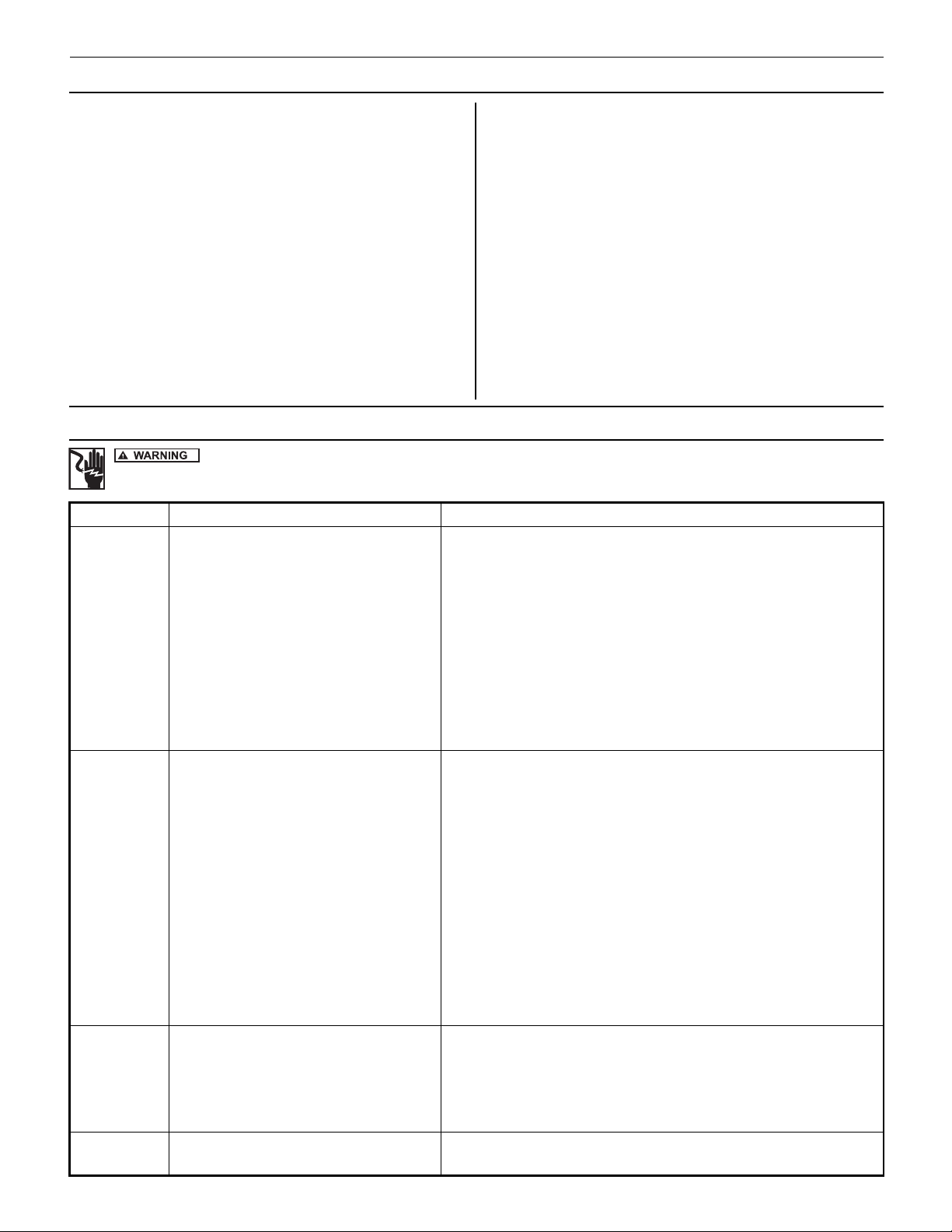
Symptom Possible Cause(s) Corrective Action
Pump won’t start or
run at full speed.
1. Blown fuse or open circuit breaker. 1. Replace fuse or close circuit breaker. See wire size chart for proper breaker/fuse size.
2. Power supply in OFF position. 2. Turn power on.
3. Incorrect voltage at motor (check voltage with motor
running).
3. Low voltage.
a. Voltage must be within ± 10% of motor rated voltage. Check incoming voltage.
Contact power company.
b. Make certain that voltage of motor matches voltage of power supply. See motor
name plate and motor wiring diagrams.
c. Check wire size from main switch to pump. See wire size chart for correct wire size.
4. Loose, broken or incorrect wiring. 4. Rewire any incorrect circuits. Tighten connections, replace defective wires.
5. Defective motor. 5. Replace motor.
6. Pump hydraulic components clogged/worn/damaged. 6. Replace worn parts or entire pump. Clean parts if required.
Pump operates,
but delivers little
or no water.
1. Manual or solenoid valves plumbed into system
restricting flow.
1. a. Check all valves on pump inlet and discharge sides of system to be sure they are
opened properly to allow flow to and from the pump.
b. Bleed trapped air in pump which keeps water from reaching the pump. (Normally
due to closed valve in discharge plumbing).
2. In-line filter restricting flow. 2. Check all in-line filters to be sure they are not plugged or restricted.
3. Low line voltage. 3. See low line voltage corrective action (above).
4. Inadequate water supply to booster pump. 4.
Check pressure on inlet side of booster to be sure positive pressure is maintained to the
booster pump.
5. Undersized piping. 5. Replace undersized piping.
6. Leak on inlet side of system. 6. Make sure connections are tight. Repair leaks as necessary.
7. Worn or defective pump parts or pump. 7. Replace worn parts or entire plugged impeller. Clean parts if required.
8. Suction lift too great. 8. Pump should be operated under flooded suction only.
9. Pump not primed. 9. Prime pump -
Make certain inlet pipe is drawn up tight and pump and pipe are full of water.
Excessive noise
while pumping.
1. Pump not secured to firm foundation. 1. Secure properly.
2. Piping not supported. 2. Make necessary adjustments.
3. Restricted inlet line. 3. Clean or correct.
4. Cavitation (noise like marbles in pump). 4. Increase inlet pipe size.
5. Worn motor bearings. 5. Replace bearings or motor.
Pump leaks. 1. Worn mechanical seal (leaks at shaft). 1. Replace shaft (rotary) seal.
2. Worn o-ring seals. 2. Replace o-ring seals, located inside both ends of the stainless steel shell.
ELECTRICAL PRECAUTIONS - Before servicing a pump, always shut off the main power breaker and then unplug the pump. Make sure you are not
standing in water and are wearing insulated protective sole shoes. Under ooded conditions, contact your local electric company or a qualified licensed electrician for discon-
necting electrical service prior to pump removal.
TROUBLE SHOOTING GUIDE

© Copyright 2014 Zoeller Co. All rights reserved.
© Copyright 2010. All rights reserved.
3
DESCRIPTION
SPECIFICATIONS
Component Description
Motor Rear access - Nema 56J face
Bearings Ball-ball, permanently lubricated
Impellers GFN2
Diffuser GTX 820
Pump shaft 316 Stainless steel
Pump shaft coupling 316 Stainless steel
Pump housing Powder-coated cast iron
O-Rings Viton
Seal composition Carbon-ceramic, stainless steel spring and Viton
Chart C: Material Construction
Chart B: 115V, 60 Hz Motor Data & Minimum Wire Size (Gauge)
†Thermal overload protector - automatic reset.
Motor HP Service Factor
Motor Amps Phase†
Distance In Feet From Motor To Service Panel
Breaker Size
(Amps)
0-50 50-100 100-150 150-200 200-300
Wire Size
1/2 8.6 1 14 14 14 12 12 15
3/4 13.0 1 12 12 12 12 10 20
Pressure booster pumps increase water pressure from city mains
or private water systems. This system is powered by a 1/2 or
3/4 HP single phase, capacitor start motor with thermal overload
protection. The bladder tank is pressurized with air to 48 PSI.
NOTE: Use pump with clear water only.
Figure 1
Gallons per Minute 20 18 15 14 12 10 8 6 4 3 Max.
Press.
PSI
Suction
Pipe Tap
NPT
Disch.
Pipe Tap
NPT
Cast Iron Pump w/
S.S. Tank
Cast Iron Pump w/
Painted Tank HP Discharge PSI
350-0006 350-0005 1/2 29 31 35 46 57 61 66 68 77 3/4" 3/4"
351-0006 351-0005 3/4 36 42 47 49 55 59 61 64 67 68 73 1" 1"
Chart A: Performance Specifications based on 20 PSI flooded suction
To keep pump and seal lubricated, a minimum flow of 1.5 GPM must always be maintained through the pump.
Motor voltage: Single phase 1/2 - 3/4 HP - 115/230V, 60 Hz.
IL0530
Gallons per minute 20 18 15 14 12 10 8 6 4 3 Max
Press.
PSI
Suction
Pipe Tap
NPT
Disch.
Pipe Tap
NPT
Cast Iron Pump w/
S.S. Tank HP Discharge PSI
350-0006 1/2 29 31 35 46 57 61 66 68 77 3/4” 3/4”
351-0006 3/4 36 42 47 49 55 59 61 64 67 68 73 1” 1”
To keep pump and seal lubricated, a minimum ow of 1.4 GPM must always be maintained through the pump.
Motor voltage: Single Phase 1/2 - 3/4 HP - 115/230V, 60 Hz

© Copyright 2014 Zoeller Co. All rights reserved.
© Copyright 2010. All rights reserved.
4
SAFETY INSTRUCTIONS
Figure 2 - No Air Pockets in Inlet Pipe Figure 3 - Inlet Pipe Must Not Leak
IMPORTANT
Carefully read and follow all safety instructions in this manual and
on pump. Keep safety labels in good condition. Replace missing or
damaged safety labels.
This is a SAFETY ALERT SYMBOL. When you see this
symbol on the pump or in the manual, look for one of the fol-
lowing signal words and be alert to the potential for personal
injury or property damage.
Warns of hazards that WILL cause serious per-
sonal injury, death or major property damage if ignored.
Warns of hazards that CAN cause serious per-
sonal injury or death, if ignored.
Warns of hazards that MAY cause minor per-
sonal injury, product or property damage if ignored.
IMPORTANT: Indicates factors concerned with operation, installation,
assembly or maintenance which could result in damage to the machine
or equipment if ignored.
NOTE: Indicates special instructions which are important but are not
related to hazards.
GENERAL
1. Wear safety glasses when working with pumps.
2. Periodically inspect pump and system components.
3. Protect electrical cord. Replace or repair damaged or worn cords
immediately.
4. Do not insert finger or any object into pump or motor openings.
LOCATION
1. Locate pump as close to the fluid source as possible, keeping the
inlet pipe short as possible.
2. Place unit where the pump and piping are protected from the weather
and extremes of heat, humidity and below freezing temperatures.
3. Mount unit in a dry location that is easily accessible for inspection and
maintenance. If a dry location is not available, mount it on a founda-
tion well above the wet floor.
4. Allow ample clearance around unit for free air circulation.
SUCTION LIMITATIONS
1. Units are non self-priming.
2. Pressure booster pumps are not recommended for suction lift applica-
tions.
PIPING
1. Use galvanized piping, rigid plastic or other suitable pipe that will not
collapse under suction or rupture due to pressure.
If hose is used, make sure it is the reinforced
industrial type that is rated higher than the shutoff pressure of the
system. Ordinary garden hose will collapse and starve the pump of
water.
2. The diameter of the inlet and discharge pipe should be no smaller than
the corresponding ports of the pump (See Chart A). Smaller pipe will
reduce the capacity of the pump.
3. Avoid air pockets in inlet piping or air will accumulate at high points,
making priming difficult.
4. Use pipe compound on all joints and connections. Use Teflon tape or
plastic joint stik, on plastic pipe.
IMPORTANT:
The entire system must be air and water tight for efficient/
proper operation.
IL0418
IL0419
IL0420

© Copyright 2014 Zoeller Co. All rights reserved.
© Copyright 2010. All rights reserved.
5
IMPORTANT: Pump is built to handle clear water only; it is not designed to
handle water containing sand, silt or other
abrasives.
1. Refer to Figure 4 for typical
installations.
To reduce the
chance of water hammer, do not use
swing/flapper type check valves. A spring-
loaded or similar type check valve is
recommended.
2.Bolt pressure booster system to a
secure foundation.
3. Locate the pump so that there will
always be a positive supply of water to
the pump (See Figure 4).
4. For service convenience, the installer
is recommended to add gate valves
and unions as needed to provide for
easier maintenance.
5. Pressure gauges on the inlet and
outlet, provided by the installer, are
recommended to show if sufficient
water is being supplied to the pump
and to show service pressure.
WIRING
1. Install ground wire and maintain this pump in accordance with your local electrical
code and all other codes and ordinances that apply. Consult your local building
inspector for local code information.
IMPORTANT: Check local and/or United States National Electrical Codes for proper
grounding information.
Do not ground to a gas supply line.
2. Connect ground wire first; then to grounding terminal provided on the control box,
identified as GRD or . Ground connection MUST be made to this terminal. Do
not connect motor to electrical power supply until unit is permanently grounded;
otherwise serious or fatal electrical shock hazard may be caused.
3. Connect the other end of the ground wire to a properly grounded service panel or
to a control panel ground bar if it is connected to the power supply ground.
4. Connect the two red wires from the control box into the two black and orange wires
on the flow sensor.
5. Specific Wiring Procedure (Refer to Figure 5 and Minimum Wire Size Chart B).
a. The 1/2 and 3/4 HP single phase pumps are factory connected for 115V at the
motor.
b. The motor wiring diagram in Figure 5 is located on the motor label of the
pump.
Replace rear access cover before starting or operating pump.
Failure to do so can result in personal injury.
IMPORTANT: Do not use an extension cord or splice wires. Joints should be made
in an approved junction box. If the above information or the following wiring diagrams
are confusing, consult a licensed electrician.
MOTOR PROTECTION
All single phase motors have built in thermal protection for all voltages. The overload
protects the motor against burnout from overload of low voltage, high voltage and
other causes. The device is automatic and resets itself once the temperature has
dropped to a safe point. Frequent tripping of the device indicates trouble in the motor
or power lines and immediate attention is needed.
Disconnect power supply and depressurize system before
servicing pump or removing any component.
Figure 4 - Pump used to boost incoming city pressure (automatic operation).
From municipal
Pressure Switch
Control
Box
Isolation
Valve
Flow Switch*
(To be Mounted
w/Wires Facing
Up)
To Service
Check
Valve
Figure 5 - Wiring Diagram for Single Phase
1/2 - 3/4 HP Motors.
Voltage
Switch
Power
Input
Motor
Input
Ground
Flow Sensor
Wires
System Override Switch
Pump will run for 30
seconds when pressed
115
Figure 6 - Control Box
INSTALLATION
IL0531
IL0512
115 Volts
Single Phase
Line
L1 L2
AB
Y
E
L
L
O
W
W
H
I
T
E
G
R
A
Y
R
E
D
T
A
N
IL0180
*Note: Plastic
ow switch
is illustrated
above. Models
that include
the brass ow
switch have in-
line orientation.
IMPORTANT: Pump is built to handle
clear water only; it is not designed to
handle water containing sand, silt or
other abrasives.
1. Refer to Fig. 4 for typical installations.

© Copyright 2014 Zoeller Co. All rights reserved.
© Copyright 2010. All rights reserved.
6
OPERATION
Unit must be full of water before operating. Do
not run dry, or against a closed discharge. Do not pump dirty water
or abrasive liquids. To do so will cause pump failure and will void the
warranty.
VALVES
The inlet and outlet isolation valve should be in the full open position.
PRIMING
NOTE: Before starting the pump it is absolutely necessary that both the
pump and the inlet pipe be completely filled with water.
PRESSURE BOOST INSTALLATIONS
Priming is automatic when pump is connected to a pressure source such
as a hydrant or city main (See Figure 4).
1. Open the valves or nozzles on inlet and discharge side of pump.
2. To relieve trapped air, allow water supply to run a minimum of 30
seconds before starting the pump.
IMPORTANT: An adequate flow of water (1.5 GPM min.) going into the
pump is required so that the pump impellers and shaft seal do not run
dry and fail.
3. If you installed a pressure gauge at the pump inlet, a reading of 2 PSI
minimum should show whenever the pump is in operation. This read-
ing insures that there is an ample supply of water into the pump inlet
housing.
4. The controller, flow sensor and pressure switch continuously monitor
water pressure and flow. The system automatically turns the unit off
if pressure reaches 70 to 72 PSI. The control package also protects
the unit from dry run by shutting down in 30 seconds if water usage
drops below 1 gallon per minute.
START - UP PROCEDURE
1. Open a faucet nearest to the pump. When the flow reaches one gal-
lon per minute or more, the unit will automatically turn on. When the
flow is stopped or falls below one gallon per minute, the pump will run
for 30 seconds and automatically turn off.
2. While the pump is running, check for leaks, excessive vibration or
unusual noises.
Figure 7 - Correct Motor/Pump Rotation (all units)
MAINTENANCE
ROTARY SEAL ASSEMBLY REPLACEMENT (See Figure 11)
1. Disengage pump body from motor mounting ring.
2. Remove diffuser.
3. Remove impeller by unthreading counter clockwise while looking into
the eye of the impeller. To hold motor shaft, use the screwdriver slot
at the impeller eye.
4. The rotary seal will come loose at this time. Use a screwdriver (or similar
instrument) to pry the ceramic seal and rubber gasket from the recess of
the mounting bracket (See Figure 8).
Be careful not to damage the motor shaft or recess
surface.
5. Clean the recess and motor shaft thoroughly.
6. Install the new rotary seal assembly.
a. Inserttheceramic sealand therubber gasketinto therecess (Figures
9 & 10).
NOTE: To help facilitate installation, apply a light coating of soap and
water to the outside diameter of the rubber gasket. Make certain that the
ceramic seal is kept clean and free of dirt and/or oil.
b. Slip the remaining parts of the rotary seal assembly onto the motor
shaft.
NOTE: Apply a light coating of soap and water to the inside diameter of
the rubber drive ring.
7. Replace the impeller and diffuser removed in Steps 2 & 3.
8. Reassemble the pump body to the motor and mounting bracket.
MOTOR REPLACEMENT
1.
Uni-Frame motors can be replaced in the field with any standard Nema J
jet pump motor by following the instructions.
Before attempting to replace the motor, make
certain that the power supply is disconnected and the system pressure
is relieved.
2. Remove pump body diffuser, impeller and shaft seal (Figure 11) by
following steps 1, 2, 3 & 4 of Rotary Seal Replacement.
3. Uni-Frame motors (indicated by 56U in the frame “FR” block on the
motor decal) can be removed as follows:
a. Disassemble pump base (Figure 11) from unit by removing two (2)
3/8" hex nuts.
b. Remove four (4) thru bolts from rear of motor and pull away shell
and stator assembly (discard).
c. Disconnectfour (4)self tappingscrews that holdthe bearinghousing
to the mounting ring. Discard bearing housing, rotor assembly and
(2) square headed screws.
4. Replace motor with standard Nema J jet pump motor by positioning
motor against the mounting frame and assembling with four (4) 3/8" x
3/4" cap screws. The mounting base is connected at the bottom of the
mounting frame with two (2) of the four (4) 3/8" x 3/4" cap screws.
5. Follow steps 5, 6, 7 and 8 of Rotor Seal Assembly to reassemble the
remainder of the pump. Because damage to the shaft seal is most
likely to occur in disassembly, a new seal will be necessary.
IL0513
IMPORTANT: An adequate ow of water (1.5 GPM minimum) going
into the pump is required so that the pump impellers and shaft seal
do not run dry and fail.

© Copyright 2014 Zoeller Co. All rights reserved.
© Copyright 2010. All rights reserved.
7
MAINTENANCE (continued)
3/4" Pipe
Press Carefully
IL0169
Cardboard Washer
Protects Seal Face
Seal
Seal Cavity
Figure 10 - If necessary, press with cardboard and pipe.
IL0173
Figure 8 - Remove mechanical seal.
IL0168
Figure 9 - Press in seal.
IL0173B
IL0168
IL0169A

© Copyright 2014 Zoeller Co. All rights reserved.
© Copyright 2010. All rights reserved.
8
INTERNAL PARTS DETAIL
The accompanying parts list is provided for ordering
service parts. Please have pump model number and
date code ready for immediate service. To ensure
proper operation, all repair and service should be
performed by a Zoeller Pump Company authorized
service station. To order parts call 1-800-928-7867.
PRESSURE BOOSTER SYSTEM REPAIR PARTS
Models “350 & 351”
(For Pricing Refer To Repair Parts Price List)
ITEM
HORSEPOWER 1/2 3/4
MODEL NO. 350-0005
350-0006
351-0005
351-0006
DESCRIPTION QTY. PART NO.
1 Motor, Nema J (Thd)
Motor Access Cover w/screws
Screws, Access Cover
1
1
2
96J105
021301R
021302
96J107
021301R
021302
2
3
Mounting Ring
Hex Hd. Cap Screws 3/8 x 3/4”
1
4
021642
*
021642
*
4
5
6
7
8
9
Ring, Square Cut
Seal, Rotary w/Spring
Impeller
Diffuser
Rubber, Diffuser
Pump Body
1
1
1
1
1
1
132583
131100
139348††
132424
132428
021640
132583
131100
139349††
132424
132428
021640
11 Base 1 128034 128034
12 Pressure Switch 1 023460 023460
13
†
†
†
Ejector Body
Ejector Gasket Pkg w/Bolts
Nozzle
Venturi
1
1
1
1
021644
132404
4C39-10
4C55-34
021644
132404
4C39-10
4C55-34
14 Plastic Flow Control Switch ††† 1 021947 021947
15 Solid State Control 1 021948 021948
(*) Standard hardware item
(†) Not shown
(††) Impeller w/ 138138 Seal Ring
(†††) Brass ow control switch, not illustrated, is P/N 021946.
SERVICE KIT FOR JET PUMPS
MODEL NO KIT CONTAINS
KF04ARotary Seal, Quadraseal (2), Diffuser
Rubber
KF05BImpeller, Rotary Seal, Quadraseal and
Diffuser Rubber
KF07C
A. Applies to all Horizontal Cast Iron Jet Pumps
B. Applies to 1/2HP Booster Pump
C. Applies to 3/4HP Booster Pump
IL0529
3
11
124
567
8
9
13
12
14
15
Figure 11
350-0006 351-0006
This manual suits for next models
1
Table of contents