Zone defense 327 User manual

Saint Petersburg, Florida
(866) 672-1212
RV SITE: ZONEDEFENSERV.COM
TRUCKING SITE: ZONEDEFENSETRUCK.COM
SALES & PARTS
RV Parts/sales inquiries
sales@zonedefenserv.com
Trucking Parts/Sales Inquires
sales@zonedefensetruck.com
1
SYSTEM 327
7 INCH CRT MONITOR
Part # 327
Please read this manual completely before operating the unit
ZONE DEFENSE
Saint Petersburg, Florida

2
TABLE OF CONTENTS
Safety Information ....................................................3-4
System Features ......................................................4-5
System Components ................................................6-7
System Operations (Monitor).......................................8
System Operations (Connections)...............................9
Trouble Shooting .......................................................10
Notes - SecureView Product....................................................... 11
ZONE DEFENSETM offers systems to meet any need and price
point within the RV/Trucking Industries. Our systems offer
unparalleled features designed for professional drivers. Zone
Defense develops, manufactures and markets, among other
devices: products and applications developed to transmit voice,
video, audio and data either individually or in any combination
with one another. The Company has also developed,
manufactured and marketed different kinds of underwater video
cameras, lights and accessories for the marine, commercial,
transportation, trucking and consumer retail markets.
OPTIONAL
TRUCK
-
TRAILER CABLE
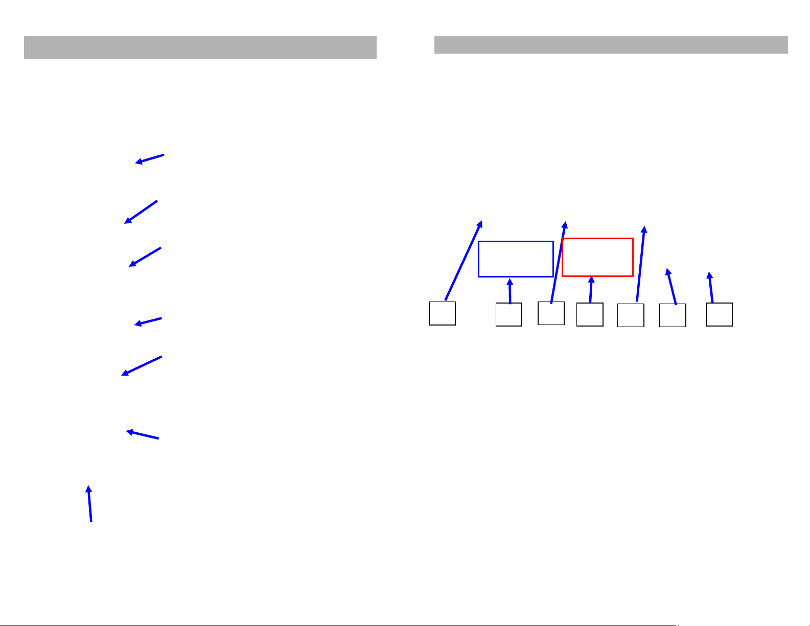
Zone Defense Trailer Coil Cable
Auxiliary Coiled Camera Cable With 2 Receptacles For
Zone Defense Camera Cables. Part # 0359A2
3
SAFETY INFORMATION
Before installing and operating read manual
Important! – Please Read This Manual Before Installing!
Congratulations on the purchase of your Zone DefenseTM
System. Zone Defense is a leader in vehicle observation
systems. When properly installed and used, your System 327 is
designed to provide you with years of trouble-free operation. This
manual contains important information required to properly install
and operate the unit. Please read this manual thoroughly before
beginning.
All Zone Defense products are strictly intended to be installed as
a supplement and Zone Defense observation systems and/or
products are not intended for use as substitutes for rear-view
mirror devices, or for any other standard motor vehicle equipment
required to be installed on vehicles by law. Zone Defense
products contribute to improving the vehicle operator’s field of
view. Our products are no substitute for proper defensive driving
techniques, observance of traffic laws and motor vehicle safety
regulations.
Warnings!
Installation Location
It is unlawful in most jurisdictions for any person(s) to drive a
motor vehicle equipped with a television viewer/screen located at
any point forward of the back of the driver’s seat (or in any
location that is visible, directly or indirectly), to the driver while
operating the vehicle. The system 327 is designed to be used
primarily as a rear observation device. In any installations where
Systems 327 products are used to display television broadcasts
or recorded video playback, installation location must adhere to
local laws and regulations.
Tampering
To prevent electrical shock, DO NOT OPEN THE MONITOR
CASE. There are potentially harmful voltages inside the monitor.
There are no user serviceable parts inside any of the
components of the Zone Defense products. If tampering is
detected, the warranty will be co

4
WARNING
♦Do not place heavy object on cables or cover
them with rugs or carpet.
♦Do not place cables where they can be pinched
or stepped on.
♦Designed as a driving aid. Watching videos,
broadcasts, DVDs and/or any images other
than intended driving assistance cameras is
prohibited.
CAUTION
♦To avoid damage to electronic circuit, stop
using this product while doing welding work to
the vehicle and/or trailers.
♦Never immerse any component in water, and
do not employ spray cleaners. When cleaning,
use damp lint-free cloth only.
♦Connect this unit only to other compatible
devices.
♦Make sure all cables are connected properly;
improper cable connections may damage the
camera and the monitor.
♦Make sure all cables are connected firmly.
♦Cables should not be allowed to touch hot or
rotating parts, such as engine, ventilator, etc.
♦Do not locate the monitor near heat generating
vents or devices.
♦Turn off power to the monitor when connecting
the camera.
Monitors are not designed to be waterproof. Exposure
to water, such as rain, may damage the unit.
5
SYSTEM FEATURES
MONITOR
Display Device: 7” CRT
Input Voltage: DC 11~32V
Power Consumption: <=18W
Working Temperature: -15 C°~+60 C°
Image Resolution: >=420 TV Lines
Horizontal / Vertical Sync Resolution: CCIR, 15.625kHz (H) / 50 (V)
EIA, 15.734kHz(H) / 60Hz(V)
Anti-vibration Capability: 6.8G
Dimensions:203mm*153mm*219mm
Weight: 5kg
1 / 3” B/W CCD CAMERA SPECIFICATIONS
TV System: EIA
Effective Pixels: 512 x 492 pixels
Sensing Area: 4.9mm x 3.7mm
Scanning System: 2:1Interlace
Sync. System: Internal
Resolution: 420TV lines
Minimum Illumination: 0 Lux
Horizontal Sync resolution: 15,734KHz
Vertical Sync resolution: 60Hz
Video Output: 1.0vp-p, 75Ohm
Microphone: No
Gamma Consumption: 0.45
AGC: Auto
S/N Ratio: Better than 48dB
White Balance: Auto
Electronic Shutter: 1/60 ~ 1/10,000
BLC: Auto
Current Consumption: Max. 300mA
Power Supply: DC12V
Operating Temperature: -20°C~70°C, RH95% MAX
Storage Temperature: -40°C~85°C RH95% MAX
Lens: f = 2.8
Lens Angle: (Standard 120°may vary based on specifications requested)

6
SYSTEM COMPONENTS
Part Quantity
7” CRT B/W Monitor 1
Camera 1
Monitor support bracket 1
Support bracket mounting screw 4
Power cable 1
Manual 1
Angle adjustment screw 4
Camera cable 1
Monitor support
Bracket
Angle adjustment
screw
Support
mounting screw
Power Cable Vibration pad
Camera Cable
Manual Camera
7
SYSTEM COMPONENTS
This monitor can be mounted in dash, hanging or seating in
any position, which ever is suitable to the driver to observe the
images. Take care not to block any necessary viewing area
when mounting.
Mounting Monitor
1. After determining the monitor location, position the monitor
support bracket, mark the bolthole location and then drill the
holes. Be careful not to drill into any other surface that may be
hidden.
2. If supplied, use washers on mounting screws. Attach monitor
bracket. Check installation before mounting monitor.
3. Mount the monitor to the support bracket with supplied 4 angle
adjustment screws.
4. Connect one end of the power
cable (wire) to the proper
connections. Connect the other end
of the power cable (plug) to the
monitor; connect the monitor and
the camera with the system
connecting cable.
Camera Mounting
Grommet
Waterproof Camera
Connectors
Secondary Waterproof Sleeve
Slides Over Connection
5/8-inch hole needed to pass connector through the
exterior wall. Be careful not to drill a hole so large that the
grommet will not seal. Before drilling make sure there are
no obstacles in the way in the drill bit. Check to make
sure wall thickness is suitable for weatherproofing
grommet. Use proper hardware to mount camera bracket.

8
SYSTEM OPERATIONS
Control Panel Display
1. ON/Off Power button
2. Camera 1 - 4 selection switch
3. Day/Night button: adjust
brightness level with push of
button.
4. Volume
5. CONT. (Contrast) button:
enhance contrast with
clockwise rotation, to reduce
use counterclockwise
rotation.
6. BRIT. (Brightness) button:
Enhance brightness with
clockwise rotation, to reduce
use counterclockwise
rotation.
7. Mode: auto position turns system on when power
is activated. Manual mode requires the On/Off
switch to activate.
9
CONNECTION OPERATIONS
1. Camera 1 input
2. Audio / Video Input
3. Camera 2 input
4. Audio / Video Output
External Speaker Jack
5. Camera 3 input
6. C1-C4 Normal / Mirror image switch
(Up is mirrored / down is normal)
7. Power Plug
Power cable connections:
1. Red to 12V DC power input
2. Orange to reversing, automatically powers camera 1
(to backup light wire, turns on camera one when energized)
3. White to headlight switch, for auto dimming
4. Black to ground (GND)
System 27 can be linked to 4 channels of cameras as well as 1 channel of
video/audio output, which can be connected to a video recorder device for
recording images.
1
2
3
4
5
6
7

10
TECHNICAL SUPPORT
Trouble Shooting Chart
Symptom
Cause
Solution
Rolling image Monitor (horizontal
hold)
Adjust horizontal
control
Small & Unstable
image
Monitor improper
voltage
Check the voltage of
power supply
Black image Monitor improper
voltage
Check fuse, check
power cable, wires or
connections (look for
loose or broken wires).
White image Monitor/Camera Check main system
cable. Make sure
all connectors are
connected properly.
If ok, check 4 pin
camera /monitor cable.
Blurred image Dirty camera lens Clean camera lens.
Engine noise or
Static lines
Monitor Check ground and
+12V DC source.
No light displayed
on monitor
Broken fuse or low
brightness level
Check whether the fuse
is broken or the
brightness knob has
been turned to the
lowest level
No image No power or
unplugged
connector
Check power and
check for unplugged or
broken camera cable
Technical Support
For help with Zone Defense technical support, please email us.
Email: techsupport@ZoneDefenseTruck.Com
techsupport@ZoneDefenseRV.Com
Phone support: (866) 672-1212
RV Parts/Sales Inquiries Sales@ZoneDefenseRV.Com
Trucking Parts/Sales Inquires Sales@ZoneDefenseTruck.Com
11
NOTES
Optional Equipment
Cigarette Lighter Pedestal
Monitor Mount - Part # 400B
Cigarette lighter monitor pedestal plugs
into the 12v accessory outlet.
Windshield Pedestal
Monitor Mount - Part # 400A
E-Z Windshield Mount allows for the
monitor to be removed when not in
use.
Zone Defense Truck Coil Cable
Part # 0359A2
Auxiliary Coiled Camera Cable With 2
Receptacles
Zone Defense Camera Cables
20 Meter Cable Part #358
15 Meter Cable Part #358A
10 Meter Cable Part #358b
Color Camera - Part # 312-313C
Optional I/R Color camera w/ cables
and 5m camera Cable
Dome Camera
Part # 312-313D
Color infrared camera w/ adjustable
angle view 5m camera Cable
RV Security Camera Part # 312-313C
Mounts outside and plugs into TV’s
RCA jacks. Night-vision, audio, color
Table of contents