Zoning Zity User manual

ES
EN
FR
IT
ZITY zoning system
Technical and Installation
Manual
P.O. BOX 5
08540 Centelles (Barcelona)
T +34 93 889 80 91
www.zoning.es
Technical Support Service:
Tel. (+0034) 902 550 290

Contents
2Manual del usuario V 02/18
Connection of system components ...................................... 3
System configuration ............................................................. 4
Start-up .................................................................................... 5
System description ................................................................. 7
Connection of components ................................................. 10
System configuration ........................................................... 18
Start-up .................................................................................. 24
Most common errors ............................................................ 26
Technical characteristics ..................................................... 27
WEE (WEEE)
Do not dispose of Electrical and Electronic Devices as household waste.
These devices should be taken away for recycling. Act according to the
legislation in force.
Quick installation guide
Detailed installation manual
NOTES ON RADIO TRANSMISSION
The central control unit should preferably be located in a high place and away from metal masses and conductive
elements. Otherwise, the range between the thermostats and the central control unit may be reduced.
Radio transmission does not take place on an exclusive frequency, so the possibility of interference cannot be
excluded. Frequency inhibitors and radio equipment operating in a permanent transmission mode in the same
frequency band (433 MHz) may impair the normal operation of the ZONING. The system is designed to work on two
different frequencies (433.92 and 434.33 MHz) to minimise this type of problem.
The installation should be carried out by authorised personnel only. Perform the entire
installation without supply voltage. Protect the equipment with the usual devices.

ZITY, quick installation guide (for air zoning systems)*
v 0.V 02/18 TAGBASE 3
ES
A Connection of system components
First of all, install and connect all system components, taking the following diagrams into account:
Fig. 1 Installation diagram for DIRECT EXPANSION, system with 4 zones (2 radio ZOE-RC + 2 wired ZEBRA) + communication interface
Fig. 2 Installation diagram for 2-PIPE FAN-COIL, system with 4 zones (2 radio ZOE-RC + 2 wired ZEBRA)
To AC unit
See gateway manual
* Maximum of 2 gate valves per zone
* Only for
installations
without gateway
Sensor
* Maximum of 2 gate valves per zone
Sensor
To Fan-Coil
units
A: 2-Pipe Fan-Coil B: 4-Pipe Fan-Coil
(*) For other types of installation (boiler, hybrids, VRV, etc.), see the relevant section
in the detailed manual.

ZITY Central control unit
4Manual del usuario V 02/18
The components to be installed in the system are as follows:
1Zone gate valves: connect the gate valves to the Zone
Outputs 1 to 6, respecting the polarity (Red: +, Black: -).
2Thermostats:
–Via radio: they do not require any wiring, only
requires the installation of batteries in the
thermostats.
–Via wires: they operate via Bus and are supplied
directly from the central control unit:
Connect the power supply wires to the “DC Power
Output 12V” terminal, respecting the polarity
(Orange: -, Blue: +)
Connect the communication wires to the “Rs485/
Loc” terminal, respecting the polarity (Red: A,
Black: B).
3Air return sensor: connect it to output NTC2.
4Air conditioning unit:
–In "Direct Expansion” installations, follow the
instructions in the "Interface Manual" for the relevant
brand and model.
–In "Water-operated Fancoil” installations, make the
connections according to the type of installation (2T,
4T, conventional or inverter fan).
5ZITY module power supply: connect the power supply to
the corresponding 230VAC/50Hz/1 terminals.
B System configuration
After connecting the components, configure the system:
1First of all, connect the thermostats to the central control unit and the corresponding zone:
–associate each thermostat with the central control
unit (with the identification number ID)
–assign a zone number to each thermostat
(corresponding to the motorised valves connected to
outputs 1 to 6 of the central control unit)
The thermostats are connected by using the settings menus for each thermostat:
•ZOE-RC thermostat (communication by radio)
ZEBRA thermostat connection diagram
+12VDC: blue wire
-12VDC: orange wire
A: red wire
B: black wire
ID
Z
MASTER
MASTER
OFF
OFF
ON
ON
SYST
SYST
ECO
PROG
PROG
1 2 3 4 567
2468
10
10
12
12
14
14
16
16
18
18
20
20
22
22
24
24
ºC
TIMER
TIMER
Z
MASTER
MASTER
OFF
OFF
ON
ON
SYST
SYST
ECO
PROG
PROG
1 2 3 4 567
2468
10
10
12
12
14
14
16
16
18
18
20
20
22
22
24
24
ºC
TIMER
TIMER
Z
MASTER
MASTER
OFF
OFF
ON
ON
SYST
SYST
ECO
PROG
PROG
1234567
2468
10
10
12
12
14
14
16
16
18
18
20
20
22
22
24
24
ºC
TIMER
TIMER
SET
DAY
ON/OFF
Z
MASTER
MASTER
OFF
OFF
ON
SYST
SYST
ECO
PROG
1234567
246810 12 14 16 18 20 22 24
ºC
TIMER
TIMER
ON/OFF
Z
MASTER
MASTER
OFF
ON
ON
SYST
SYST
ECO
PROG
PROG
1234567
246810 12 14 16 18 20 22 24
ºC
TIMER
TIMER
ON/OFF
/
34
Z
MASTER
MASTER
OFF
ON
SYST
SYST
ECO
PROG
PROG
1234567
246810 12 14 16 18 20 22 24
ºC
TIMER
TIMER
/
/
2
Z
MASTER
MASTER
OFF
ON
SYST
SYST
ECO
PROG
PROG
1234567
246810 12 14 16 18 20 22 24
ºC
TIMER
TIMER
Z
MASTER
MASTER
OFF
ON
ON
SYST
SYST
ECO
PROG
PROG
1234567
246810 12 14 16 18 20 22 24
ºC
TIMER
TIMER
ON/OFF ON/OFF
/
56
1

ZITY, quick installation guide (for air zoning systems)
v 0.V 02/18 TAGBASE 5
ES
•ZEBRA thermostat (communication by wires)
2Then configure the switches (SW1) of the central control
unit according to the type of installation and the
production equipment, so that the equipment executes
the relevant control protocol. The three most common
cases are shown as examples (air-operated
installations type direct expansion / 2-pipe Fan-coil / 4-
pipe Fan-coil):
•Direct expansion:
•2-Pipe Fan-Coil:
•4-Pipe Fan-Coil:
C Start-up
1Learning mode: switch DIP8 to OFF; the system starts
up automatic recognition of all connected elements
(thermostats, interfaces, etc.).
When the LEDs in all the required zones are lit up in
green and the LED of relay R1 is not flashing, the
system will have completed all recognition.
2Normal operation: raise the DIP8 of SW1 and cut off the
power supply for 10 seconds. The system will start up
in normal mode.
3Check the following steps:
UP FAN
1
4
3
2
UP DOWN
FAN
UP DOWN UP DOWN
5
FAN
UP DOWN
x4
UP
x6
ID
ID
ID
ID
7
UP
6
DOWN
FAN
MODE
To enter the
programming:
first of all switch off the
thermostat
(if it is a slave, by press-
ing “POWER”;
if it is a master, by
pressing “POWER” con-
tinuously for around 3
seconds
once the thermostat has
been switched off, press
“MODE” continuously
for around 5 seconds
until “Pr” appears.
For more information about programming, see the ZEBRA thermostat manual
Normal mode
Learning mode
Selection of learning mode DIP8 = OFF
123 4 5
Select 18ºC on all
thermostats
Check that all
grilles open
Wait for the machine
to start from cold
Select 30ºC on all
thermostats
Check that all grilles
close and the machine
stops
Select 30ºC on all
thermostats
Check that all
grilles open
Wait for the machine
to start from warm
Select 18ºC on all
thermostats
Check that all grilles
close and the machine
stops

ZITY Central control unit
6Manual del usuario V 02/18

ZITY Central control unit, detailed installation manual
v 0.V 02/18 TAGBASE 7
ES
1 System description
The ZONING system is made up of a set of regulating
devices for temperature control in up to 18 separate zones
in centralised air conditioning and/or heating installations.
Control is achieved through a central control unit
connected to digital thermostats and motorised valves
(gate valves), installed in each of the areas to be climate-
controlled.
This central control unit regulates the temperature in each
zone acting on the relevant gate valves and the air
conditioning and/or heating unit. At the same time, the
system central control unit allows interaction with other
devices in the installation (home automation, digital input,
WIFE connection, etc.).
1.1 ZITY central control unit ––––––––––––––––––––––––––––––––––––––––––––––––––––––––––––––––––––––––––
Electronic control device for surface mounting, designed for
air condition and heating equipment from 2 to 18 areas.
ZITY can control direct expansion units, hydronic fan coils
and radiant floor or radiator heating systems.
Communication with the zone thermostats can be via radio
or wired, depending on the thermostat. It has 2 RS 485
communications ports, one local and the other remote,
which make integration possible in building management
systems.
Fig. 1 ZITY central control unit
1.1.1 ZITY-RC/M
System central control unit, which communicates with the
thermostats via radio or through cables. It is configured by
default as the MASTER with respect to the other central
units in the installation.
1.1.2 ZITY-RC/S
System central control unit, which communicates with the
thermostats via radio or through cables. In this case, it is
configured as a SLAVE of the main board. It is used in
multiple VRV or Fan coil installations with one item of
centralised production equipment.
1.1.3 ZITY-W/M
Central control unit with MASTER function over the rest of
the system boards. Communication is exclusively by
cables. It is configured by default as the MASTER with
respect to the other central units in the installation.
1.1.4 ZITY-W/S
System central control unit, which communicates with the
thermostats via cables only. It is configured as a SLAVE of
the main board. It is used in multiple VRV or Fan coil
installations with one item of centralised production
equipment.
1.1.5 ZITY/ME /MR /MC
Expansion modules for zones or relays.
1.2 Timer-thermostats –––––––––––––––––––––––––––––––––––––––––––––––––––––––––––––––––––––––––––––––
The timer-thermostats are the user interfaces for
temperature control in each of the zones, with a maximum
interval of +/- 0.5ºC.
They allow weekly programming by zone and the
adjustment of various parameters for limiting and blocking
functions.
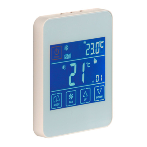
1.2.1 ZOE- RC
Digital Timer-Thermostat via radio (RC), to operate
together with the Zoning System central control units.
Integration of Master/ Slave mode in the same thermostat,
selectable through the settings menus. Weekly
programming on 2 levels (Comfort/ ECO).
ZOE-RC thermostats can be set to suit each installation,
blocking of functionalities, setpoint temperature limitation,
etc. (see settings section).
Fig. 2 ZOE-RC timer-thermostat

Installation manual
8Manual del usuario V 02/18
1.2.2 ZEBRA
Wired Timer-Thermostat (W), to operate together with the
ZITY central control unit. Two-way communication
between the central unit and the thermostat. Integration of
Master/ Slave mode in the same thermostat, selectable
through the settings menus. Weekly programming on 2
levels (Comfort/ ECO). Can be set to suit each installation,
blocking of functionalities, setpoint temperature limitation,
etc.
1.3 Interfaces
These are the communication gateways between the
Zoning system and the direct expansion air conditioning
units (see compatible models). Two-way communication
between them optimises the operation of the entire
system, allowing control of the operating mode, fan speed
adjustment and setpoint modulation according to demand
from the zones, improving both comfort and energy
consumption.
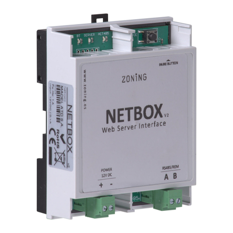
1.4 NETBOX Interface
The communication interface between the ZITY central
control unit and the CLOUD application of the ZONING
system.
Allows easy and intuitive remote control of your ZONING
system from any mobile device (smartphone, tablet) or
desktop device (PC), thanks to the responsive format
Webapp.
1.5 Motorised gate valves ––––––––––––––––––––––––––––––––––––––––––––––––––––––––––––––––––––––––––
The motorised gate valves (24 VDC) allow On/Off
regulation of the air flow in the zones.
They can be installed in a circular or rectangular duct or
directly in the drive grid.
1.5.1 ZP-AZ
Motorised gate valve with opposite fins, for Zoning System
grids. Made from aluminium and galvanised steel, with
polyamide gears and PVC seals.
1.5.2 ZC/ZR
Motorised circular gate valve with sealed closure, made of
galvanised steel, with bearings and rubber gasket. For
direct fitting in circular or plenum duct.
1.5.3 ZQ
Motorised rectangular gate valve with sealed closure,
made of galvanised steel, with bearings and rubber
gasket.
Fig. 3 ZEBRA timer-thermostat
Fig. 4 Interfaces
Fig. 5 Netbox Interface
Fig. 6 ZP-AZ motorised gate valve
Fig. 7 ZC/ZR
Fig. 8 ZQ motorised gate valve

ZITY Central control unit
v 0.V 02/18 TAGBASE 9
ES
1.6 Pressure control valves –––––––––––––––––––––––––––––––––––––––––––––––––––––––––––––––––––––––––
Devices for controlling the overpressure generated in the
duct network due to the opening and closing of the different
gate valves in the zone.
This type of system should be installed when the
modulation of the fan speeds controlled by the interfaces is
not sufficient for compensating for the excess pressure in
the installation.
Its use is MANDATORY if no communication interface is
fitted.
1.6.1 Mechanical overpressure gate valves
Adjustable by means of a counterweight. They provide fast
and easy adjustment of the pressure variations due to
closure of the gate valves in the zone.
1.6.1.1 ZS
Overpressure gate valves adjustable by means of a
counterweight, for wall mounting.
1.6.1.2 ZK
Overpressure gate valves adjustable by means of a
counterweight, for circular duct mounting.
1.6.1.3 ZG
Overpressure gate valves adjustable by means of a
counterweight, for rectangular duct mounting.
1.6.2 Electronic pressure control unit
Electronically-adjustable constant pressure control unit,
formed by a KBY control module and a 24 VDC motorised
gate valve.
It provides accurate adjustment of the pressure variations
due to closure of the gate valves in the zone. It should be
installed when the modulation of the fan speeds controlled
by the interfaces is not sufficient for compensating for the
excess pressure in the installation.
This system is recommended for complex duct networks or
medium-high pressure equipment.
1.6.2.1 KBY
Constant electronic pressure controller
Provides a 0-10V or PWM 24 Vdc output to activate the
pressure control motorised gate valves.
1.6.2.2 Motorised gate valves
The motorised gate valves used are models ZP-AZ, ZC/ZR
and ZQ, which are described in the section “1.5 Motorised
gate valves”.
Fig. 9 ZS mechanical overpressure gate
valve
Fig. 10 ZK mechanical overpressure gate
valve
Fig. 11 ZG mechanical overpressure
gate valve
Fig. 12 Electronic pressure controller

Installation manual
10 Manual del usuario V 02/18
2 Connection of components
All system components are wired to the central control unit
or to its expansion modules.
It is advisable to locate the equipment preferably in a high
place away from metal masses and conductive elements,
place the control unit in a protected place that can only be
accessed by authorised personnel and with the
appropriate tools for opening and subsequent handling of
the equipment in question.
Attachment to the wall can be with screws (by lifting the
rear pins of the box) or by means of the anchors for DIN
rail.
Fig. 14 Connection of all ZONING SYSTEM components in the ZITY control unit
2.1. Power supply
Supplies the central control unit at 230 VAC through the
“Power Supply (1)” terminals, using wires with a section of
between 1.0 mm2and 1.5 mm2.
2.2. Aerial
Only for equipment via radio ZITY-RC: screw in the aerial
supplied (4) and position it in the false ceiling in the best
position to receive the radio signal.
2.3. Motorised gate valves
Connect the motors of each regulator to terminal strips 1 to
6 on the board (7). Use a red (+) / black (-) wire with a
section of between 0.75 mm2and 1.0 mm2. If there are two
regulators per zone (maximum recommended), connect
them in parallel.
In installations with more than 6 zones, 1 or 2 zone
expansion modules will be connected. The first expansion
module controls zones 7 to 12. A third module can be
added, which will control from zone 13 to zone 18. The
connection of these modules will take place through the
RS485 local bus of the equipment.
Fig. 13 ZITY central control unit: attach with screws or via DIN rail
1 Supply voltage, (230VAC/ 50 Hz/ 1)
2 NTC temperature sensors (see
location according to type of
equipment)
3 Output voltage of 12 VDC, for wired
thermostats
4 433/434 MHz radio transmission
antenna (only in ZITY-RC central
control units)
5 RS485 local communication bus.
For wired thermostats and
expansion modules
6 RS485 local communication bus, for
communication with equipment
interfaces (connect in parallel with
the previous bus)
7 RS485 remote communication bus
for home automation
communication or BMS (MODBUS
RTU-SLAVE protocol)
8 24 VDC outputs for control of zone
motorised gate valves (maximum 2
gate valves per zone)
9 Control relays of the air conditioning
equipment (see connection
depending on the type of
equipment)

ZITY Central control unit
v 0.V 02/18 TAGBASE 11
ES
Fig. 15 Control of up to 18 zones through three ZITY control centres
Interconnection with the equipment, NTC sensors, digital
inputs, etc., will only take place from the ZITY basic board
(outputs 1 to 6). The expansion modules only manage the
zones.
2.4. Thermostats ––––––––––––––––––––––––––––––––––––––––––––––––––––––––––––––––––––––––––––––––––
Distribute the thermostats in a prominent place in each of
the zones to be climate-controlled.
Place at a height of approximately 1.5 m, avoiding direct
heat sources and unwanted air currents.
2.4.1 ZOE-RC Thermostats
Thermostats with communication via radio: insert the
batteries supplied with the equipment. They do not require
any additional wiring.
2.4.2 ZEBRA Thermostats
Thermostats with communication via wires: the two power
supply wires should be connected (orange/ blue: 12VDC)
and the 2 communication wires (red/black), according to
the diagram opposite.
2.5. Production equipment and NTC probes ––––––––––––––––––––––––––––––––––––––––––––––––––––––––––––
The ZITY zoning system is compatible with climate-control
installations via air ducts (direct expansion or Fan coil) and
hybrid systems with air conditioning and heating by
radiators.
The interconnection between the central control unit and
the production equipment varies according to the type of
installation, the combination between them and the
functionalities required by the user.
In addition, the ZITY central unit has 2 sensor inputs (NTC
1 and NTC 2), whose function depends on the production
equipment installed:
•NTC 1: return air temperature sensor in direct
expansion installations or water intake temperature
sensor in fan coil installations with 4 pipes.
•NTC 2: water temperature sensor in fan coil
installations with 2 hybrid pipes. Or return temperature
sensor in direct expansion installations.
Fig. 16 ZEBRA thermostat connection diagram
+12VDC: blue wire
-12VDC: orange wire
A: red wire
B: black wire

Installation manual
12 Manual del usuario V 02/18
2.5.A. Air duct air conditioning systems
2.5.A.1. Direct expansion equipment with interface
The ZITY central control unit is connected to the air
conditioning equipment with a communication interface
from the corresponding brand (see models available).
Allows automatic fan speed management according to the
zones in demand, summer/winter mode change for master
thermostat of the installation and optimisation of the
operation of the inverter.
Fig. 17 Standard installation diagram for equipment with interface
See the interface manual for each brand for detailed
connection and settings.
The NTC2 sensor is used to measure the return air
temperature in the Interfaces that cannot read this value via
communications.
The internal unit control is not mandatory but it is advisable
to install it as an alarm display for the air conditioning
equipment.
2.5.A.2. ON/OFF direct expansion equipment
In older units that are not compatible with the interfaces,
the unit control relays can be used for remote start/stop.
The functionalities and output of the zoning system without
interface are lower than those of systems that do have it,
but they allow basic control of the air conditioning
equipment.
Fig. 18 Standard installation diagram for equipment without interface
See the connection diagram for each brand and model. It is
mandatory to install the internal unit control for controlling
the operating mode and setpoint temperature of the
equipment.
The NTC2 sensor is used for safety reasons and it is only
mandatory to install it in electromechanical equipment. In
all other cases the heating element that comes by default
from the factory can be left in place.

ZITY Central control unit
v 0.V 02/18 TAGBASE 13
ES
2.5.A.3. VRF 2T direct expansion equipment with imposition of operating mode by VRF Master Equipment
Fig. 19 VRF direct expansion with imposition of operating mode by VRF Master Equipment
2.5.A.4. VRF 2T direct expansion equipment with imposition of Last Order operating mode
Fig. 20 VRF direct expansion with imposition of Last Order operating mode
In this case, each internal
unit is connected to the
corresponding ZITY central
control unit, as in the direct
expansion equipment with
interface.
To manage the operating
modes of the various VRF
internal units (in systems with
2 pipes) the central control
unit connected to the Master
equipment should be
configured as VRF Master,
while the rest of the central
control units connected to the
other units will be declared
VRF Slaves.
To do this, use the DIP 5 of
SW1 of the ZITY central
control unit.
Each internal unit is
connected to the
corresponding ZITY
central control unit, as in
the direct expansion
equipment with interface.
In this case any internal
Unit of the VRF system is
able to impose the mode.
In this application all ZITY
central control units con-
nected to each internal
unit should be configured
as VRF Master.
To do this, use the DIP 5
of SW1 of the ZITY central
control unit.
For other settings and
connections with the VRF
systems, consult the tech-
nical department.

Installation manual
14 Manual del usuario V 02/18
2.5.A.5. Fan-coil 2T hydronic equipment, 0-10V Inverter fan control
The ZITY central control unit is directly connected to the
fan-coil and to the 2-tube battery valve. The KBY system
controls constant pressure via the inverter fan through the
0-10 V output.
The NTC1 sensor is connected to the intake pipe of the fan-
coil to detect the water temperature. This avoids starting up
the fan at undesired temperatures.
Fig. 21 Fan-coil 2T, 0-10V Inverter fan control
2.5.A.6. Fan-coil 2T hydronic equipment, 3-speed fan control
The system is directly connected to the fan-coil and to the
2-tube battery valve.
No additional equipment control is required.
As in the previous case, the NTC 1 sensor is connected to
the fan-coil intake pipe.
Fig. 22 Fan-coil 2T, 3-speed fan control
2.5.A.7. Fan-coil 4T hydronic equipment, 0-10V Inverter fan control
The system is directly connected to the fan-coil and to the
4-tube battery valve.
The KBY system controls the inverter fan at constant
pressure through the 0-10 V output.
In 4 T installations the 2 sensors should be connected. NTC
1 measures the hot water temperature and NTC 2 the cold
water temperature.
Fig. 23 Fan-coil 4T, 0-10V Inverter fan control

ZITY Central control unit
v 0.V 02/18 TAGBASE 15
ES
2.5.A.8. Fan-coil 4T hydronic equipment
The system is directly connected to the fan-coil and to the
4-tube battery valve.
No additional equipment control is required.
The NTC sensors perform the same function as in the
previous case.
Fig. 24 Fan-coil 4T
2.5.B. Water-operated heating equipment and hybrid heating/direct expansion equipment
2.5.B.1. Water-operated heating
Allows zoning of a conventional heating installation, by
radiators or radiant floor.
The system manages the thermostatic zone valves on the
one hand and, on the other the boiler start/stop.
The NTC sensors are used as protection against discharge
temperatures that are too high or too low.
NTC 1 is used for the boiler and NTC 2 for the radiant floor
temperature.
Fig. 25 Water-operated heating
* The accessories for regulating the hydraulic system may vary depending on the type of
installation (radiant floor, radiators, with or without pump, etc.)

Installation manual
16 Manual del usuario V 02/18
2.5.B.2. Combined heating / direct expansion hybrids
In this application it is possible to control a conventional
heating system and at the same time an air conditioning
unit by direct expansion with Interface, integrating in a
single type of thermostat all the functionalities of both
systems separately.
Two ZITY central control units are installed, one to control
the direct expansion unit (with or without gateway) and the
other to control the heating system by radiators or radiant
floor.
Both central control units are joined by a Communication
Bus, which manages either central control unit depending
on the operating mode (Cold/heat by air, or radiant heat).
The first one is defined as the Master Central Control Unit
and the second one as Slave.
The NTC sensors have the functionality of each of the
production equipment separately.
Fig. 26 Combined heating / direct expansion
2.5.C. Hybrid aerothermal heating / water-operated air conditioning equipment
The same installation can combine water-operated heating
systems with radiators and/or radiant floor and fan-coils
with ducts for controlling air conditioning and/or air-
operated heating.
2.5.C.1. Water-operated heating and 3v Fan-coil with 2 pipes
Two ZITY central control units are installed, one for
controlling the Fancoil with ducts by zone and the other for
the heating system by radiant floor or radiators.
As in the previous case, the board that controls the fan-coil
is configured as the MASTER and the one that controls the
heating is configured as the SLAVE. With this configuration
the MASTER is the one that acts on the internal Unit of the
Aerothermal equipment to produce the ON/OFF and also
set the operating mode. This control takes place via 2
voltage-free contacts. Consult the wiring diagram for each
Aerothermal brand and model.
Consult Madel for other Aerothermal applications and
settings.
* The accessories for regulating the hydraulic system may vary depending on the type of installation (radiant floor, radiators, with or without pump,

ZITY Central control unit
v 0.V 02/18 TAGBASE 17
ES
Fig. 27 Water-operated heating and 3v Fan-coil with 2 pipes
2.6. RS485 / Loc ––––––––––––––––––––––––––––––––––––––––––––––––––––––––––––––––––––––––––––––––––
RS485 internal communication bus between the various
elements of the zoning system. The following items are
connected to it:
•ZEBRA wired thermostats
•Communication interfaces with direct expansion units
•Zone extension modules
•ZITY slave boards for combined installations.
This bus owns the ZITY system and it should only be used
for the items described above, do not connect it to any other
external communication system.
2.7. RS485 / Rem –––––––––––––––––––––––––––––––––––––––––––––––––––––––––––––––––––––––––––––––––
RS485 remote bus for communication between the ZITY
system and other items of the installation in the home or
building. Communication via Modbus RTU.
Request the specific documentation and the memory map
for communication with the RS485/Rem port.
Non-combined system

Installation manual
18 Manual del usuario V 02/18
3 System configuration
The system configuration consists of two steps:
1Connect the thermostats to the central control unit and
the corresponding zone
2Configure the switches of the ZITY central control unit
according to the type of installation
3.1. Connect the thermostats
This consists of associating each thermostat
with the central control unit (with the
identification number ID of the central control
unit) and assigning it a zone number
(corresponding to the motorised gate valves
connected to outputs 1 to 6 of the central
control unit).
These operations will be carried out via the
settings menus of each thermostat, as
indicated below. You can find additional
information in the thermostat instruction
manuals.
3.1.A. ZOE-RC thermostat (communication via radio)
Fig. 29 Basic configuration of the ZOE thermostat: ZITY model central control unit, central control unit ID number, zone number and master/slave
3.1.B. ZEBRA thermostat (communication by wires)
Fig. 30 Basic settings of the ZEBRA thermostat: master/slave and zone No.
Fig. 28 Identification number ID of the central control unit
Z
MASTER
MASTER
OFF
OFF
ON
ON
SYST
SYST
ECO
PROG
PROG
1 2 3 4 567
2468
10
10
12
12
14
14
16
16
18
18
20
20
22
22
24
24
ºC
TIMER
TIMER
Z
MASTER
MASTER
OFF
OFF
ON
ON
SYST
SYST
ECO
PROG
PROG
1 2 3 4 567
2468
10
10
12
12
14
14
16
16
18
18
20
20
22
22
24
24
ºC
TIMER
TIMER
Z
MASTER
MASTER
OFF
OFF
ON
ON
SYST
SYST
ECO
PROG
PROG
1234567
2468
10
10
12
12
14
14
16
16
18
18
20
20
22
22
24
24
ºC
TIMER
TIMER
SET
DAY
ON/OFF
Z
MASTER
MASTER
OFF
OFF
ON
SYST
SYST
ECO
PROG
1234567
246810 12 14 16 18 20 22 24
ºC
TIMER
TIMER
ON/OFF
Z
MASTER
MASTER
OFF
ON
ON
SYST
SYST
ECO
PROG
PROG
1234567
246810 12 14 16 18 20 22 24
ºC
TIMER
TIMER
ON/OFF
/
34
Z
MASTER
MASTER
OFF
ON
SYST
SYST
ECO
PROG
PROG
1234567
246810 12 14 16 18 20 22 24
ºC
TIMER
TIMER
/
/
2
Z
MASTER
MASTER
OFF
ON
SYST
SYST
ECO
PROG
PROG
1234567
246810 12 14 16 18 20 22 24
ºC
TIMER
TIMER
Z
MASTER
MASTER
OFF
ON
ON
SYST
SYST
ECO
PROG
PROG
1234567
246810 12 14 16 18 20 22 24
ºC
TIMER
TIMER
ON/OFF ON/OFF
/
56
1
UP FAN
1
4
3
2
UP DOWN
FAN
UP DOWN UP DOWN
5
FAN
UP DOWN
x4
UP
x6
ID
ID
ID
ID
7
UP
6
DOWN
FAN
MODE
To enter the
programming:
first of all switch off the
thermostat
(if it is a slave, by press-
ing “POWER”;
if it is a master, by
pressing “POWER” con-
tinuously for around 3
seconds
once the thermostat has
been switched off, press
“MODE” continuously
for around 5 seconds
until “Pr” appears.
For more information about programming, see the ZEBRA thermostat manual

ZITY Central control unit
v 0.V 02/18 TAGBASE 19
ES
3.2. Configure the central control unit
The switch SW1 is used to configure the ZITY central control unit
according to the type of installation and operating frequency.
The DIP 8 is used to position the equipment in learning mode during
start-up of the installation (see the corresponding section).
In green, the default position of the dips
Consult the diagrams for each type of installation to see the
combination of the different DIPs.
For remote connections with BMS, combined installations
between Master/ Slave boards, consult the technical
department.
Fig. 31 SW1, to configure the ZITY central control unit
Switch SW1 Description
1 2 3 4 5 6 7 8
↑x x x x x x x The production equipment is water-operated
↓x x x x x x x The production equipment is Direct Expansion (DX) (default option)
x↑x x x x x x Internal Fan-coil type unit
x↓x x x x x x DX internal unit (Split or VRV) or Boiler if SW1 is ON (by default)
xx↑xxxxxCentralised system. The equipment only obeys the commands that reach it from
the RS485/Rem bus
xx
↓xxxxxDistributed system. The equipment obeys the last order that arrives, whether from
the RS485/Rem bus or from the thermostats. Without any priority. (default option)
xxx↑xxxxRadio transmission frequency 433 Mhz. Corresponds to Fr00 of the ZOE-RC
thermostats
xxx
↓xxxxRadio transmission frequency 434 Mhz. Corresponds to Fr01 of the ZOE-RC
thermostats (default option)
xxxx↑xxxFor DX installation (DIP 1 OFF) board defined as mode Slave in VRV installations.
For Water-operated installation (DIP 1 ON) 2-pipe installation defined.
xxxx
↓xxx
For DX installation (DIP 1 OFF) board defined as mode Master in VRV
installations. (default option)
For Water-operated installation (DIP 1 ON) 4-pipe installation defined.
xxxxx↑xxThe operating mode is defined by a Remote system via the RS485/Rem remote
bus.
xxxxx
↓xxThe operating mode is locally defined by the Master thermostat of the system.
(default option)
xxxxxx
↑xNot combined. There is a single item of production equipment; air or water. (by
default)
xxxxxx↓x Combined. Items of air and water production equipment are combined.
xxxxxxx↑Equipment in operating mode.
xxxxxxx↓Equipment in learning mode. For start-up of the installation

Installation manual
20 Manual del usuario V 02/18
3.3. Advanced settings of thermostats
Both ZOE and ZEBRA timer-thermostats have an expert
menu for setting various system parameters.
3.3.A. ZOE, expert mode settings (menu SE2)
Advanced settings have the following menus:
•Fr00: 433 / Fr01: 434 (radio frequency)
•tC00: setpoint / tC01: ambient + setpoint
•HC00: cold, heat, boiler / HC01: cold only / HC02: heat
only /HC03: boiler only
•Pr00: with timer programming / Pr01: without timer
programming
•bL00: without locking / bL01: complete locking except +/
-/ON/OFF / bL02: mode locking /“bL03: Master and
mode OFF
•Fn00: with fan active / Fn01: without fan active
•Maximum and minimum temperatures (for both heat
and cold).
Fig. 32 ZOE thermostat advanced settings
Z
MASTER
MASTER
OFF
OFF
ON
ON
SYST
SYST
ECO
PROG
PROG
1 2 3 4 567
2468
10
10
12
12
14
14
16
16
18
18
20
20
22
22
24
24
ºC
TIMER
TIMER
Z
MASTER
MASTER
OFF
OFF
ON
ON
SYST
SYST
ECO
PROG
PROG
1 2 3 4 567
2468
10
10
12
12
14
14
16
16
18
18
20
20
22
22
24
24
ºC
TIMER
TIMER
MA
SMASTER
OFF
OFF
ON
ON
SYST
SYST
EC
O
PROG
PROG
1 2 3 4 567
2468
10
10
12
12
14
14
16
16
18
18
20
20 222 24
TIMER
TIMER
Z
MASTER
MASTER
OFF
OFF
ON
ON
SYST
SYST
ECO
PROG
PROG
1234567
2468
10
10
12
12
14
14
16
16
18
18
20
20
22
22
24
24
ºC
TIMER
TIMER
SET
DAY ON/OFF
Z
MASTER
MASTER
OFF
OFF
ON
SYST
ECO
PROG
1234567
246810 12 14 16 18 20 22 24
ºC
TIMER
TIMER
Z
MASTER
MASTER
OFF
ON
ON
SYST
ECO
PROG
1234567
246810 12 14 16 18 20 22 24
ºC
TIMER
TIMER
ON/OFF ON/OFF
//
234
Z
MASTER
MASTER
OFF
ON
SYST
ECO
PROG
1234567
246810 12 14 16 18 20 22 24
ºC
TIMER
TIMER
/
Z
MASTER
MASTER
OFF
OFF
ON
SYST
ECO
PROG
1234567
246810 12 14 16 18 20 22 24
ºC
TIMER
TIMER
Z
MASTER
MASTER
OFF
ON
ON
SYST
ECO
PROG
1234567
246810 12 14 16 18 20 22 24
ºC
TIMER
TIMER
ON/OFF ON/OFF
//
567
Z
MASTER
MASTER
OFF
ON
SYST
ECO
PROG
1234567
246810 12 14 16 18 20 22 24
ºC
TIMER
TIMER
/
ON/OFF
Z
MASTER
MASTER
OFF
ON
ON
SYST
ECO
PROG
1234567
246810 12 14 16 18 20 22 24
ºC
TIMER
TIMER
ON/OFF
/
Z
MASTER
MASTER
OFF
OFF
ON
SYST
ECO
PROG
1234567
246810 12 14 16 18 20 22 24
ºC
TIMER
TIMER
Z
MASTER
MASTER
OFF
ON
ON
SYST
ECO
PROG
1234567
246810 12 14 16 18 20 22 24
ºC
TIMER
TIMER
ON/OFF ON/OFF
//
8910
Z
MASTER
MASTER
OFF
ON
SYST
ECO
PROG
1234567
246810 12 14 16 18 20 22 24
ºC
TIMER
TIMER
/
Z
MASTER
MASTER
OFF
ON
ON
SYST
ECO
PROG
1234567
246810 12 14 16 18 20 22 24
ºC
TIMER
TIMER
ON/OFF
ON/OFF
/
11 12
MIN
MAX
MIN
MAX
Z
MASTER
MASTER
OFF
ON
SYST
SYST
ECO
PROG
PROG
1234567
246810 12 14 16 18 20 22 24
ºC
TIMER
TIMER
13
ON/OFF
1
Other manuals for Zity
2
Table of contents
Other Zoning Air Handler manuals