Coverage area
In optimum conditions, the range of the detector is up to approx. 12
m ahead.
The range is dependent on the installation location and the direction of
movement.
As themotion detector reacts to temperature fluctuations between
the heat source and ambient temperature, the range can vary depending
on the installation location.
Locating the coverage area
Tilt the detector and/or cover the parts of the switching device that are
not required or cause faulty operation with adhesive tape (electrical or
masking tape).
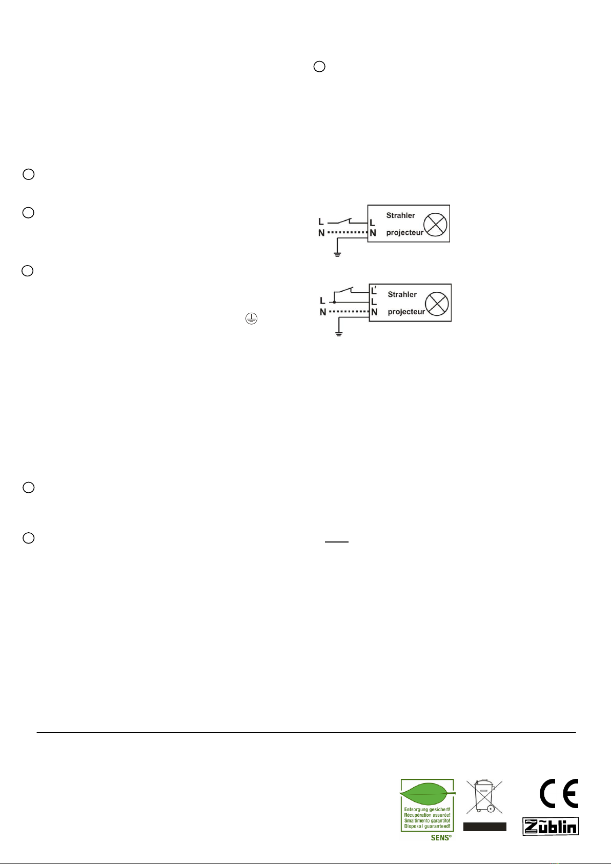
Connection diagrams
Function: The motion sensor reacts to heat omitted by moving bodies. If
a person moves towards the monitored area, the light automatically
switches on. If the person leaves the area, the light turns itself off after a
preset amount of time (approx. 3 seconds tomax. 30 minutes).
Warning! Any work to the 230V network must only be completed by
trained specialists. The product must be installed in accordance with
country-specific installation guidelines/standards.
Before starting to install the device, ensure that the 230-volt power
supply cable is de-energised using a voltage tester.
Positioning
The installation height should be approx. 2.3 m (max. 3.5 m). It must not
be installed in the vicinity of heat sources or reflective surfaces.
Installation
For installation purposes, draw three drill holes in the desired position on
the wall. Drill holes appropriate for the diameter and depth of the supplied
plugs. Firmly press the plugs into the holes. Secure the upper middle
screw and attach the device to it. Then fix the device into place using
the two remaining screws.
Power supply:
The connection must be a 230V/50Hz mains power supply! The power
supply cable is fed into the device from the rear.
The cables must be attached to the clamps as follows:
Phase/outer conductor (L): brown;
Neutral/neutral conductor (N): blue; Earth: green/yellow
Optional:
Switching output/switched phase/outer conductor (L') white;
(for parallel bypass (continuous light) or for additional loads)
Following connection to the mains power supply, the detector needs
approx. one minute before it is ready for operation. If the power supply is
interrupted (min. two seconds) then the light can be activated remotely.
Connecting electrical loads
High starting currents shorten the service life of the relay integrated into
the detector. Please observe the technical specifications provided by the
light and lamp manufacturers to ensure the relay is not overloaded.
We therefore recommend that you only use a maximum of two lights in
parallel or connect one further light without a sensor. If the switching
capacity is higher, the additional load can be switched via an external
relay.
Aligning the light and detector
Align the light and detector to suit your requirements.
The detector can be tilted by 45°.
The light can be turned by +/-10° and adjusted vertically by 10°.
Settings
Test: To ensure the functionality of the sensor can be checked during the
day and the frontal range can be adjusted, the twilight setting must be set
to "day/sun".
Timer setting
The timer can be used to determine how long the light will remain on
following the last movement in the coverage area.
Switch from minimum to maximum stop position
(turn clockwise: 3 seconds to 30 minutes).
Twilight setting (lux)
The twilight sensor regulates the operating threshold (light value) of the
motion detector determining when the device should be activated.