ZUPAN ZM 100 SN User manual

d.o.o.
Podjetje za proizvodnjo , trgovino in storitve
Celestrina 3 , 2229 MALEČNIK , Slovenija
Tel.: +386 ( 2 ) 471 60 50, 471 60 54
Fax : +386 ( 2 ) 471 60 51
TRR: 04515 - 0000191307
ID za DDV : SI16934733
www.zupan.si E-Mail: zupan.maribor@siol.net
Št.reg. 1/1357/00, Okr.sod. v Mariboru, mat.št. 5332338,osn.kapital 111.733,00 €
®
Operator` s manual
Carried sprayer
ZM 100 SN, ZM 200 SN
Before starting operation,
please carefully read and
adhere to this instruction
manual and safety advice.
Keep for future users.

PAGE 2 MAJ-14
CONTENT: PAGE:
1. INTRODUCTION................................................................................................................................. 3
2. GENERAL SAFETY ADVICE .............................................................................................................. 4
3. SAFETY SYMBOLS............................................................................................................................. 4
4. DESCRIPTION .................................................................................................................................... 6
5. ASSEMBLY.......................................................................................................................................... 7
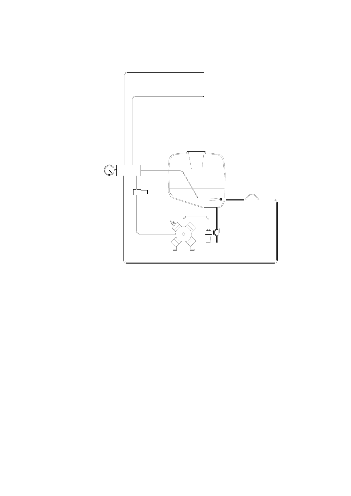
6. WORKING PRINCIPE OF THE SPRAYER......................................................................................... 9
WORKING SCHEME OF THE SPRAYER..................................................................................... 10
7. BEFORE THE USAGE ...................................................................................................................... 10
8. PREPARATIONS FOR THE WORK ................................................................................................. 11
8.1. CONNECTING THE SPRAYER ............................................................................................. 11
8.2. P.T.O. CHOICE....................................................................................................................... 11
8.3. CHOOSING THE RIGHT P.T.O. LENGTH............................................................................. 11
8.4. GREASING THE P.T.O. ......................................................................................................... 13
9. FILLING AND EMPTYING THE TANK.............................................................................................. 13
10. HOW TO USE THE REMOTE UNIT ...............................................................................................14
11. WORKING WITH THE SPRAYER.................................................................................................. 15
12. CLEANING THE SPRAYER............................................................................................................ 16
12.1. REMOVING THE TECHNICAL LEFTOVER......................................................................... 16
12.2. CLEANING THE INTERIOR ................................................................................................. 16
12.3. CLEANING THE EXTERIOR OF THE SPRAYER................................................................ 16
13. CALCULATING THE AGENT CONSUMPTION ON A HECTARE..................................................17
13.1. DEFINING THE RIGHT SPEED........................................................................................... 17
13.2. DEFINING THE FLUID CONSUMPTION ON A HECTARE................................................. 17
13.3. DEFINING THE CONCENTRATION.................................................................................... 18
14. OPTIMAL WORKING SETTINGS................................................................................................... 22
15. PREPARING THE SPRAYER FOR LOW TEMPERATURES.........................................................23
16. PUMP MAINTENANCE ................................................................................................................... 24
17. OPERATIONAL PROBLEMS OF THE SPRAYER.......................................................................... 25
18. NOZZLE HOLDER........................................................................................................................... 26
19. FAN DRIVE...................................................................................................................................... 26
20. MIXING THE FLUID IN THE TANK................................................................................................. 27
21. SUCKING FILTER........................................................................................................................... 27
22. PRESSURE FILTER........................................................................................................................ 28
23. SPRAYER LUBRICATION............................................................................................................... 29
24. TECHNICAL DATA.......................................................................................................................... 30
WARRANTY .................................................................................................................................. 31
SERVICE ....................................................................................................................................... 31
25. ADDITIONAL EQUIPMENT............................................................................................................. 32
25.1. ONE HAND UNIT.................................................................................................................. 32
25.2. PUMP AR 503....................................................................................................................... 33
25.3. DOUBLE NOZZLE HOLDERS.............................................................................................. 34
25.4. ACCESSORY FOR TERRACE SPRAYING......................................................................... 34

MAJ-14 PAGE 3
1. INTRODUCTION
The sprayers SN are machines for agricultural plant protection in wine yards and orchards.
They transfer the protection agent with an air stream to the plants. The success of the
protection depends on the protection agent, the technique of the protection and the user.
However, we must not only look the efficiency of the spraying, we must also take care of the
environment and the best results always achieved by a symbiosis of the components.
The series SN sprayers are state of the art products for agricultural plants protection, their air
deflector and fan constructed to provide the best results in plant protection. Their construction
reduces also the noise, the necessary horsepower and the burden on the user.
With the sprayers SN, we can protect the plants:
a) Sprinkle 800 - 1500 l/ha
b) Spraying
- Rough spraying 400 - 800 l/ha
- Fine spraying 100 - 400 l/ha
- Very fine spraying do 100 l/ha (only with electrostatic)
In modern plant protection we rarely use high amounts of water (800 - 1500 l/ha), because it is
uneconomical- the loss of the protection agent is enormous (The droplets combine and flow of
the leaf- by 1500 l/ha almost 50 %) and the pollution (ground water).
Spraying with 400 - 800 l/ha are already treated as concentrated plant protection, where the
concentration is from two to four times.
Fine spraying 150 - 400 l/ha has a concentration from four - eight times.
Very fine spraying comes in consideration only in use of electrostatic and spraying every
second row.
The quantity of the protection agent used depends on the technique used and the habitat of the
plant. With the use of our sprayers, you will be able to reduce the luxury consumption of the
protection agent, protect the environment and increase the productivity.

PAGE 4 MAJ-14
2. GENERAL SAFETY ADVICE
EXTREME CAUTION while working with chemical mixtures.
The sprayers from the series SN has been manufactured according to the state
of the art and the certified safety regulations. Nerveless, the operation of the
machine could be dangerous if it not used properly.
1. For your own safety always, wear personal protection wear, like boots, gloves and hat.
2. Avoid the contact between skin and toxic mediums.
3. When you work with toxic mediums, always be sure, that you have near clear water and
that clean water tank is full.
4. Do not leave the toxic mediums or they package outside or in rooms, where they are in
reach of children or unauthorized persons.
5. Equipment used for toxic mediums should never be used for work with food, drinks and
clean water, we recommend that you mark these items and deposit them in a safe place.
Do not drink, eat or smoke whilst spraying or working with contaminated
equipment.
6. Store the sprayer always in a safe place where the slope should not be more than 8, 5°.
7. Avoid working when the wind is greater than 3 m/s – possible droplet carrying.
8. While the sprayer is working, avoid staying in the wind stream.
Rotating parts are attractive to children, so be sure that there are no children
while the sprayer is operating.
3. SAFETY SYMBOLS
WARNING! – read carefully, by this sign.
Obligation: safety gear.
Read carefully before you start working.
Before you start with reparations, shut down the engine and take the key
out of the lock.
WARNING !
WARNING !
WARNING !
WARNING !

MAJ-14 PAGE 5
The machine could swing, so have always enough distance.
When the hydraulic components are moving do not be in their working
area.
Danger of squeezing between the machine and the load, when it is
oscillating.
Do not stay near the P.T.O. injuries possible.
Do not go into the tanks- TOXIC.
DANGER: rotating parts- do not reach with your hands near the fan.
DANGER: rotating parts- keep the protection cover always closed

PAGE 6 MAJ-14
4. DESCRIPTION
The sprayer ZM 100 SN and ZM 200 SN should be used for:
-Spraying in wine yards and orchards, with protection agents that are free in sale,
with the consideration of their manufacturer manuals.
-Work in wine yards and orchards with a row width till 3, 0 m and a maximal culture
height of 3,0 m.
When the machine is not anymore for use, do not throw it away anywhere, but bring it
back to your seller, who will take care of the proper destruction of the machine.
Implications by the use of certain pesticides
We point out that some pesticides can cause by prolonged exposure time (20 hours)
damage to the pumps, hoses, spray lines and tanks. Therefore, prolonged stay of
pesticides in containers, pump and spray system for more than 15 hours is prohibited.
When using such aggressive plant protection products, the immediate spreading of the
spray mixture and the subsequent rinse with clean water is recommended.
Pay attention particularly against improper mixtures of two or more different pesticides.
They should not be applied substances that tend to stick or solidify.
As a replacement, for standard pumps, are pumps in brass available. These are
resistant to solvent-based pesticides.
For sprayer used materials and components are liquid fertilizer proof.
Type plate
On the frame of the sprayer is a plate with information of the manufacturer, the model,
production year, max. revolutions of the P.T.O. max. work pressure and serial number.
On the pump is also a plate that indicates the manufacturer, max. work pressure and
the max. fluid stream.

MAJ-14 PAGE 7
5. ASSEMBLY
1
2
3
4
5
9
10
11
12
16
17
18
19
1
2
3
4
5
7
10
12
13
14
16
17
18
6

PAGE 8 MAJ-14
9 20
1
2
3
8
12
13
15
16
11

MAJ-14 PAGE 9
1. Tank made of polyethylene with a scale divided in 10 l.
2. Tank lid with basket filter.
3. Air deflector with a fan D.560.
4. Pump AR 30 with a safety valve.
5. Remote control with manometer.
6. Sucking filter.
7. Pressure filter.
8. Clutch for idle run
9. Valve for emptying the tank.
10. Ball valve in return circle
11. Tank mixer (only ZM 200 SN).
12. Frame of the sprayer.
13. Three point connection.
14. Belt tension screw.
15. Belt drive.
16. Nozzle holder with anti drop valves and ceramic nozzles.
17. Spray rate chart.
18. Warning sticker.
19. Type plate.
20. Grease fitting.
6. WORKING PRINCIPE OF THE SPRAYER
The protection agent flows from the tank through the sucking filter to the pump and from pump
under high pressure through the pressure filter to both spraying sides. With the pressure
regulations valve you can regulate the pressure with the turn the pressure regulation handle to
the right (clockwise) to increase the pressure, or to the left (counterclockwise) to decrease the
pressure.
Before you run the sprayer, turn the regulation handle to the left, so that there is no pressure
on the manometer. When you have working rpm, turn the handle to the right so long, that you
achieve the wanted pressure on the manometer
When the nozzles are closed, all fluid is returning to the tank, when they are operating, a part
of the fluid is for spraying and a part returned in the tank.
Tank mixers must be always on, to secure the homogeneity of the protection agent. When the
level of the fluid sinks under 10 l, you must close them to prevent foaming.
Do not have a pressure above 15 bars. With to high pressure the efficiency of
the spraying sinks. For a higher range of droplets, increase the rpm of the
fan, not the pressure!
WARNING !

PAGE 10 MAJ-14
By pass
Right nozzles
Left nozzles
Pressure valve
Pressure filter
Safety valve
Pump
Suction filter
Hydraulic mixer
WORKING SCHEME OF THE SPRAYER
7. BEFORE THE USAGE
Read the operator` s manual near the sprayer and check the written on the machine.
After studying of the manual, you can begin with the operating with the sprayer, but make it as
written in the manual described.
We recommend the next steps:
1. Connect the sprayer.
2. Control if it is working properly.
3. Fill the tank with water.
4. Turn the P.T.O. on and check if the pump and the pressure unit are working
properly.
5. Check all connections and nozzle holders.
6. Turn the P.T.O. off.
7. Clean the sucking and pressure filter.
8. Make a test spraying with clean water and a speed test (100 m test).
9. After the test spraying or the first two hours of spraying check all screws,
especially on the pump and the fan multiplier.

MAJ-14 PAGE 11
8. PREPARATIONS FOR THE WORK
8.1. CONNECTING THE SPRAYER
The sprayer can be connected to every tractor with a standard three point system categories I
and a right hand transmission (also available as left turning). Attach the bolts on the fork to the
tractor and secure them with a pin.
Danger- you could be squeezed between the sprayer and the tractor
While you are connecting the sprayer to the tractor always turn the tractors machine off. Also
do not move the tractors hydraulic handle. The tractors arms should be lateral stabilized and
secured with a spring pin. Make sure that the pins are not loaded sideways- they could brake.
If the tractors arms are not lateral stabilized, the sprayer could turn over-
danger for people and the machine
When the sprayer is being lifted or lowered, make always sure that no one
is near the machine (1,5m), if not so someone could get hurt.
When the sprayer is being connected, consider the whole weight of it. In
general it is recommended:
1. Putt weights on the front of the tractor
2. Increase the pressure in the tires (consider the tractors manual)).
3. Drive slowly, specially when the tank is full (longer braking distance,
cradling)
4. Be careful when lifting the full sprayer the first time
8.2. P.T.O. CHOICE
For the sprayers ZM 100 SN and ZM 200 SN a WALTERSCHEID P.T.O. size W 2100 or W
100 E are recommended.
8.3. CHOOSING THE RIGHT P.T.O. LENGTH
Lift the sprayer so high that the P.T.O. s' are in the same height- the shortest distance between
them.
WARNING !
WARNING !
WARNING !
WARNING !

PAGE 12 MAJ-14
Dismantle the P.T.O. and put every part alone on the P.T.O. s'. Mark the needed length, but
consider that the parts should cover each other minimum 150 mm (by a P.T.O. < 1 m).
Consider also the minimum length when assembling.
A too long P.T.O. can damage the tractor or the pump.
When the tubes are shortened, make sure that there are no sharp edges. Before assembling
the P.T.O. grease the inner tube and make sure that the tubes are fitting well together.
Cut the plastic protection tube 20 mm more than the steel tubes.
When you are connecting the P.T.O. to the tractor and pump make sure that it moves free-
that there are no obstacles.
When the P.T.O. is working, the angle should not be more than 15 degrees.
For the personal safety it is important that the plastic protection tube
covers the whole P.T.O. and that the protection also covers the U joints. Do
not forget to set the chain length so that the protection cannot rotate.
WARNING !
WARNING !

MAJ-14 PAGE 13
8.4. GREASING THE P.T.O.
Grease the P.T.O. in intervals as shown in the picture below and after long pauses.
DO not use the P.T.O. as a stair- it can cause serious injuries. Do not use
P.T.O. with damaged protection. Always use a P.T.O. with the CE
certificate.
9. FILLING AND EMPTYING THE TANK
EXTREME CAUTION IS NEEDED WHEN THE TANK IS FILLED FROM THE
PUBLIC WATER NETWORKS OR A WATER DAMS.
If the safety regulations are unconsidered, people, animals or plants could be poisoned.
Filling from the public or private water networks
Consider the laws and regulations, which are valid for water supply.
By filling the tank from a water network always have a distance between the hose and the tank.
The distance should be minimum 10 cm or 2 times the diameter of the hose.
WARNING !
WARNING !

PAGE 14 MAJ-14
Filling from a dam, brook or a river
For that kind of filling, you must have permission from the water department.
Filling from a tank
The threat that is present by filling from a tank is spilling; never leave the sprayer while filling.
Height of the filling
The tank can be filled only to the sign MAX on the scale. The rest is
for the foam and the decanting of the suspension, while working on
slopes.
Emptying the tank
Rotate the red handle of the ball valve on the lower part of the tank –
see photo. Putt a vessel under the outlet, which will hold the fluid,
then turn the red handle, to empty the tank. After total emptying the
tank, turn the handle back in the work position.
10. HOW TO USE THE REMOTE UNIT
The remote control RM 40 is used to engage the pressure and to open (or close) the left and
the right nozzles.
Pressure regulation
- pull the red adjustment knob in the position 1
- with turning the adjustment knob in to the right (clockwise) the pressure will increase
- with turning the adjustment knob in to the left (counterclockwise) the pressure will decrease
- after pressure adjustment bring the adjustment knob in to position 2
- do the pressure regulation by opened nozzles
By pass (complete fluid stream is going back to the tank):
- reed adjustment knob turn in the position 2in to the right (clockwise)
- pressure on the pressure gauge is displaying at 1 bar, completely fluid stream from the pump
is now going back to the tank – can be used by mixing the protection agent
- for work, turn the adjustment knob to the left (counterclockwise)
Opening the nozzles on the left and right side:
- if the handle on the ball valve is rectangular to the valve – nozzles are closed
- if the handle on the ball valve is parallel to the valve – nozzles are open

MAJ-14 PAGE 15
11. WORKING WITH THE SPRAYER
For the working test, fill the tank with water and turn the pressure regulation handle to the left,
then turn the P.T.O. slowly on. Run the P.T.O. with middle rpm and check the pump and fan.
Open the left and right side, then turn the pressure handle, until the wanted pressure is
reached (max. 15 bar). Check if the spraying angles are uniform; make a test spraying to
check the quality and the consumption of the fluid. After the test, you can put the protection
agent in the tank. The consumption of the agent you can calculate with the calculators of the
fluid consumption and the spray rate chart.
IMPORTANT
Never use nozzles with different holes (color). If you want to increase the agent deposit in
some areas of the plant, use more nozzles, not different nozzles. For every nozzle type are
certain pressures defined, that should not be exceeded. If you increase the pressure above the
optimum, the droplets become too small and they vaporize before the leaf. If the pressure is
too small, the droplets are too big and they flow off the leaf- the protection is uneconomic.
Do not work with more than 540 rpm on the P.T.O., more rpm could cause
serious damage on the pump and the rotating part of the sprayer. In such
cases, the warranty is not valid.
Adjustment knob
Intake pipe
Ball valve
Pressure
gauge
Return
Additional
connection for
hydraulic mixer
2 1
WARNING !

PAGE 16 MAJ-14
12. CLEANING THE SPRAYER
The whole sprayer must be cleaned after the work.
If the manual of the protecting agent contains cleaning, advices consider
them. Consider also the region laws for the protection agent removal and
their packaging.
The sprayer should be cleaned only in places, where you do not represent a threat to the
environment (contamination of the water in wells, springs…). The water used in the cleaning
process should be sprayed in the plantation with increased speed.
DIRTY SPRAYERS REPRESENT A DANGER TO CHILDREN AND ANIMALS.
Never leave a dirty or full sprayer without supervision. If not so, leave it in a place where it is
unreachable for unauthorized personal or animals.
12.1. REMOVING THE TECHNICAL LEFTOVER
We consider as a technical leftover the fluid in the tank, that cannot be used - because of the
tank shape, fluid in the pump, hoses and filters. The technical leftover must be watered in a
1:10 proportion and sprayed in the plantation.
Close the nozzles and put the pump on, wait until it is good mixed, and then spray it in the
plantation.
12.2. CLEANING THE INTERIOR
The tank can be cleaned only after the removal of the technical rest. Do not make too much
fluid in the beginning!
-Clean the tank interior with water jet
-fill in the tank to 25 % with clean water
-turn the pump on, set 10 bar working pressure and let it work some minutes
(nozzles closed)
-empty the tank on your plantation over nozzles
-clean the sucking and pressure filter
12.3. CLEANING THE EXTERIOR OF THE SPRAYER
Clean the exterior of the sprayer with a strong jet of water, when needed rub it with a brush. It
is it allowed also, to clean the sprayer with high pressure cleaning machines, but watch the
stickers and plastic parts.
After the cleaning, check all screws.
A clean sprayer is a safe sprayer.
A clean sprayer is always ready for work.
WARNING !
WARNING !
WARNING !

MAJ-14 PAGE 17
13. CALCULATING THE AGENT CONSUMPTION ON A HECTARE
13.1. DEFINING THE RIGHT SPEED
The speed of the tractor depends on the difficulty of the terrain and is recommended for
sprayers between 6 and 10 km/h. The tachometers in tractors are not accurate so you must
make a speed control: drive 100 m with work speed and measure the time taken, but you must
have the full speed when you begin to measure. On the table, you can look up the real speed.
Driving speed can be calculated with formula:
s
V = 3,6 ------
t
V – Driving speed in Km/h
s – Travelled distance (m)
t – Time used for driving on this route (Sek)
Thus, speed of the tractor with used 72 seconds for 100 m distance will be:
100
V = 3,6 ------ = 5 Km/h
72
13.2. DEFINING THE FLUID CONSUMPTION ON A HECTARE
On the sprayers SN are ceramic nozzles serial, the working pressure for them is between 6
and 15 bars. Before the work, check witch nozzles you have on your sprayer (producer, color
of the housing), check also the flow table on the sprayer.
Application rate can be calculated using the following formula:
600 x l/min (for all nozzles)
l/ha = -------------------------------------
km/h x W (m)

PAGE 18 MAJ-14
Which states:
l/ha – Liquid application rate in liters per hectare
l/min – Flow through all the nozzles together
km/h – Driving speed in km/h
W – Row width in m
For the example, take a yellow ALBUZ nozzle. From the nozzle flow table is evident the flow
thru nozzle by 10 bar - 1,02 l/min. If all nozzles are open (12), consume for all is 12,24 l per
minute (1,02 x 12). By working speed of 6 km/h and for an example for 3 m row with, the fluid
consumption is 408 l on a hectare.
600 x 12,24 l/min
l/ha = ---------------------------- = 408 l/ha
6 km/h x 3,0 m
In addition, the consumption for all other nozzles (violet, green, red…) can be calculated, if you
want to change quantity of the used fluid.
13.3. DEFINING THE CONCENTRATION
The normal consumption for calculation of the concentration is 1500 l/ha. By concentration of
0,2% of an agent, you must use 3 kg of it per hectare. By reducing the fluid consumption from
1500l/ha to 500l/ha, then you must raise the concentration for 3 times. From the experiences
we know, that by fine spraying procedures (150- 200 l/ha) can be calculated the consumption
with a normal consumption of 1000 l/ha (reduce the agent consumption for 1/3). Spraying
quality control can be done by using a testing paper (you can buy it by Zupan d.o.o.) or black
plastic foil (10 x 10 cm) which can be put on the plants. After the test spraying count the
droplets on the paper.

MAJ-14 PAGE 19
Flow table of the ALBUZ ATR nozzles in l/min
Flow table of the TEEJET TXB nozzles in l/min
Working
pressure in
bar
Flow in l/min
WHITE VIOLET BROWN YELLOW ORANGE RED GREY GREEN BLACK BLUE
423710 423711 423712 423713 423714 423715 423718 423716 423719 423717
6 0,30 0,40 0,52 0,81 1,06 1,51 1,63 1,93 2,18 2,66
7 0,32 0,43 0,56 0,87 1,14 1,62 1,76 2,07 2,35 2,86
8 0,34 0,45 0,59 0,92 1,21 1,72 1,87 2,20 2,50 3,04
9 0,36 0,48 0,62 0,97 1,28 1,82 1,98 2,32 2,64 3,21
10 0,37 0,50 0,66 1,02 1,34 1,91 2,08 2,44 2,78 3,37
11 0,39 0,53 0,69 1,07 1,40 1,99 2,17 2,55 2,90 3,52
12 0,41 0,55 0,71 1,11 1,46 2,07 2,26 2,65 3,03 3,66
13 0,42 0,57 0,74 1,15 1,51 2,15 2,35 2,75 3,14 3,80
14 0,44 0,59 0,77 1,19 1,57 2,22 2,43 2,85 3,26 3,93
15 0,45 0,61 0,78 1,23 1,62 2,30 2,51 2,94 3,36 4,06
Working
pressure
in bar
Flow in l/min
violet olive orange green yellow blue red
1000620501 1000620502 1000620503 1000620504 1000620505 1000620506 1000520607
5 0,25 0,33 0,50 0,75 1,00 1,50 2,10
6 0,27 0,36 0,54 0,82 1,10 1,70 2,30
7 0,28 0,39 0,58 0,88 1,20 1,80 2,40
8 0,30 0,41 0,62 0,94 1,30 1,90 2,60
10 0,33 0,45 0,68 1,00 1,40 2,20 2,90
15 0,39 0,55 0,82 1,30 1,70 2,60 3,60
20 0,45 0,62 0,93 1,50 2,00 3,00 4,10

PAGE 20 MAJ-14
Flow table of the ALBUZ TVI nozzles in l/min
Working
pressure in
bar
Flow in l/min
Violet Pink Green Yellow Lilac Blue
4223710 4223711 4223712 4223713 4223714 4223715
6 0,28 0,42 0,85 1,13 1,41 1,70
7 0,31 0,46 0,92 1,22 1,53 1,83
8 0,33 0,49 0,98 1,31 1,63 1,96
9 0,35 0,52 1,04 1,39 1,73 2,08
10 0,37 0,55 1,10 1,46 1,83 2,19
11 0,38 0,57 1,15 1,53 1,91 2,30
12 0,40 0,60 1,20 1,60 2,00 2,40
13 0,42 0,62 1,25 1,67 2,08 2,50
14 0,43 0,65 1,30 1,73 2,16 2,59
15 0,45 0,67 1,34 1,79 2,24 2,68
16 0,46 0,69 1,39 1,85 2,31 2,77
17 0,48 0,71 1,43 1,90 2,38 2,86
18 0,49 0,73 1,47 1,96 2,45 1,94
19 0,50 0,75 1,51 2,01 2,52 3,02
20 0,52 0,77 1,55 2,07 2,58 3,10
21 0,53 0,79 1,59 2,12 2,65 3,17
22 0,54 0,81 1,62 2,17 2,71 3,25
23 0,55 0,83 1,66 2,22 2,77 3,32
24 0,57 0,85 1,70 2,26 2,83 3,39
25 0,58 0,87 1,73 2,31 2,89 3,46
This manual suits for next models
1
Table of contents
Other ZUPAN Paint Sprayer manuals