ZURN PEX User manual

Z U R N P E X®
Residential
Fire Protection Systems
Installation Instructions

2
Zurn PEX® Residential Fire Protection Addendum to Residential Plumbing Installation Guide (ZMKTG370-04)
This manual is an addendum to the Zurn PEX Residential Plumbing Installation Guide (ZMKTG370-04) and Zurn PEX Commercial Plumbing
and Layout Guide (ZMKTG370-60). Its purpose is to provide additional information relevant to using Zurn PEX systems in residential fire
protection systems.
System Overview
Zurn PEX oers multipurpose fire protection systems as described
by the National Fire Protection Association 13D standard (NFPA
13D). A multipurpose system is often referred to as a combination
system because the tubing serves the needs of both the cold
domestic water distribution and fire protection system. These
types of systems provide an array of benefits including:
• Lower cost than traditional “stand-alone”
fire protection systems
• Provides confirmation that the system is working
each time cold domestic water is used
• Water is constantly refreshed in the sprinkler piping, eliminating
the need for backflow preventers
• Both domestic water and fire systems can be installed by same
contractor, eliminating potential scheduling issues
• Utilizes flexible Zurn PEX tubing that provides fewer
connections, reducing the potential for leaks
• Zurn PEX systems resist freeze damage
INTENDED PURPOSE
Zurn PEX Fire Protection Systems are intended to be used in
product combinations tested by NSF International to UL 1821.
Zurn PEX products have only been tested with other Zurn
PEX products and are not intended to be used with any other
manufacturer’s products.
Zurn PEX Fire Protection Systems are UL 1821 listed to be installed
when protected by any of the constructions referenced below:
• 3/8" [9.5 mm] thick or thicker gypsum wallboard; or
• A suspended membrane ceiling with lay-in panels or tiles
having a weight of not less than 0.35 lb/ft2[1.76 kg/m2] when
installed with metallic support grids; or
• One layer of 1/2" [12.7 mm] plywood or plywood sots.
The tubing and fittings are intended for use in multipurpose
systems without a fire department connection.
The tubing and fittings are intended to be used in areas where the
ambient temperature does not exceed 120°F.
TABLE OF CONTENTS - BY SECTION
SYSTEM OVERVIEW 2
INTENDED PURPOSE 2
STANDARDS, RATINGS, AND CERTIFICATIONS 3
TYPES OF MULTIPURPOSE FIRE PROTECTION SYSTEMS 3
SYSTEM DESIGN 3
PRODUCT DESCRIPTIONS 3
SPRINKLERS 3
TUBING 4
QICK SERT CR® FITTING SYSTEM 4
ZURN PEX XL BRASS FITTING SYSTEM 4
MAKING CRIMP CONNECTIONS 5
COLD WEATHER INSTALLATION CONNECTIONS 5
COPPER CRIMP RING SYSTEM 5
MAKING THE CONNECTION WITH THE LARGE CRIMP TOOL 5
USING THE ZURN GO/NO-GO GAUGE 6
ADJUSTING THE LARGE CRIMP TOOL 6
LARGE DIAMETER COMPACT COPPER CRIMP TOOL OPERATING INSTRUCTIONS (QCRTLDM) 7
JAW INSTALLATION INSTRUCTIONS 7
TUBING INSTALLATION 8
TUBING SUPPORTS AND FITTING 8
UNCOILING ZURN PEX TUBING 8
SUPPORTING ZURN PEX DISTRIBUTION LINES 8
TUBING EXPANSION 9
BENDING ZURN PEX TUBING 9
METAL STUDS 9
INSULATING TUBING 9
NAILING PLATES 9
SPRINKLER ADAPTER FITTINGS 10
TESTING 10
APPENDIX 11
TABLE 1: PRESSURE DROP FOR ZURN PEX TUBE - PSI/FOOT 11
TABLE 2: FITTING EQUIVALENT LENGTH - FEET OF TUBE 11

ZURN PEX® RESIDENTIAL FIRE PROTECTION SYSTEMS
INSTALLATION INSTRUCTIONS
3
STANDARDS, RATINGS, AND CERTIFICATIONS
Zurn Fire Protection PEX tubing, fittings and copper crimp ring
systems are UL 1821 listed for use in multipurpose systems as
described in NFPA 13D.
Zurn PEX products are manufactured in accordance with ASTM
F876, ASTM F877, ASTM F1807, ASTM F2159, and CSA B137.5
standards and are listed by NSF International as such.
Zurn PEX products are listed to NSF International Standards
14 and 61.
Zurn PEX systems carry the following pressure and
temperature ratings:
• 160 psi at 73°F
• 130 psi at 120°F (Fire Protection Rating)
• 100 psi at 180°F
• 80 psi at 200°F
TYPES OF MULTIPURPOSE
FIRE PROTECTION SYSTEMS
There are three types of multipurpose systems as described
in NFPA 13D-Standard for the Installation of Sprinkler Systems
in One and Two Family Dwellings and Manufactured Homes. A
multipurpose fire protection system can be installed in accordance
with any of these three systems or a combination of each in
accordance with NFPA 13D.
Gridded
System is set up as a grid and is the preferred
system type because of its simple design and
superior hydraulic characteristics. Sprinklers
are supplied with water from both sides, while
branch lines help transfer water.
Looped
Outer sprinklers on the perimeter of the
floor level are connected in a loop so water is
supplied from both sides. Sprinklers within the
loop are supplied with branch tee connections
o the loop.
Straight
Sprinklers are supplied with water in only one direction. Hydraulic
characteristics are not as good as other designs, therefore this
method is not widely used.
SYSTEM DESIGN
Design of a residential fire protection system shall be in accordance
with all requirements of the NFPA 13D standard. Construction
plans, including sprinkler head locations, piping layout, and
hydraulic demand data, should be submitted to the local authority
having jurisdiction for approval prior to installation. Any deviations
or changes in the plans after approval shall have permission by the
same authority.
Product Descriptions
SPRINKLERS
Only sprinklers listed in accordance with NSF 61 can be used
in Zurn PEX multi-purpose systems. In addition, the sprinkler
must meet the requirements of NFPA 13D, specifically UL 1626 –
Residential Sprinklers for Fire Protection Service.
Residential sprinklers operate under various temperatures ranging
from 150°F to 175°F. In addition, all sprinklers vary in their specific
K-value, wetting density capability, flow volume, and operating
pressure at a specified design coverage area. Sprinklers are
available for various installations, and it is up to the designer to
specify the appropriate sprinkler and its operating conditions.
Do not store sprinklers, sprinkler cover plates, or sprinkler
accessories in areas that may experience excessive heat over 100°F.
Concealed Sprinklers
These sprinklers are flush against the ceiling and are covered with a
special cover plate. In operation, the plate falls o at approximately
135°F and as the heat increases the sprinkler operates. It is
important to never paint over the special cap. It may interfere with
the operation of the sprinkler.
Recessed Pendent Sprinklers
These sprinklers are visible on the ceiling and do not have a cover
plate. In operation, high heat in the range of 150°F to 175°F will
cause the sprinkler to operate.
Recessed Horizontal Sidewall Sprinklers
These sprinklers are visible on the wall and do not have a cover
plate. In operation, high heat in the range of 150°F to 175°F will
cause the sprinkler to operate.

ZURN PEX® RESIDENTIAL FIRE PROTECTION SYSTEMS
INSTALLATION INSTRUCTIONS
4
TUBING
UV Resistance – 6 months, please see precautions below.
Chlorine Resistance – 5306 designation, generally a continuously
circulating hot water plumbing loop.
Zurn PEX tube 2" and smaller meets the 25/50 flame spread index/
smoke density index requirements specified in building codes for
use in plenums when encased with an appropriately listed 1/2"
thick fiberglass insulation. Un-insulated installations using special
accessories may also comply, please consult with the factory
for details.
Zurn PEX Tubing Installation Precautions
• Should not be exposed to or stored in direct UV light. When
possible, protect the tubing with an opaque covering.
• Should not be exposed to a direct flame. Braze, solder, or weld
and allow to cool prior to connecting Zurn PEX to metal pipe.
• Should never be used for electrical grounding. Consult the NEC
for recommended grounding methods when PEX is used.
• Do not install within 24" of air return grills or other opening
in the ceiling.
• Should not be installed in conditions near extreme heat.
• Painting Zurn PEX is unnecessary. Water-based latex or acrylic
paints will not aect Zurn PEX tubing; however, oil-based
paints or lacquers should never be applied to Zurn PEX tubing.
• Should only be installed in operating conditions that are
consistent with pressure and temperature ratings that appear
on the tubing and applicable standards.
• Should not be subjected to prolonged exposure to free chlorine
concentrations greater than 4 ppm.
• Zurn PEX tubing that has been crushed or scratched should be
removed from the system and replaced.
• Should never come into contact with any chemicals, pipe
thread compounds, putty, mineral, or linseed oil products.
QICK SERT CR®FITTING SYSTEM
Zurn PEX Qick Sert CR fittings are molded from a blend of highly
engineered polymers. The inherent qualities of the polymers
make Qick Sert CR fittings highly resistant to chlorine and other
chemicals present in potable water.
Qick Sert CR Fittings Installation Precautions
• Should only be used in operating conditions that are consistent
with the temperature and pressure ratings of the tube as well as
applicable standards.
• Should not be painted.
• Should not be exposed to direct UV light. When possible,
protect fittings with an opaque covering.
• Male pipe threads must only use PTFE tape as a thread sealant.
• Should not be exposed to cleaners, chemicals, solvents,
sealants, or glues as they could be damaged from contact.
• Should always be stored in clean bins or containers, preferably
in the original packaging.
ZURN PEX XL BRASS FITTING SYSTEM
With over 30 years of installations, Zurn PEX XL brass fittings are
the reliable joining method for flexible piping.
XL Brass Fittings Installation Precautions
• Should only be used in operating conditions that are consistent
with the temperature and pressure ratings of the tube as well as
applicable standards.
• Should not be used in reverse osmosis systems.
• Should not be used in areas with known localized aggressive
water chemistries.

ZURN PEX® RESIDENTIAL FIRE PROTECTION SYSTEMS
INSTALLATION INSTRUCTIONS
5
MAKING THE CONNECTION WITH
THE LARGE CRIMP TOOL
1 Measure and cut the tube. Be sure
you have a square burr-free cut. An
uneven or jagged cut may cause an
improper connection.
2 Next, slip a copper crimp ring onto the tube.
Do not use hose clamps!
3 Now insert the fitting into the tube
up to the fitting shoulder. Position the
crimp ring 1/8" to 1/4" from the end of
the tube. An improperly positioned ring
may produce a weak connection. Ring
may be squeezed to hold it in place until
step 4 is completed.
4 Position the tool so the crimp ring is
completely covered by the tool jaws.
Keep the tool at a 90° angle to the fitting
and close it completely. Squeeze handles
together to complete the crimp.
5 Open the tool handles to release jaws from the crimped fitting.
6 Measure the crimped ring with
Zurn “Go/No-Go” gauge. See table
below. Do not measure bumps on
ring where jaws met. If “Go” on
gage does not fit, or if “No-Go”
does fit, then cut out connection,
replace fitting and ring, adjust and
calibrate the tool, and recrimp.
The following dimensions are the ASTM maximum and minimum crimped
ring diameters for crosslinked polyethylene (PEX) pipe installations.
NOTE: Using the large crimp tool for anything other than its intended use
will void the warranty. For troubleshooting and repair assistance, do not
return tool directly to wholesaler. Call Zurn Customer Care for assistance at
1-855-ONE-ZURN. See www.zurn.com for warranty information.
WARNING: This product contains a chemical known to the State of
California to cause cancer, birth defects and other reproductive harm
ADVERTENCIA: Este producto contiene una sustancia química que el Estado
de California como causante de cáncer, defectos de nacimiento y otros daños
reproductivos
STANDARD TUBE SIZE > 3/8" 1/2" 3/4" 1"
Minimum Diameter 0.580" 0.700" 0.945" 1.175"
Maximum Diameter 0.595" 0.715" 0.960" 1.190"
Variation in ring diameter (out-of-round) should not exceed 0.006".
1/8¨ to 1/4¨
Crimp Ring
Spacing
Fitting
Shoulder
Fitting
Shoulder
1/8" to 1/4"
Crimp Ring
Spacing
Making Crimp Connections
COLD WEATHER
INSTALLATION CONNECTIONS
Crimps are intended to be made in general working temperatures
above 32°F. However, in extreme temperatures down to 0°F, we
recommend more frequent gauging to ensure in specification
crimps are being made.
Zurn PEX oers the following crimp systems for the installation
of multipurpose fire protection systems: Copper crimp ring and
QickCap® copper crimp ring with positioning end cap. To choose
the crimp system most appropriate for your installation, consider
factors relative to your jobsite priorities.
COPPER CRIMP RING SYSTEM
• Proven system for over 30 years
• Copper Crimp Ring, QCR_X,
available in 3/8"-2"
• QickCap Copper Crimp Ring
with Positioning Cap,
• QCR_XPC, is available in 1/2"-2"
• Go/No-Go Gauge
• 25-year system warranty
Listings
By NSF International as meeting the following standards:
• ASTM F877
• ASTM F1807
• CAN/CSA B137.5
• NSF Standard 14

ZURN PEX® RESIDENTIAL FIRE PROTECTION SYSTEMS
INSTALLATION INSTRUCTIONS
6
USING THE ZURN GO/NO-GO GAUGE
After making a crimp connection, use
the appropriate opening of this flat
“Go/No-Go” Gauge to check your
finished crimp. The “Go” opening
should go freely across a crimped
ring anywhere on its diameter with
the possible exception of the upset
area on the ring surface caused by
the tool jaws closing. Do not force the gauge across the ring. The
“No-Go” opening should not go across a crimped ring anywhere.
If the crimp fails either test, cut out the fitting and replace.
DO:
Always place the gauge opening on
the crimp ring at a 90° angle for an
accurate check.
Go and No Go Openings
No Go
No
Go
Go
Go
No Go
Go
Be certain to use the gauge opening sized
for the diameter of your tube.
We recommend you check every finished
crimp with this gauge.
DO NOT:
Do not slide the gauge onto the
connection. Push it directly onto the
crimp ring.
Yes
No
Do not try to save time by recrimping a
crimp that does not gauge properly. The
fitting must be cut out and replaced.
Do not modify the gauge opening for
any reason. They have been carefully
manufactured to .002" tolerance.
ADJUSTING THE LARGE CRIMP TOOL
Zurn Crimp Tools are factory set to provide proper crimps. This
should be checked before use by making a test crimp connection
and checking it with the crimp gauge. As long as the finished crimp
connection gauges properly, there is no need to adjust the tool.
1 Loosen the bottom Locking Setscrew two turns using the hex
wrench provided with the tool.
2 Close the tool until the jaws just touch and increased resistance
is felt. This is the pre-load point.
3 Turn the top Adjusting Setscrew until the distance between
the raised “+” marks on the handles is between 7" and 8-1/2"
for QCRT2T, 3T, JT, and 4T. The distance for QCRT5T should
be 13". Tighten the bottom Locking Setscrew. See Warning for
QCRT2T, 3T, JT, 4T, and QCRT5T tool.
4 Make a test crimp connection and check it with the “Go”
and “No-Go” openings of the gauge. If the “No-Go” opening
goes over the crimped ring, the tool is too tight. The distance
between the “+” marks should be decreased. If the “Go”
opening does not go over the crimped ring, the tool is too loose
and the distance between the “+” marks should be increased.
5 Apply a light oil to the pivot points each time the tool is
adjusted. Failure to lubricate the tool will shorten its life.
WARNING: Increasing the pre-load distance beyond 9" for the QCRT2T, 3T,
JT, 4T or 13" for the QCRT5T will make the tool hard to use and shorten tool life
because of excessive stress.
QCRT2T, 3T, JT, 4T
'B'
'A'
7"-8-1/2"
Adjusting Screw
Locking Screw

ZURN PEX® RESIDENTIAL FIRE PROTECTION SYSTEMS
INSTALLATION INSTRUCTIONS
7
LARGE DIAMETER COMPACT COPPER CRIMP TOOL
OPERATING INSTRUCTIONS (QCRTLDM)
1 Cutting Zurn PEX Tubing –
Measure and cut the tube. Be sure
you have a square burr-free cut.
An uneven or jagged cut may
cause an improper connection.
2 Install Copper Crimp Ring – Slip a
copper crimp ring onto the tube.
3 Install Fitting – Insert the fitting into
the tube up to the fitting shoulder. The
copper crimp ring should be positioned
1/8"-1/4" from the end of 1" diameter
tube, 1/4"-3/8" from the end of 1-1/4"
and 1-1/2" tube, and 3/8"-1/2" from the
end of 2" tube.
4 Crimping – Load fitting assembly into
the tool. Position the tool such that the
crimp ring is completely covered by the
tool jaws. Confirm the tubing is at a 90°
angle to the fitting and close jaw. Hand
tighten the nut to hold fitting assembly
in place.
5 Drive the nut down with an impact
wrench until blue LED light turns on.
6 Checking – Check crimp using the
supplied “G0 Gauge.”
JAW INSTALLATION
INSTRUCTIONS
1 Open clamp, then press down on the
keyed slot to loosen jaw.
2 Continue to hold in the keyed slot,
turn tool around and move key out of
position. Remove jaw from clamp.
3 Insert new crimping jaw.
4 Rotate key back into position until key
clicks to lock jaw in place. Repeat for
other jaw.

ZURN PEX® RESIDENTIAL FIRE PROTECTION SYSTEMS
INSTALLATION INSTRUCTIONS
8
Tubing Installation
TUBING SUPPORTS
AND FITTING
• Do not use supports that have sharp
edges which could damage the tubing.
Tube supports should allow free
tubing movement.
• Do not install Zurn PEX within 6" of
any gas appliance single wall vent.
The exception is when double walled
B-vent is used, which has a minimum
clearance of 1".
• It is acceptable to run Zurn PEX
tube next to normal HVAC ductwork,
provided the tubing cannot be cut
or abraded by sharp edges of the
duct work.
• It is acceptable to install Zurn PEX
tubing within 12" of recessed light
fixtures only when insulation has been
installed with the specific purpose
of protecting the tubing from
excessive heat.
• When Zurn PEX tubing is free to
uniformly expand, it is resistant to
freeze damage in an accidental freeze.
However, if Zurn PEX tubing is to be
installed in an area subject to regular
freezing conditions, we recommend
that the tubing be insulated or
otherwise protected as required by
local code.
• Zurn PEX tubing is approved for water
distribution only and should not be
used for distribution of petroleum
based products such as liquid
petroleum (LP) or natural gas.
UNCOILING
ZURN PEX TUBING
For ease of installation Zurn recommends
using the Zurn PEX dual coil uncoiler,
QDISP; the Zurn PEX pipe dispenser, QHD;
or the Zurn PEX portable uncoiler.
SUPPORTING ZURN PEX
DISTRIBUTION LINES
Note: Zurn PEX should be supported or
strapped every 32" when hung from floor
joists or running across rafters. When
supporting tube bundles, use a strap to
support the entire bundle.
Horizontal runs should be supported
every 32".
32”
Always cut the pipe longer than necessary
to allow some slack for any contraction
in the pipe. 1/8" per foot of length is
usually enough.
Strapping support should be firm but loose
enough to allow the pipe to move back and
forth as it expands and contracts.
Straps can be as far as 6' apart if the pipe is
continuously supported.
Vertical runs need support at every
floor level.
Zurn PEX straps and hangers hold pipe
in position and prevent strain on fittings
when the pipe is bent.
Always strap
pipe down
before bending.
Since Zurn PEX tubing expands or
contracts 1" for every 100' of pipe for every
10° of temperature change, you must allow
for expansion and contraction in long runs
with a 12" horizontal oset.
12"

ZURN PEX® RESIDENTIAL FIRE PROTECTION SYSTEMS
INSTALLATION INSTRUCTIONS
9
IMPORTANT: When running Zurn PEX tubing, be sure to keep it away from potential sources of heat. Maintain a minimum of 12" between Zurn PEX and any recessed
light fixture and a minimum of 6" between Zurn PEX and any gas appliance vent.
The use of zip ties to attach Zurn PEX to DWV piping is acceptable so long as the ties leave enough room for free movement of the tubing.
NOTE: When installing runs of Zurn PEX, it is sometimes necessary to pull one tube past another. Care should be taken to make sure that the friction of the moving tube
does not burn or wear a notch in the stationary tube. If this occurs, the notched section of the tube must be cut out and replaced.
TUBING EXPANSION
Zurn PEX tubing should not be pulled tight during installation.
Adequate slack should be determined in order to prevent
the tubing from exerting tensile loads on the connections
to the fittings.
Allow 1/8" per foot of tube length as slack. This should cover
installations from 35°F to 160°F.
BENDING ZURN PEX TUBING
The minimum bend radius for Zurn PEX is 6 times the outside
diameter of the tubing, when bending it with the natural curvature
of the coil.
Note: If you must bend against the natural curvature of the coil,
these minimums must be multiplied by 3.
METAL STUDS
Protective sleeves or bushings should be used on Zurn PEX tubing
when penetrating metal studs. Sleeves and bushings are not
required when penetrating ordinary wood or particle board if the
holes are at least 1/8" larger than the tube size and tube movement
is not restricted.
INSULATING TUBING
Zurn PEX is resistant to freeze damage; however, installation
specific variables can aect the performance of the system if it
is allowed to freeze up. In general, plumbing codes specify that
tubing run through attics and exterior walls should be insulated.
As such, Zurn PEX tubing should be insulated according to code
requirements. Insulation that is typically used in copper and
CPVC installations would provide equivalent protection for
Zurn PEX tubing.
Note: When using expanding foam to insulate tubing, please
contact Zurn for recommendations. While many expanding foams
have been tested and have shown no adverse eects to PEX
tubing, we cannot guarantee all foams are the same.
NAILING PLATES
Nailing plates should be used when Zurn PEX tubing is passing
through a stud within 2" of a nailing surface. Using a nailing plate
minimizes the possibility of damage to the tube from nails or
drywall screws.
Note: Best results are achieved by using clamps, pipe insulators,
and strapping designed for plastic plumbing systems.
TUBING SIZE OUTER DIAMETER MINIMUM BEND RADIUS
3/8" .500" 3.00"
1/2" .625" 3.75"
3/4" .875" 5.25"
1" 1.125" 6.75"
1-1/4" 1.375" 8.25"
1-1/2" 1.625" 9.75"
2" 2.125" 12.75" Wall Stud

ZURN PEX® RESIDENTIAL FIRE PROTECTION SYSTEMS
INSTALLATION INSTRUCTIONS
10
Sprinkler Adapter Fittings
Zurn PEX oers sprinkler adapter fittings for the
installation of its multipurpose fire protection
systems. All adapter fittings are designed for side
mounting onto a ceiling joist or wall stud. The choice
of adapter fitting, sprinkler, and placement shall be
in accordance with the approved system design and
NFPA 13D requirements.
1 Use the design layout to determine the type of sprinkler
and adapter fitting required in a specific location. Sprinkler,
sprinkler placement, and spacing are dictated by the design.
2 The design may call for a general area for sprinkler placement,
for example within a 2 foot radius of a specific location. This
is intended to leave the installer with the discretion to avoid
any obstructions that may interfere with sprinkler discharge
such as fans, surface mounted lights, beams, and slopes. Please
refer to the applicable sections of NFPA 13D for more specific
requirements.
3 Attach the sprinkler adapter to the structure using #10 x 1-1/4"
deck screws. The height at which the adapter fitting is mounted
will vary based on sprinkler type chosen. Please refer to
sprinkler manufacturer’s technical data sheet for guidance. The
slotted screw-hole design will allow for slight modification as
necessary. It is recommended that the sprinkler adapter fittings
be installed prior to installing the tubing.
4 Use the procedures from the preceding sections when making a
crimp to the sprinkler adapter fitting.
5 Install the sprinkler with protective cap using the appropriate
sprinkler wrench.
Testing
Pressure Testing
Each completed installation must be pressure tested in accordance
with NFPA 13D which calls for testing at normal operating pressure.
If local code requirements are more stringent, they should prevail.
Flow Testing
To ensure a properly designed Zurn PEX Fire Protection System has
been installed, a flow verification test of the two most hydraulically
remote sprinkler heads is necessary. All information must be
recorded and filed accordingly. This is the installer’s responsibility.
1 With the water turned o and drained, carefully unscrew
the most hydraulically remote sprinkler head(s) using the
appropriate sprinkler head tool.
2 Install an appropriate flow test kit by threading 1/2" male
adapter fitting(s) into sprinkler adapter fitting using thread seal
tape to make a water tight connection.
3 Assemble the remaining kit including the properly sized orifice
and be sure valve on kit is closed.
4 Open main shut o valve and purge out the air in the system
using the valve on the flow kit. Once all air is purged the system
should be pressurized to its working pressure.
5 Record static pressure readings at the manifold and
at the test kit.
6 Ensure large 30 gallon bucket is properly placed and open
valve(s) on flow kit.
7 Allow to run until the flow meter stabilizes and the flow rate
can be recorded. In addition, record the residual pressure
of the flow kit.
8 Compare results to designed values.

ZURN PEX® RESIDENTIAL FIRE PROTECTION SYSTEMS
INSTALLATION INSTRUCTIONS
11
FITTING
SIZE
1" XL BRASS 1" CR PLASTIC 1-1/4" XL BRASS 1-1/2" XL BRASS 2" XL BRASS
Tee Run 1.65 6.93 2.95 3.11 3.32
Tee Branch 10.76 24.55 13.12 15.74 21.14
Elbow 9.98 23.61 13.17 14.44 20.85
Coupling 1.45 6.79 1.90 2.09 2.29
FST - Run* 1.84 - - - -
FST - Branch* 20.23 - - - -
GPM
1" 1.25" 1.5" 2"
PRESSURE
DROP
VELOCITY
(FT/SEC)
PRESSURE
DROP
VELOCITY
(FT/SEC)
PRESSURE
DROP
VELOCITY
(FT/SEC)
PRESSURE
DROP
VELOCITY
(FT/SEC)
50.017 2.7 0.006 1.8 0.003 1.3 0.001 0.8
80.041 4.4 0.015 2.9 0.007 2.1 0.002 1.2
10 0.062 5.5 0.023 3.7 0.010 2.6 0.003 1.5
11 0.074 6.0 0.028 4.0 0.012 2.9 0.003 1.7
12 0.087 6.6 0.033 4.4 0.015 3.2 0.004 1.8
13 0.101 7.1 0.038 4.8 0.017 3.4 0.005 2.0
14 0.116 7.7 0.044 5.1 0.020 3.7 0.005 2.2
15 0.132 8.2 0.049 5.5 0.022 4.0 0.006 2.3
16 0.148 8.8 0.056 5.9 0.025 4.2 0.007 2.5
17 0.166 9.3 0.062 6.3 0.028 4.5 0.007 2.6
18 0.184 9.9 0.069 6.6 0.031 4.8 0.008 2.8
19 0.204 10.4 0.077 7.0 0.034 5.0 0.009 2.9
20 0.224 11.0 0.084 7.4 0.038 5.3 0.010 3.1
21 0.245 11.5 0.092 7.7 0.041 5.5 0.011 3.2
22 0.267 12.1 0.100 8.1 0.045 5.8 0.012 3.4
23 0.290 12.6 0.109 8.5 0.049 6.1 0.013 3.5
24 0.314 13.2 0.118 8.8 0.053 6.3 0.014 3.7
25 0.338 13.7 0.127 9.2 0.057 6.6 0.015 3.8
26 0.364 14.3 0.137 9.6 0.061 6.9 0.016 4.0
27 0.390 14.8 0.147 9.9 0.066 7.1 0.018 4.2
28 0.417 15.4 0.157 10.3 0.070 7.4 0.019 4.3
29 0.445 15.9 0.167 10.7 0.075 7.7 0.020 4.5
30 0.474 16.5 0.178 11.0 0.080 7.9 0.021 4.6
31 0.504 17.0 0.189 11.4 0.085 8.2 0.023 4.8
32 0.534 17.6 0.201 11.8 0.090 8.4 0.024 4.9
33 0.565 18.1 0.213 12.1 0.095 8.7 0.026 5.1
34 0.225 12.5 0.101 9.0 0.027 5.2
35 0.237 12.9 0.106 9.2 0.028 5.4
40 0.303 14.7 0.136 10.6 0.036 6.2
45 0.377 16.5 0.169 11.9 0.045 6.9
50 0.206 13.2 0.055 7.7
55 0.245 14.5 0.066 8.5
60 0.288 15.8 0.077 9.2
65 0.334 17.2 0.090 10.0
70 0.383 18.5 0.103 10.8
75 0.117 11.5
80 0.132 12.3
90 0.164 13.9
100 0.199 15.4
110 0.237 16.9
120 0.278 18.5
Appendix
TABLE 1: PRESSURE DROP FOR ZURN PEX TUBE - PSI/FOOT
TABLE 2: FITTING EQUIVALENT LENGTH - FEET OF TUBE
How Fitting Equivalent Length Is Calculated
Zurn PEX fire protection fittings are flow tested
according to the requirements laid out in UL
1821 and ANSI/ISA-S75.02 - 1996. Fitting and
tube samples were subjected to five dierent
flow velocities between 10 and 18 ft/second. The
measured pressure loss across each fitting was
divided by the pressure loss of 1 foot of tube
tested at the same flow velocity to calculate the
equivalent length. The equivalent lengths of the
five flow velocities were averaged to determine
the fitting equivalent length.

Zurn PEX®, Inc.
116 Maple Street
Commerce, TX 75428, 855-663-9876
In Canada
Zurn Industries Limited
37900 Goreway Drive, Unit 10
Brampton, Ontario L6T 5W6, 905-405-8272
Form No. 370-059, 3/17
Other manuals for PEX
2
Table of contents
Other ZURN Firefighting Equipment manuals
Popular Firefighting Equipment manuals by other brands

Eaton
Eaton EFCV2Z Installation and operation manual

Kidde
Kidde IG-55 Design, Installation, Operation, and Maintenance Manual with FM Approval

TFT
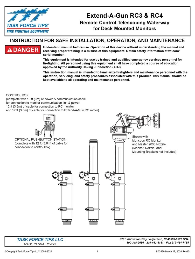
TFT Monsoon Series Instructions for installation, safe operation and maintenance

TFT
TFT Masterstream 4000 ER AUTOMATIC INSTRUCTIONS FOR SAFE OPERATION AND MAINTENANCE

TFT
TFT Extend-A-Gun XG18 Instructions for installation, safe operation and maintenance

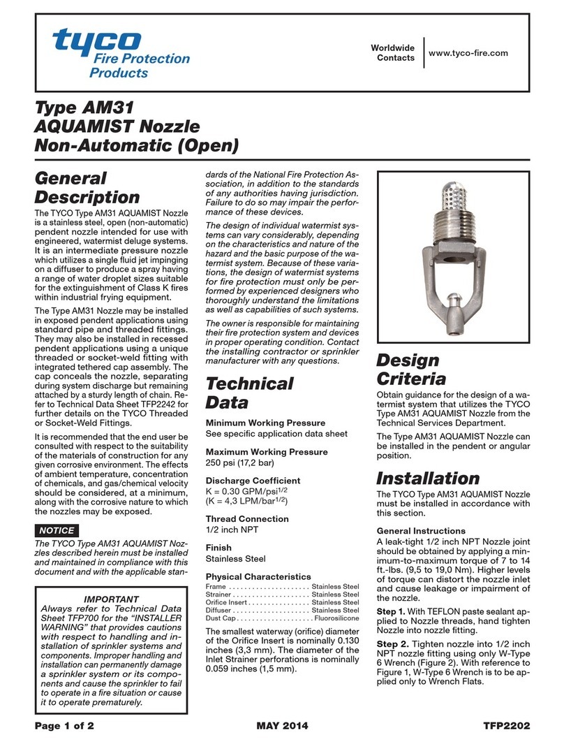
Tyco
Tyco TY-FRB Series quick start guide